IMS-1 (Indian Microsatellite-1)
EO
Mission complete
Imaging multi-spectral radiometers (vis/IR)
Land
Indian Microsatellite-1 (IMS-1), previously referred to as TWSat (Third World Satellite), was a microsatellite operated by ISRO (Indian Space Research Organisation) that launched in April 2008 and ended operations in July 2013. IMS-1 carried a multispectral and a hyperspectral sensor with the objective of providing medium-resolution imagery to developing countries for free.
Quick facts
Overview
| Mission type | EO |
| Agency | ISRO |
| Mission status | Mission complete |
| Launch date | 28 Apr 2008 |
| End of life date | 31 Jul 2013 |
| Measurement domain | Land |
| Measurement category | Multi-purpose imagery (land), Vegetation, Albedo and reflectance |
| Measurement detailed | Land surface imagery, Vegetation type, Earth surface albedo |
| Instruments | HySI (IMS-1), MxT |
| Instrument type | Imaging multi-spectral radiometers (vis/IR) |
| CEOS EO Handbook | See IMS-1 (Indian Microsatellite-1) summary |
Summary
Mission Capabilities
IMS-1 carried two payloads, a Multispectral Camera (MX) and a Hyperspectral Imager (HySI). To conserve resources onboard, only one instrument operated at a time.
MX observed over four spectral bands in VNIR (visible and near-infrared) and provided multi-purpose land-surface imagery and information on vegetation type, reflectance, and albedo. HySI was a prototype instrument that provided 64 fixed spectral bands in the VNIR region and was used on an experimental basis, with data applications including resource characterisation.
Performance Specification
MX operated in pushbroom scanning mode to image the Earth, with a spatial resolution of 36 m at nadir, and a swath of 151 km. HySI had a lower spatial resolution of 550 m at nadir, and a swath width of 128 km.
IMS-1 followed a sun-synchronous near-circular orbit with an altitude of 635 km, an inclination of 97.94°, and a period of 97.4 minutes.
Space and Hardware Components
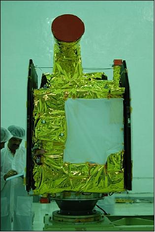
IMS-1 was a microsatellite version of the Indian Mini Satellite (IMS) developed by the ISRO. IMS-1 featured a three-axis stabilised bus with a modular design and a total mass of 83 kg.
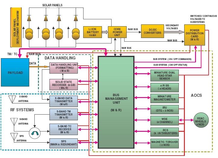
The IMS-1 EPS (Electric Power Subsystem) featured solar panels, a battery, power conditioning and distribution units, and the AOCS (Attitude and Orbit Control Subsystem) used sun sensors. The BMU (Bus Management Unit) provided functions including telecommand decoding, telemetry, data encoding, and sensor processing. S-band RF (radio frequency) communications were used for all TT&C (Telemetry, Tracking and Command) service functions and payload data transmission.
IMS-1 (Indian Microsatellite-1)
Overview
IMS-1, previously referred to as TWSat (Third World Satellite), is a low-cost microsatellite imaging mission of ISRO (Indian Space Research Organization). The overall objective is to provide medium-resolution imagery for developing countries for free. Around 50 data reception terminals will be installed by ISRO in selected Third World countries and also at some universities in India. 1) 2) 3) 4) 5)
Spacecraft
The project started in 2005 with a definition phase of the mission. The ISRO approach was to develop two versions of a standard small spacecraft bus (SSB) design with the objective to provide a low-cost and a quick-response time approach to space. 6)
• A microsatellite version (first use by the IMS-1 mission)
• A minisatellite version (first use by the SARAL mission)
The main advantage of these “smallsats” is the fact that they can be launched by a PSLV vehicle as a piggyback payload on any one of the larger primary payloads (like IRS satellites).
The modular design concept of the SSB is suited for series production making the bus a natural choice for constellation-flight applications. The design layout is such that the bus module and the payload module of each series may be integrated and tested separately (thus reducing the interdependency during the realization between both modules). Each SSB version is 3-axis stabilized. SSB is also designed to accommodate different types of payloads with minor modification from mission to mission.
Parameter | Microsatellite SSB | Minisatellite SSB |
SSB dimensions | 600 mm x 600 mm x 600 mm | 976 mm x 976 mm x 650 mm |
Total satellite mass | 83 kg | < 450 kg |
SSB mass | < 70 kg | 200 - 250 kg |
Total payload mass capacity | ≤ 30 kg | < 200 kg |
Power generation (average) | 220 W | 573 W |
Available payload power | 30 W | 200 W |
Pointing accuracy | ±0.1º | < ±0.1º |
Drift rate | 1 x 10⁻⁴ º/s | 1 x 10⁻⁴ º/s |
Data transmission rate | 8 Mbit/s in S-band | 20 Mbit/s in X-band |
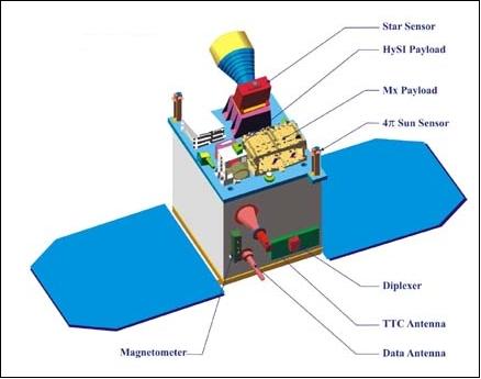
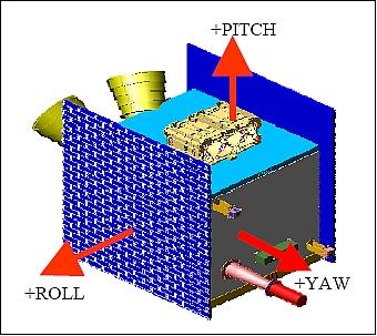
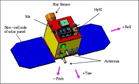
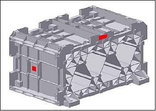
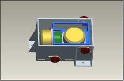
The SSB micro-bus uses aluminum honeycomb panels arranged in a cuboid structure with internal shear frames. This design is made to provide maximum area for mounting the packages while being sturdy. All the subsystem packages are mounted within the cuboid except sensors and antennas which are mounted outside. The structure includes a launch vehicle interface and solar panel interfaces. The payloads are mounted on the top deck, with optical axis towards the + yaw direction.
EPS (Electric Power Subsystem): The EPS consists of solar panels, battery, power conditioning and distribution units. There are two solar panels of size 0.81m x 0.72 m in the roll direction of the satellite. The panels are stowed during the launch and deployed after injection to the orbit. The satellite is nominally in sun-pointing mode with the solar panels facing the sun. For every payload operation, the satellite is maneuvered into an Earth-pointing mode and goes back to the sun-pointing mode after the imaging operation. Multi-junction solar cells are being used to provide higher efficiency of power conversion to generate about 230 W. A Li-ion battery is used with a capacity of 10.5 Ah, having a mass of about 3.5 kg. The EPS provides a single raw bus of 28 to 33 V. There are four DC/DC converters which provide the required secondary voltages for the payloads and bus subsystems.
AOCS (Attitude and Orbit Control Subsystem): The AOCS uses sun sensors with 4π FOV providing an accuracy of 0.1º in all axes -to meet the mission specification of band to band registration of 0.25 pixel for the multispectral camera. The sun sensors are being used for sun acquisition and safe mode detection and recovery. A MEMS-based magnetometer is being used in the spacecraft de-tumbling support mode and in the momentum dumping of the reaction wheels. A star sensor, providing an inertial quaternion output, is used as prime sensor during 3-axis stabilization and during the maneuver support modes. The accuracy of the star sensor is < 40 arcsec in all axes. In addition, there are two miniaturized gyros which are dynamically tuned. A GPS-based SPS (Satellite Positioning System) is used to provide the satellite position to an accuracy of < 30 m. Actuation is provided by magnetic torquers (momentum dumping), micro reaction wheels,and an RCS (Reaction Control Subsystem). The reaction wheels have an angular momentum capacity of 0.36 Nms and a torque of 0.015 Nm. The wheels are arranged in a tetrahedral configuration to provide enhanced torques about any axis. The RCS consists of a single tank (8 liter volume) containing a monopropellant fuel and a single 1N thruster. The thruster is primarily used for orbit corrections.
BMU (Bus Management Unit): The BMU represents the heart of the satellite providing the functions of telecommand decoding, house keeping telemetry, data encoding, sensor processing, on/off control of the subsystems and heaters, command distribution, spacecraft control during initial acquisition, normal mode, safe mode etc., using the actuators. This subsystem is realized in a single PCB (Printed Circuit Board).
Passive control methods (with elements like multi layer insulation blankets, optical surface reflectors, thermal paints and heaters wherever necessary.) are being used in the thermal control subsystem.
The propulsion subsystem consists of a single tank carrying 3.5 kg hydrazine. There is only single 1 N thruster, mounted centrally, it is mainly used for orbit correction.
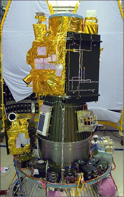
Launch
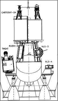
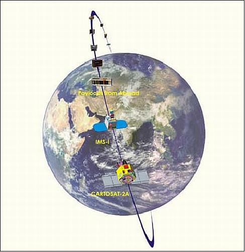
A launch of IMS-1 as a secondary payload on a PSLV vehicle (PSLV-C9) took place on April 28, 2008 from the SDSC-SHAR launch site (Sriharikota, India) of ISRO. - The primary payload on this flight was CartoSat-2A (launch mass of 690 kg), an Indian military high-resolution panchromatic imaging satellite (based on CartoSat-2 of ISRO). 7) 8)
Further secondary smallsat payloads on this flight were:
• CanX-2 a triple CubeSat of the University of Toronto (UTIAS/SFL, 3.5 kg), Toronto, Canada. Objective: Testing of a nano cold gas propulsion system, innovative attitude sensors and a commercial GPS receiver.
• CUTE-1.7+APD-2 (3.5 kg) CubeSat of the Tokyo Institute of Technology (TITech). Objective: Demonstration of a PDA (Personal Digital Assistant) based bus system and APD (Avalanche Photodiode).
• AAUSat-2 a CubeSat of Aalborg University, Denmark (3 kg). Objective: Detection of gamma-ray bursts; flight testing of nano actuators and sensors for spacecraft 3-axis stabilization.
• Delfi-C3 (6.5 kg) of the Technical University of Delft, The Netherlands. Objective: Flight testing of film solar cells, wireless sun sensor and advanced transceiver.
• COMPASS-1 (1.0 kg) of the University of Applied Science, Aachen, Germany. Objective: Flight testing of a miniaturized spacecraft bus.
• SEEDS-2 (3.0 kg) of Nihon University, Japan. Objective: Demonstration of receiving spacecraft parameter data by CW (Continuous Wave) signal, FM packet downlink and sound data by a digi-talker.
• NTS (Nanosatellite Tracking of COM DEV / UTIAS/SFL, Toronto, Canada. Objective: Perform a survey of the maritime VHF band at 162 MHz. The payload is a VHF receiver.
• Rubin-8-AIS an experimental space technology mission of OHB-System, Bremen, Germany. Objective: Testing of an improved spaceborne receiver and data upload system for AIS (Automatic Identification System) support.
Note: The cluster of the first six nanosatellites, (CanX-2, CUTE-1.7+APD-2, AAUSat-2, Delfi-C3, COMPASS-1 and SEEDS-2), is also referred to as NLS-4 (Nanosatellite Launch System-4). The launch of the 8 nanosatellite payloads was executed under a commercial contract between the University of Toronto, COSMOS International (a company of the OHB Fuchs Gruppe, Bremen, Germany), and the Antrix Corporation of Bangalore, India (the latter is the commercial arm of ISRO).
The XPOD (Experimental Push Out Deployer) system of UTIAS/SFL was used to deploy the following secondary payloads: CanX-2, SEEDS-2, Delfi-C3, COMPASS-1, AAUSat-2, and NTS. 9)

Orbit: Sun-synchronous near-circular orbit, altitude = 635 km, inclination = 97.94º, the period is 97.4 minutes, the local time on the descending node (LTDN) is at 9:30 hours.
RF communications of IMS-1: The S-band (2.280 GHz) is used for all TT&C service functions as well as for payload data transmission. The radiated power is 5 W. The downlink payload data rate is 8 Mbit/s. The modulation is PCM/BPSK. The TT&C data is downlinked at a rate of 4 kbit/s.
Users will be provided with ground terminals capable of tracking the satellite in program mode.
Operating frequency | 2.2 - 2.3 GHz |
Antenna | 3.7 m parabolic reflector |
Feed | S-band receive feed with RHCP (Right Hand Circular Polarization) |
Tracking modes | Program or manual |
Gain | 35 dBi |
G/T (Gain / Temperature) | 12 dB/K |
Receiver I/F | 70 MHz |
Demodulator I/P range | -100 to -50 dBm |
Mission Status
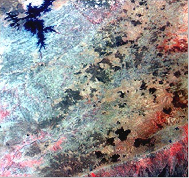
• The IMS-1 spacecraft and its payload are operating nominally in 2012. Both payloads (Mx and HySI) are being operated regularly returning excellent quality imagery (Ref. 10).
• The IMS-1 spacecraft and its payload are operating nominally in 2011 providing excellent quality imagery from both sensors (Ref. 10).
• The spacecraft and its payload are operating nominally in 2010. 10) 11)
• The spacecraft and its payload are operating nominally as of the fall of 2008.
• The first Mx payload operation was performed on day 2, and HySI payload was performed on day 3 from launch. The payload operations were scheduled for the first one-week such that all possible combinations of operations (i.e.) Mx near real-time and recording, HySI near real-time and recording modes were individually exercised. All the new software, hardware logic and the payload modes were exercised and the operations were declared normal. 12)
The IMS-1 routine operations began one month after launch. During the instruments commissioning phase, calibration exercises were performed using star sensor and gyro data. The image data was collected on test beds with good ground control points. The biases and misalignments between star sensor and payload axis were estimated and the necessary corrections were uploaded to the spacecraft (Ref. 12).
Sensor Complement
IMS-1 (TWSat) carries two payloads: the Mx (Multispectral Camera) and the HySI (Hyperspectral Imager). However, since the data of both imagers is rather high, only one of them will be powered on and data transmitted at any given time. 13) 14)
Mx (Multispectral Camera)
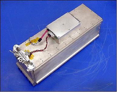
The instrument of modular design provides four spectral bands in VNIR, where each band employs an individual lens, a separate CCD detector, and separate front-end electronics. The camera operates in a pushbroom scanning mode to image the Earth. The spatial resolution at nadir is 36 m on a swath of 151 km. The 12 bit video output is coded to 10 bit with multi-linear gain. Mx has a mass of 5.5 kg and a power consumption of 18 W.
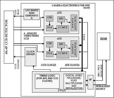
All the front end electronics and the video processors are accommodated on the electro optical module (EOM) itself. Each band has one detector which gives out data in 4 ports with 10 bits per pixel. The source data (32 Mbit/s) is sent to the baseband data handling system of the microsatellite bus, compressed and stored in SSR (Solid State Recorder) of 16 Gbit capacity. The recorded data is transmitted to the ground in S-band at 8 Mbit/s.
Spectral bands | VIS1: 0.45-0.52 µm |
Spatial resolution at nadir, swath width | 37 m, 151 km |
FOV (Field of View) | ± 7º |
Detector | 4 k linear CCD array with a pixel size of 7 µm x 7 µm |
Data quantization | 10 bit |
Instrument mass, power | 5.8 kg, 10 W |
Source data rate | 32 Mbit/s |
Data compression algorithm | JPEG2000 (compression ratio of 3.4:1) |
Data transmission rate | 8 Mbit/s in S-band (after data compression and onboard storage) |
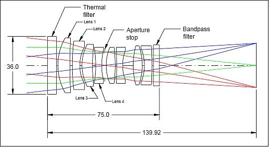
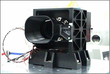
The collecting optics is shown in Figure 11 for a spectral band is an eight-element lens assembly with a thermal filter at the front and a bandpass filter (to select the respective spectral range) at the rear. An f/5 optics system is used at a spatial frequency of 70 l/mm over a field of view (FOV) of ± 7º. All 4 lens assemblies use an identical design and assembly/alignment of the lens elements. The mass of each lens assembly is only 266 g.
There are also separate miniaturized camera electronics for each band, including COTS components, realized in a single PCB (Printed Circuit Board).
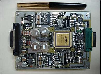
The Mx camera represents the first miniaturized payload made by India for mini/micro class satellites. It uses indigenously developed and qualified lenses, linear CCDs and other electronic components.
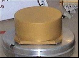
HySI (Hyperspectral Imager)
The prototype instrument is providing a total of 64 spectral bands in the VNIR region. Spectral separation is realized using the wedge filter technique. Detection is provided with a CMOS/APS (Active Pixel Sensor) area device. - The HySI data may be used for resource characterization and detailed studies. The HySI is being used on an experimental basis to obtain experience of such a payload and also of handling the hyperspectral data and generating the application models.
The sun's reflected light from Earth’s surface is being collected through a telecentric refractive optics system and is being focused onto an APS area detector. The area detector images 260 km in along-track and 128 km of cross-track area on ground in an integration time 78.45 ms. The APS area detector has 256 x 512 pixels of 50 µm pixel size; 256 elements are in the cross-track direction and 512 elements are in the along-track direction. 15)
Spectral separation is realized using the wedge filter technique making use of APS (Active Pixel sensor) area device for detection.
Instrument type | Pushbroom imager |
Spectral range | 0.4 - 0.95 µm (VNIR) |
No of spectral bands, spectral range | 64 (fixed, contiguous bands), 0.45-0.95 µm |
Spectral bandwidth | < 15 nm |
Sampling interval | 8 nm |
Spatial resolution | 550 m at nadir |
Swath width | 128 km |
Detector | An APS (Active Pixel Array) is used with 512 rows and 250 columns |
Data quantization | 10 bit |
Instrument mass, power, size | 3.4 kg, 4 W, 15 cm x 20 cm x 17 cm |
Source data rate | 32 Mbit/s |
Data compression algorithm | JPEG2000 (compression ratio of 3.4:1) |
Data transmission rate | 8 Mbit/s in S-band (after data compression and onboard storage) |
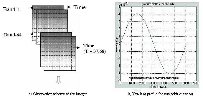
The observation scheme is shown in Figure 16a. To cover the same area by Band-1 as seen by Band-64, it takes around 37.68 seconds. During this observation period, the area as seen by Band-64 moves eastwards by 17.4 km because of Earth rotation. This results in a pixel offset of around 34 pixels out of 256 pixels. The specification requires to limit this rotation effect on the footprint to about 0.1 pixels. It turns out that the Earth rotation effect is more pronounced in the equatorial region and less in the polar regions. The yaw bias profile for one orbit duration is shown in Figure 16b.
Mission operations: While Mx serves the basic requirement of the imaging mission, the HySI is incorporated on an experimental basis. It is planned to operate the Mx instrument for most of the orbits based on the user demands, while the HySI is operated over Indian ground stations for evaluation purposes. Either of the payloads will be operated at a time in order to conserve the available resources on board the microsatellite.
The data from the two payloads is being downlinked separately. The Mx data is compressed at a ratio of 3.4:1, formatted, RS (Reed Solomon) encoded and stored on SSR (Solid Sate Recorder). The downlink is in near real-time via the S-band transmitter. The SSR has the storage capacity of 16 Gbit providing a maximum storage volume of 20 minutes data in segmented form.
Introduction of New Technologies
The new technologies introduced into the IMS-1 development are:
• Miniature magnetometers with MEMS-based mag in one channel (used for one axis). The magnetometers are used during the de-tumbling of the spacecraft and for momentum dumping of wheels.
• Miniature sun sensors with a FOV (Field of View) of 4π
• Miniature micro reaction wheels and a gyro cluster
• Miniature digital S-band receiver and transmitter
• Miniature SPS (Satellite Positioning System)
• Miniature multispectral camera in 4 bands
• Innovative (mission specific) thermal subsystem
• Innovative integration and ground checkout procedures.
References
1) D. R. M. Samudraiah, D. V. A. Raghava Murthy, “Small Satellites Planned by ISRO for Earth Observation,” 58th IAC (International Astronautical Congress), International Space Expo, Hyderabad, India, Sept. 24-28, 2007, IAC-07-B4.4.08
2) S. A. Kuriakose, D. Subrahmanyam, S. S. Sarkar, V. D. Patel, N. Mathur , “Design and development of the multispectral payload for TWSat mission,” Proceedings of SPIE, 'Multispectral, Hyperspectral, and Ultraspectral Remote Sensing Technology, Techniques, and Applications,' William L. Smith, Sr., Allen M. Larar, Tadao Aoki, Ram Rattan, Editors, 640516, Vol. 6405, published online Dec. 22, 2006, SPIE conference at Panaji, Goa, India, Nov. 13-17, 2006
3) K. Thyagarajan, D. V. A. Raghava Murthy, “Micro and Mini Satellites of ISRO - Technology and Applications,” 58th IAC (International Astronautical Congress), International Space Expo, Hyderabad, India, Sept. 24-28, 2007, IAC-07-B4.1.09
4) K. Thyagarajan, D. V. A. Raghava Murthy, “Remote Sensing Mission Using Micro and Minisatellites,” Proceedings of the International Workshop on Earth Observation Small Satellites for Remote Sensing Applications (EOSS 2007), Kuala Lumpur, Malaysia, Nov. 20-23, 2007
5) Karl Staenz, “Terrestrial Imaging Spectroscopy - Some Future Perspectives,” 6th EARSeL Workshop on Imaging Spectroscopy, Tel-Aviv, Israel, March 16-19, 2009, URL: http://www.earsel.org/workshops/IS_Tel-Aviv_2009/PDF/earsel-PROCEEDINGS/3079%20Staenz.pdf
6) D. V. A. Raghava Murthy, “Small satellite busses catering for different missions,” Proceedings of the 60th IAC (International Astronautical Congress), Daejeon, Korea, Oct. 12-16, 2009, IAC-09.B4.4.8
7) “PSLV-C9 Mission,” ISRO Newsletter, April-Sept. 2008, URL: http://www.isro.org/newsletters/scripts/newslettersin.aspx?page4AS88
8) Rashid Faridi, “ISRO Launch Perfect:PSLV-C9 launched successfully with 10 satellites,” April 28, 2008, URL: http://rashidfaridi.wordpress.com/2008/04/28/isro-launch-perfectpslv-c9-launched-successfully-with-10-satellites/
9) Freddy M. Pranajaya, “SFL Nanosatellite Missions and Launches in 2007-2009,” April 19, 2007, URL: http://mstl.atl.calpoly.edu/~workshop/archive/2007/Spring/01b-Pranajaya-SFL.pdf
10) Information provided by A. S. Kiran Kumar of ISRO SAC, Ahmedabad, India
11) Paul Debashish, M. Pitchamani, S. K. Shivakumar, “Emergency Imaging Feasibility,” Proceedings of the SpaceOps 2010 Conference, Huntsville, ALA, USA, April 25-30, 2010, paper: AIAA 2010-2032
12) Devayani Perur, M. Srikanth, “IMS-1 mission planning, analysis and operations – outline of key components,” Proceedings of the Symposium on Small Satellite Systems and Services (4S), Funchal, Madeira, Portugal, May 31-June 4, 2010
13) R. Srinivasan, J. R. Subramanian, M. Pitchaimani, S. K. Shivakumar, “TWSAT – Mission Operations Plan,” Proceedings of the 59th IAC (International Astronautical Congress), Glasgow, Scotland, UK, Sept. 29 to Oct. 3, 2008, IAC-08.B4.3.9
14) D. Subrahmanyam, A. S. Kiran Kumar, D. R. M. Samudraiah, Saji . A. Kuriakose, S. S. Sarkar, R. M. Parmar, Vishnu Patel, Neeraj Mathur, H. B. Pandya, M. P. Detroja, Satish Rao, Harish Seth, “Miniature Multispectral Camera for IMS Mission,” Proceedings of the 59th IAC (International Astronautical Congress), Glasgow, Scotland, UK, Sept. 29 to Oct. 3, 2008, IAC-08.B4.6.A12
15) A. Kumar, .A. Saha, .V. K. Dadhwal, “Some Issues Related with Sub-pixel Classification using HYSI Data from IMS-1 Satellite,” Journal of the Indian Society of Remote Sensing, Vol. 38, No 2, June 2010, pp. 203-210, DOI: 10.1007/s12524-010-0027-5
16) A. S. Kiran Kumar, “Hyperspectral imaging, ISRO plans,” Second HyspIRI NASA Decadal Survey Mission Science Workshop, Pasadena, CA, USA, Aug. 11-13, 2009, URL: http://hyspiri.jpl.nasa.gov/downloads/2009_Workshop/day3/day3_6._isro_plans_for_hysi.pdf
The information compiled and edited in this article was provided by Herbert J. Kramer from his documentation of: ”Observation of the Earth and Its Environment: Survey of Missions and Sensors” (Springer Verlag) as well as many other sources after the publication of the 4th edition in 2002. - Comments and corrections to this article are always welcome for further updates (eoportal@symbios.space).