IRS-P3 (Indian Remote-Sensing Satellite-P3)
EO
Atmosphere
Ocean
Cloud type, amount and cloud top temperature
Quick facts
Overview
| Mission type | EO |
| Agency | ISRO |
| Mission status | Mission complete |
| Launch date | 21 Mar 1996 |
| End of life date | 31 Dec 2003 |
| Measurement domain | Atmosphere, Ocean, Land, Snow & Ice |
| Measurement category | Cloud type, amount and cloud top temperature, Ocean colour/biology, Aerosols, Multi-purpose imagery (land), Vegetation, Albedo and reflectance, Landscape topography, Snow cover, edge and depth |
| Measurement detailed | Ocean chlorophyll concentration, Aerosol optical depth (column/profile), Cloud type, Aerosol Extinction / Backscatter (column/profile), Land surface imagery, Aerosol effective radius (column/profile), Vegetation type, Earth surface albedo, Land surface topography, Snow cover |
| Instruments | MOS, WiFS, X-ray astronomy payload |
| Instrument type | Imaging multi-spectral radiometers (vis/IR), Other |
| CEOS EO Handbook | See IRS-P3 (Indian Remote-Sensing Satellite-P3) summary |
IRS-P3 (Indian Remote-Sensing Satellite-P3)
IRS-P3 is an ISRO (Indian Space Research Organization) experimental EO (Earth Observation) mission, a follow-up mission to IRS-P2, considered to be preoperational and serving in parallel for technology evaluation and scientific methodology studies. A portion of the payload is provided by DLR (German Aerospace Center) in the framework of a cooperative agreement between ISRO and DLR. In addition, DLR provides data reception support (Neustrelitz) and launch phase support. The objectives of the mission are:
• Technological test of the PSLV launch vehicle
• Scientific remote sensing applications and algorithm development based on joint interpretation of MOS and WiFS data
• Preoperational test of data processing and algorithm concepts
• Radioastronomy experiments using the X-ray payload
Spacecraft
The IRS-P3 spacecraft structure is of IRS-P2 heritage. The bus design consists of four vertical panels and two horizontal decks supported on a central load-bearing cylinder of 930 mm diameter and 1188 mm height. The payload is accommodated on the outer side of the upper deck, it is oriented in flight direction. The onboard power generation is achieved by a pair of deployable, sun-tracking, uncanted solar panels (9.636 m2), which generates a power of 873 W. Two NiCd batteries (21 Ah/24 Ah) cater to the eclipse and peak load demands.
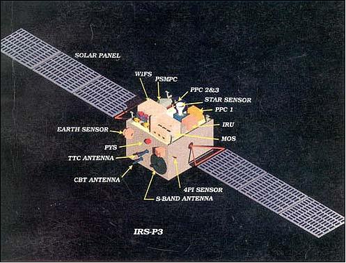
The S/C is three-axis stabilized. The AOCS employs Earth sensors, sun sensors and dynamically tuned gyros as attitude sensors; actuation is provided by reaction wheels, magnetic torquers and an RCS (Reaction Control System). An Earth pointing accuracy of better than 0.20º in all axes and better than 0.05º in all axes for stellar pointing (X-ray observation mode) is provided. In addition to these attitude sensors, AOCS also employs a star sensor in control loop in order to maintain the attitude during stellar pointing mode. The star sensor is an area array CCD imager of 288 x 384 pixels (FOV of 6º x 8º). It works as a star tracker with respect to a set of optical stars, identified a priori in conjunction with the X-ray package. The star sensor is mounted on positive roll axis and co-aligned with the X-ray payload's optical axis. When the spacecraft is inertially oriented and locked to a specified X-ray source, the star sensor works in a static mode. Therefore, the star sensor always locks to a specific scene about the roll axis. 1) 2)
Total S/C mass = 922 kg, a hydrazine propulsion system (84 kg of fuel sufficient for three years) with 16 thrusters is used for orbit maintenance.

Launch
A launch of IRS-P3 took place on March 21, 1996 on an ISRO PSLV-D3 (Polar Satellite Launch Vehicle-Developmental flight 3) launcher from SHAR (Sriharikota Range), India, a launch site on India's east coast, representing the second successful test launch of PSLV. 3)
Orbit: Sun-synchronous circular orbit, altitude = 817 km, inclination = 98.7º, repeat cycle = 24 days, period = 101.35 min, local equatorial crossing at 10:30 hours on a descending node.
RF communications: The TT&C-system is operating in S-band with PCM/FSK/FM/PM modulation. The telemetry system uses PCM/PSK modulation in S-band (2203 MHz). The payload data is transmitted in S-band (2280 MHz) with BPSK modulation at a data rate of 5.2 Mbit/s. The spacecraft features in addition a C-band transponder (CBT) which acts as a dynamic target for calibrating PCMC (Precision Coherent Monopulse C-band) radars, supporting the Indian launches.
MOS instrument science data are being received at the following ground stations:: Hyderabad (ISRO, India), Neustrelitz (DLR, Germany), Maspalomas (ESA, Spain - since 1998), Wallops Island (NASA, USA - since April 1999).
Mission Status
Mission operations of the spacecraft at ISRO were terminated in the fall of 2004. The operational life of the spacecraft represented more than twice the design life of 3 years.
• In the fall of 2003, IRS-P3 encountered increasing energy problems (insufficient electrical power) and also orbit maintenance problems (the equatorial crossing time moved into the early morning hours between 8 and 9 AM).
• The contracts for MOS data reception (DLR, ESA, and NASA) were terminated for the end of 2003, this meant also the near end for MOS instrument operations.
• There were only sporadic MOS data receptions in 2004 (for instance, ESA had its last MOS data reception in March of 2004). DLR declared the final end of MOS operations as of May 31, 2004. ISRO continued operations of the IRS-P3 spacecraft until the fall of 2004. 4)
Sensor Complement
WiFS (Wide Field Sensor)
WiFS is an ISRO pushbroom imager of IRS-1C and IRS-1D heritage. WiFS is an extended version of 3 channels on IRS-P3: 0.62 - 0.68 µm, 0.77 - 0.86 µm, with an additional channel at 1.55-1.75 µm (SWIR). Each band has two detectors centered at a FOV of ±13.6º to achieve a swath of 770 km (repeat cycle of 5 days). The optics system consists of eight lenses with spectral bandpass and neutral density filters for each spectral band. The dynamic range in each gain is 7 bits. The absolute radiometric accuracy is better than 10% with relative in-band accuracy of 2%. The data rate for the VNIR data (2 channels) is 2.6 Mbit/s, for the SWIR data it is 1.73 Mbit/s. WiFS has a mass of 25 kg and uses 50 W. The objectives of WiFS observations are to monitor the vegetation index on land and to observe the ocean surface. 5) 6)
Spectral bands (µm) | 0.62 - 0.68, 0.77 - 0.86, 1.55 - 1.75 (SWIR) |
Spatial resolution | 188 m |
Swath width | 770 km (FOV of ±13.6º), 4096 pixels |
Repetition cycle | 5 days |
SNR at saturation radiance | >128 |
Data quantization | 7 bit (radiometric resolution of 128 grey levels) |
Integration time | 28.42 ms |
Data rate | 2.06 Mbit/s |
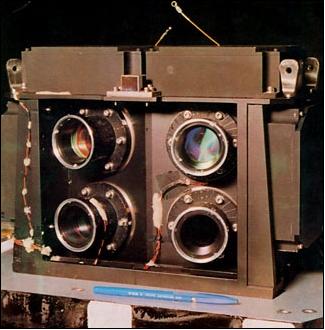
MOS (Multispectral Optoelectronic Scanner)
MOS is an experimental imaging pushbroom spectrometer for VNIR/SWIR range observations. MOS is provided by DLR (German Aerospace Center), Berlin. The objective is to monitor the Earth's surface (surface-atmosphere interaction, ocean color, phytoplankton, regional and global distributions of man-made aerosols and their links to gaseous admixtures, spectral and spatial cloudiness characteristics, etc.) in the VNIR/SWIR region of 0.4 - 1.6 µm. 7) 8) 9) 10)
The sensor apparatus consists of three complementary instruments. MOS operation requires at least one calibration per month (with respect to the sun).
• MOS-A is an atmospheric spectrometer with four narrow channels in the O2A-absorption band at about 760 nm for the measurement of atmospheric turbidity. The data from MOS-A are used for correction of the atmospheric influence (scattering) on the multispectral data of MOS-B. In addition the O2A-method permits the measurement of aerosol content and profile.
• MOS-B is a 13-channel spectrometer in the spectral range of 408 to 1010 nm. The center wavelengths of the channels are chosen with the objective for the quantitative retrieval of ocean and coastal zone parameters. They also provide a capability for vegetation signature determination (red edge) and estimation of H2O (water vapor) content in the atmosphere from the NIR-measurements.
• MOS-C is a line camera at 1.6 µm with a bandwidth of "50 nm. The SWIR channel data is used for improved surface term and roughness estimation. In addition the data of the SWIR channel may be used for the following applications: cloud/snow/ice discrimination, cloud type discrimination, estimation of sea surface roughness, and for the improvement of atmospheric correction algorithms.
Parameter | MOS-A | MOS-B | MOS-C |
Spectral range (nm) | 755 - 768 nm | 408 - 1010 | SWIR |
No. of channels | 4 | 13 | 1 |
Wavelengths (nm) | 756.7; 760.6; 763.5; 766.4 (O2A-band) | 408; 443; 485; 520; 570; 615; 685; 750; 870; 1010; 815; 945 (H2O-vapor) | 1600 |
Spectral resolution | 1.4 nm (FWHM) | 10 nm (FWHM) | 100 nm (FWHM) |
FOV along-track | 0.344º | 0.094º | 0.14º |
Swath width | 195 km | 200 km | 192 km |
No. of pixels per row | 140 | 384 | 299 |
Spatial resolution (ground pixel size) | 1.57 km x 1.4 km | 0.52 km x 0.52 km | 0.52 km x 0.64 km |
Measuring range Lmin-Lmax | 0.1 - 40 | 0.2 - 65 | 0.5 - 18 |
Data quantization | 16 bit | ||
Data rate | 1.3 Mbit/s | ||
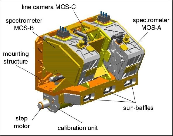
MOS calibration: In-orbit calibration measurements are performed using internal reference lamps (prior to each data take). In addition sun calibration measurements are performed once a month. This is achieved with a diffuser in front of the entrance optics of the sensor. The following calibration functions are performed:
• DSNU (Dark Signal Non-Uniformity) and PRNU (Photo Response Non-Uniformity)
• Absolute sensitivity calibration
• Linearity control
• Spectral alignment control
MOS in-orbit intercalibrations with sensors from other missions are attempted when orbital opportunities arise for a common target area or test sites. Examples are: MOS on IRS/P3 with MOS on Priroda, or with SeaWiFS on Seastar, or with OCTS on ADEOS.
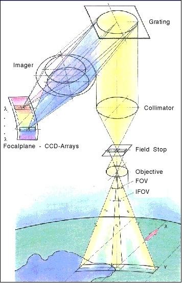
Principle of the imaging pushbroom spectrometer operation: A strip (swath) of the Earth's surface is imaged through the entrance optics on the field stop. The collimator optics realizes parallel light rays falling onto the grating. The grating disperses the different “colors” that are focussed by the imager into the focal plane. Corresponding to the desired wavelength, CCD line arrays are mounted into the focal plane.

IXAE (Indian X-ray Astronomy Experiment)
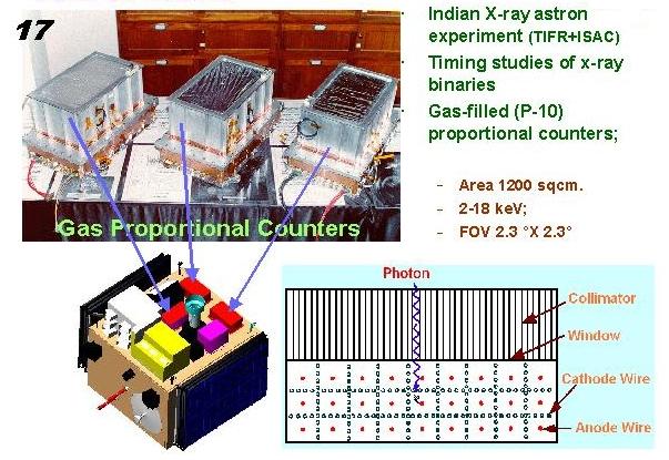
IXAE is an ISRO/ISAC and TIFR (Tata Institute of Fundamental Research, Mumbai, India) cooperative experimental astronomy instrument package with the objective to study periodic and aperiodic intensity and spectral variations in X-ray sources. Source observation is achieved by `pointed mode observations,' employing an array of three co-aligned collimated PPC (Pointed Proportional Counter). The system operates in mutual anti-coincidence fashion for significant reduction of background noise (cosmic rays and Compton interaction of gamma rays). 11) 12) 13)
Another objective is the study of light curves and the spectral evolution of transient and flaring X-ray sources as well as long-term intensity monitoring of known binary X-ray stars and other bright X-ray sources. This is achieved by means of XSM (X-ray Sky Monitor), based on the principle of a pin hole placed above a position sensitive to PPC in anti-coincidence mode.
PPC | XSM | ||
Energy range | 2 - 20 keV | Energy range | 2 - 8 keV |
FOV | 2º x 2º | FOV | 90º x 90º |
No of PPC | 3 | Pin hole size | 1 cm2 |
No of layers per PPC | 3 | Distance to detector | 16 cm |
No. of anode cells/layer | 18 | Detector | 32 proportional counters |
Size of cell | 1.1 cm x 1.1 cm | Detector cell size | 1 cm x 1 cm x 32 cm |
Entrance window | 25µm , 500 Å, Al coated | Window | 25 µm Mylar, Al coated |
Filling gas | Ar+CH4, at 800 torr | Filling gas | Ar+CH4 |
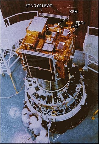
The principle objective of the IXAE is to carry out timing studies of X-ray pulsars, X-ray binaries, and other rapidly varying X-ray sources. The XSM detects transient X-ray sources and monitors the light intensity of bright X-ray binaries. Each of the detectors (PPC, XSM) are controlled by independent microprocessor based processing electronics. A common electronics subsystem acts as an interface with the satellite bus. An oven controlled oscillator (accuracy one part in 109) provides high timing accuracy.
The PPC is a multi-cell multi-layer proportional counter array with active anticoincidence on three sides. The total geometric area is about 400 cm2, the filling gas is 90% Argon + 10% Methane. A 25 µm aluminized mylar acts as the entrance window. The field of view is restricted to 2º x 2º using a passive collimator. The detector has a command controlled high voltage unit. The processing electronics for the PPC has an onboard memory of 512 kByte, the spectra (64 channels spanning 2 to 30 keV) and light-curves are stored onboard with the command selectable integration times.
The XSM is a planar position sensitive proportional counter with a pin-hole of 1 cm2 positioned 16 cm above the detection plane. The FOV is 90º x 90º. The detection plane consists of 32 proportional counter cells with a resistive wire (NiCr) as the anode. Position resolution along the wires is achieved by charge division and perpendicular to the wires it is achieved by cell placement (1 cm). The energy range of the detector is 2 to 8 keV.
References
1) J. D. Rao, T. V. S. R. K. Prasad, P. Soma, S. K. Shivakumar, “Innovative Mission Operations of IRS-P3,” http://www.aiaa.org/Spaceops2002Archive/papers/SpaceOps02-P-T3-59.pdf
2) K. Thyagarajan, A. Neumann, G. Zimmermann, “The IRS-P3 Remote Sensing Mission,” Small Satellites for Earth Observation, International Symposium of IAA, Berlin, Nov. 4-8, 1996
3) http://www.isro.org/satellites/irs-p3.aspx
4) Information provided by Andreas Neumann of DLR, Berlin, Germany
5) K. Thyagarajan, A. Neumann, G. Zimmermann, “The IRS-P3 remote sensing mission,” Acta Astronautica, Vol. 39, No 9, Nov. 1996, pp. 711-716
6) http://www.csre.iitb.ac.in/isro/irs-p3.html
7) G. Zimmermann, A. Neumann, “The Imaging Spectrometer Experiment MOS on IPR-P3 - Three Years of Experience,” Journal of Spacecraft Technology, Vol. 10, No 1, Jan. 2000, pp. 1-9
8) H. H. Schwarzer, K.-H. Suemnich, A. Neumann, T. Walzel, G. Zimmermann, “Three years of successful in-orbit calibration of the modular optoelectronic scanner (MOS) on the Indian IRS-P3 mission,” Proceedings of SPIE, Vol. 3750, 'Earth Observing Systems IV,' William L. Barnes, Editor, September 1999, pp. 466-469
9) http://www.ioccg.org/reports/mos/mos.html
10) M. Hetscher; H. Krawczyk; A. Neumann; G. Zimmermann, “ Four years of ocean colour remote sensing with MOS-IRS,” International Journal of Remote Sensing, Vol. 25, No 7-8, April 10-20, 2004 , pp. 1415-1421
11) A. R. Rao, “The Indian multi-wavelength astronomy satellite,” Bulletin of the Astronomical Society of India, Vol. 27, 1999, p.289, 1999BASI...27..289R
12) Sachindranatha Naik, P. C. Agrawal, “Temporal Studies of X-ray Binaries with IXAE,” Tata Institute of Fundamental Research, Mumbai, India, 2003, URL: http://www.tifr.res.in/~sachi/snaik_thesis.pdf
13) P. C. Agrawal, K. Mukerjee, S. Naik, B. Paul, A. R. Rao, J. S. Yadav, K. Kasturirangan, S. Seetha, K. Y. Singh, “Studies of binary sources with the Indian X-ray Astronomy Experiment,” Advances in Space Research, Volume 25, Issues 3-4, 2000, pp: 357-362
The information compiled and edited in this article was provided by Herbert J. Kramer from his documentation of: ”Observation of the Earth and Its Environment: Survey of Missions and Sensors” (Springer Verlag) as well as many other sources after the publication of the 4th edition in 2002. - Comments and corrections to this article are always welcome for further updates (eoportal@symbios.space).