IRS-P4 (Indian Remote Sensing Satellite -P4) / OceanSat-1
EO
Ocean colour instruments
Atmosphere
Ocean
Quick facts
Overview
| Mission type | EO |
| Agency | ISRO |
| Mission status | Mission complete |
| Launch date | 26 May 1999 |
| End of life date | 31 Dec 2010 |
| Measurement domain | Atmosphere, Ocean, Land, Snow & Ice |
| Measurement category | Liquid water and precipitation rate, Ocean colour/biology, Aerosols, Multi-purpose imagery (ocean), Multi-purpose imagery (land), Vegetation, Albedo and reflectance, Surface temperature (ocean), Landscape topography, Ocean topography/currents, Sea ice cover, edge and thickness, Snow cover, edge and depth, Ocean surface winds, Atmospheric Winds |
| Measurement detailed | Ocean imagery and water leaving spectral radiance, Ocean chlorophyll concentration, Precipitation intensity at the surface (liquid or solid), Aerosol optical depth (column/profile), Aerosol Extinction / Backscatter (column/profile), Land surface imagery, Aerosol effective radius (column/profile), Vegetation type, Earth surface albedo, Sea surface temperature, Land surface topography, Wind vector over sea surface (horizontal), Ocean suspended sediment concentration, Sea-ice cover, Snow cover, Wind profile (horizontal), Sea-ice thickness, Ocean dynamic topography |
| Instruments | WiFS, OCM (Oceansat-2), MSMR |
| Instrument type | Ocean colour instruments, Imaging multi-spectral radiometers (vis/IR), Imaging multi-spectral radiometers (passive microwave) |
| CEOS EO Handbook | See IRS-P4 (Indian Remote Sensing Satellite -P4) / OceanSat-1 summary |
OceanSat-1 - Formerly IRS-P4 (Indian Remote Sensing Satellite -P4)
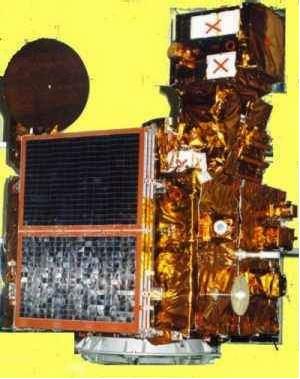
OceanSat-1 is a spacecraft developed at ISRO (Indian Space Research Organization) within the IRS series referred to as IRS-P4. The objectives of the IRS-P4 mission are directed at ocean- and atmosphere-related applications; hence, prior to launch, ISRO renamed the spacecraft mission to OceanSat-1.
Spacecraft
The S/C structure (aluminum/aluminum honeycomb structure with CFRP elements) is of IRS-1C/1D, and IRS-P3 heritage. The platform is three-axis stabilized, the pointing accuracies are ±0.15º in pitch/roll and ±0.20º in yaw; the drift rate is < 0.0003º/s. Attitude is measured by Earth sensors, sun sensors, a magnetometer and gyros. Actuators: reaction wheels, magnetic torquers and hydrazine thrusters. An onboard storage capability of 320 Mbit is provided. 1) 2) 3) 4) 5)
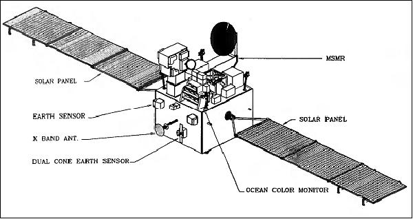
Spacecraft mass = 1050 kg; power = 800 W at EOL; two NiCd batteries provide 2 x 21 Ah. The spacecraft size is: 2.8 m x 1.98 m x 2.57 m. The mission design life is 5 years.
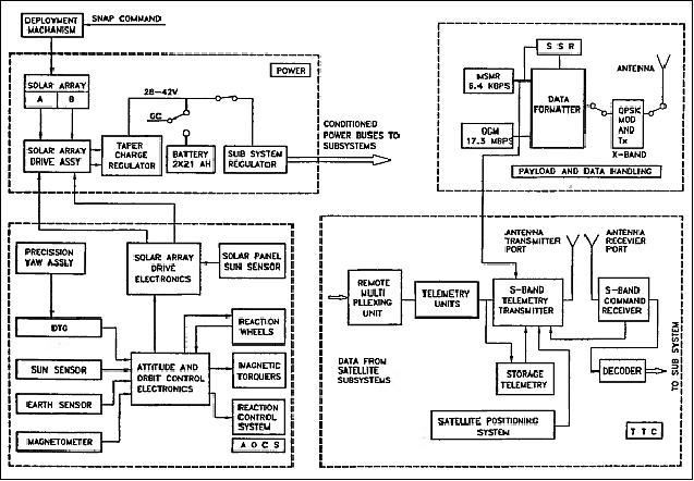
RF communications: The TT&C functions are carried out by the ISRO/ISTRAC control center with ground stations at Bangalore, Lucknow and Hyderabad (payload data and TT&C) in India and from its station in Mauritius. External ground stations at Bearslake (OKB/MEI), Biak (Indonesia) and the DLR station in Weilheim (Germany). The payload data reception stations are operated by NRSA (National Remote Sensing Agency) at Hyderabad and Shadnagar. The real-time data from OCM and MSMR playback data are downlinked in X-band (8.350 GHz) at 20.8 Mbit/s, while the real-time MSMR data as well as housekeeping data are transmitted in S-band.

Mechanical system Thermal control |
|
Power system |
|
TT&C system (S-band) |
|
AOCS |
|
Data handling system |
|
S/C positioning system |
|
Launch
OceanSat-1 was launched on May, 26, 1999 with a PSLV-C2 launcher from SHAR (along with the secondary payloads of KITSAT-3 of Korea and DLR/TUBSAT of Germany). [Note: PSLV is a four-stage vehicle that employs solid and liquid stages alternately]. This launch service of secondary payloads is regarded as India's “first commercial launch.” It is also the first time that an ISRO launcher carried multiple satellites. 6) 7)
Orbit: Sun-synchronous near-circular orbit, altitude = 720 km, inclination = 98.28º, orbital period = 99.31 min, exact repeat cycle of 2 days, equator crossing time at 12:00 hours on the descending node.
OceanSat-1 is the first spacecraft of the IRS series providing successfully GPS data with an 8-channel C/A code receiver (L1 frequency), referred to as SPS (Satellite Positioning System). The instrument is mounted in the anti Earth view face of the payload to track GPS signals continuously. SPS computes onboard the instantaneous orbit (position, Velocity, time). In addition, pseudo range and delta pseudo range are provided. The onboard GPS measurements along with the GPS positions from the ground reference receiver are used to estimate the IRS orbit. 8)
Mission Status
• The OceanSat-1 (IRS-P4) spacecraft completed its mission operations on August 8, 2010 after serving for 11 years and 2 months (Ref. 6).
• In the fall of 2009, the OCM on OceanSat-1 was still in operation when OceanSat-2 was launched on Sept. 23, 2009 (with a follow-on OCM-2 instrument as part of its payload). However, the MSMR stopped functioning prior to this event.
• The OceanSat-1 spacecraft is operational as of 2007; however, with very reduced capabilities. The MSMR (Multifrequency Scanning Microwave Radiometer) operations has been retired as of 2003. The OCM (Ocean Color Monitor) is still operational, but only intermittently since only 30% of the nominal power are available for spacecraft and payload operations (a total of 8 solar array string failures occurred during the last 7 years).
The spacecraft operations personnel reacted with the introduction of innovative operational schemes and procedures for generating maximum power from both solar panels of the spacecraft, by orienting the spacecraft towards the sun in inertial mode and bringing the spacecraft back to an Earth pointing orientation in the required payload service orbit/session. 9)
• Up to January 2006, the spacecraft power generation was reduced further leading to a negative energy balance. The onboard power generation was insufficient to support bare minimum house keeping loads. In December 2006, there was yet another reduction in power generation following another solar array string failure. By this time, the net power generation onboard IRS-P4 had come down by a staggering 69.71% raising a big question over its life and continuation of payload services.
• On Sept. 1, 2005, IRS-P4 lost 3-axis stabilization and the subsequent recovery operations caused some unfavorable change in the ASS panel orientation. This further reduced the solar power generation from the ASS panel from 19 min to 9 min towards the end of the sunlit period in each orbit.
• In October 2001, the movement of one of the sun tracking solar panels namely the panel on the positive pitch axis, referred to as anti sun side solar panel (ASS), got permanently stuck and failed to respond to ground commands. This panel got stuck when the satellite was about to enter the eclipse region of the orbit. The unfavorable stuck position of the panel caused a reduction of 39% in the net power generation. Due to this power constraint, the MSMR payload operations were discontinued. The OCM recording operations were cancelled and the duration of the real-time OCM payload operations were curtailed.
Note: starting practically from launch, the ASS solar panel exhibited frequent stoppages at the eclipse entry point. This resulted in reduced power generation leading to payload observation cancellations.
• Nominal payload operations: The MSMR payload imaged continuously, collecting valuable data through out the day while the OCM payload was switched on for a maximum duration of 14 minutes/orbit in the sunlit region over the oceans. The MSMR data was recorded onboard and downloaded over the Shadnagar payload data reception station once in 12 hrs when in view of the station. - The OCM instrument was switched on during its visibility over ISRO and international ground stations across the globe. The OCM data may be recorded onboard the satellite separately into another SSR with a capacity of 320 Mbit.
• The OCM instrument was activated on June 3, 1999 by ISTRAC (ISRO Telemetry and Command Center), Bangalore, India. The MSMR instrument was switched on a day after launch on May 27, 1999.
Sensor Complement
The payload includes the OCM (Ocean Color Monitor) and MSMR (Multi-frequency Scanning Microwave Radiometer) instruments. Both instruments are very different from the ones flown in earlier missions and needed new developments in many areas like tilt mechanism (to avoid sun glint) and hold-down and release mechanism for OCM, a CFRP (Carbon Fibre Reinforced Plastic) support structure for MSMR and the mission specific data handling system. 10)
OCM (Ocean Color Monitor)
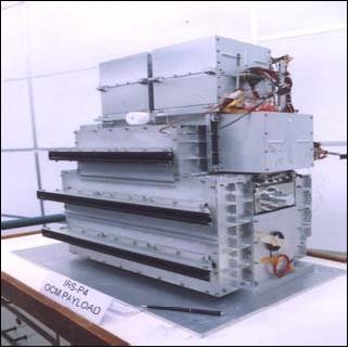
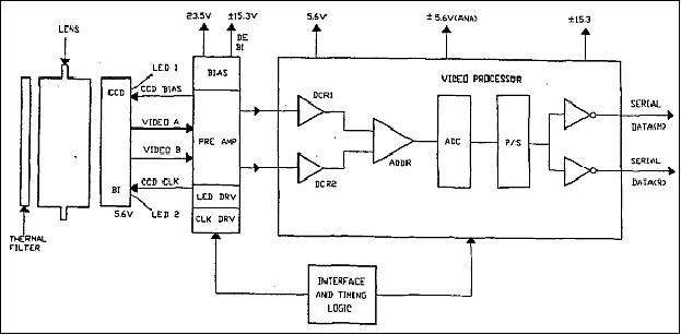
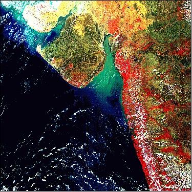
OCM provides multi-spectral imagery with narrow spectral width having large field of view of ±43º and ground resolution of 360 m. The sensor is designed to cater to land and ocean applications globally and accordingly it has high radiometric sensitivity with large dynamic range. The radiometric performance is realized using low noise circuit designs and practices. The optics and detectors are mounted on a highly stable structure, which facilitates achieving band-to-band registration, minimizes veiling glare and temperature excursions and avoids sun glints. 11)
OCM is a solid-state radiometer providing observations in eight spectral bands in the VNIR region (nm): B1: 402-422, B2: 433-453, B3: 480-500, B4: 500-520, B5: 545-565, B6: 660-680, B7: 745-785, and B8: 845-885. The instrument employs pushbroom scanning technology with linear CCD detector arrays (191 6K CCD) of 6000 elements (3700 active detectors, the rest are used to correct for dark current). A swath of 1440 km is provided. An along-track instrument tilt capability of ±20º is provided to avoid sun glint. OCM optics is based on one lens per band (wide angle telecentric lens design, refractive system). A scheme of using unused CCD pixels is being utilized as a reference for calibration. The ground resolution is 360 m in the along-track and 236 m in the cross-track direction. Applications are: 12) 13) 14)
• Measurement of concentrations of phytoplankton pigments, suspended sediments, Gelbstoff concentration in the euphotic layer. Assessment of their distribution, both spatially and temporally; detection of algal blooms and their dynamic behavior.
• Identification of potential fishery zones
• Delineation of coastal currents and eddies
• Estimation of optical properties and phytoplankton abundance for marine resource and habitat assessment
• Observation of pollution and sediment inputs to the coastal zone and their impact on marine food
• Sediment dynamics, dynamics of estuarine/tidal inlets, prediction of shoreline changes, coastal circulation and dispersion patterns.
Parameter | Value | Parameter | Value |
Spectral range (8 bands) | 0.4 - 0.9 µm (VNIR) | SNR | > 512 (saturation) |
Scan plane tilt | ±20º,to avoid sun glitter | Effective focal length | 20 mm |
Camera MTF | >20% at Nyquist frequency | Absolute radiometric accuracy | <10% |
IFOV at nadir (spatial resolution) | 360 m x 236 m (VNIR) | No of CCD elements | 6000 |
FOV (swath) | 1420 km (±43º) | CCD element size | 10 µm x 7 µm |
Tilt capability | ±20º along track | Integration time | 52.4 ms |
Data quantization | 12 bit | Exposure levels (gain) | 16 |
Data rate (real-time) | 20.8 Mbit/s | Onboard calibration | 2 LEDs per band |
The two modes of OCM data transmission are real-time and playback. The playback mode provides a coarser spatial resolution of 2.16 km. The data are averaged onboard (8 scan lines x 4 pixels) and transmitted in the eclipse phase of the orbit at a rate of 0.3 Mbit/s. The instrument mass is 78 kg, power = 134 W, size: 701 mm x 527 mm x 470 mm.
The imaging concept of OCM is an extension of the imaging concept adopted for the IRS LISS instruments. Unlike SeaWiFS or OCTS, OCM does not have common collecting optics coupled to a scan mechanism for realizing the wide swath. OCM has separate wide-angle refractive optics and a linear array CCD detector for each band. The issue of spectral response variation with large incidence angles is overcome by the choice of a telecentric design and the use of a spectral selection filter close to the linear array detector. - The pushbroom approach has enabled the use of a 12 bit digitizer to cover the instruments dynamic range. 15)
Band | Band center and bandwidth (nm) | Saturation radiance (mW cm-2 sr-1 µm-1) | Applications | NESR (mW cm-2 sr-1 µm-1) |
B1 | 412, 20 | 35.5 | Yellow substance and turbidity | 0.026 |
B2 | 442, 20 | 28.5 | Chlorophyll absorption | 0.022 |
B3 | 489, 20 | 22.8 | Chlorophyll and other pigments | 0.017 |
B4 | 512, 20 | 25.7 | Turbidity, suspended sediment | 0.017 |
B5 | 557, 20 | 22.4 | Chlorophyll, suspended sediment | 0.015 |
B6 | 670, 20 | 18.1 | Chlorophyll absorption | 0.01 |
B7 | 768, 40 | 9.0 | O2 absorption | 0.005 |
B8 | 867, 40 | 17.2 | Aerosol optical thickness, vegetation, water vapor reference over the ocean | 0.008 |
While only about 20% of the signal received by the OCM optics on orbit comprises ocean radiance, 80% is the contribution from intervening atmosphere. Thus, to extract information on ocean color, the contribution from the atmosphere needs to be eliminated. Hence, correction is being carried out by using data from bands 7 and 8. - The sun glint problem is being dealt with by tilting the instrument by an angle of ±20º. Its position can be fixed according to the latitude of observation and season. The tilt mechanism of OCM ensures a glint-free observation anywhere on the globe.
MSMR (Multifrequency Scanning Microwave Radiometer)
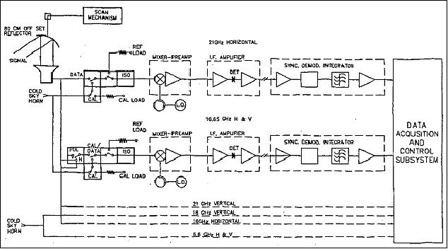
Objective: to complement the biological ocean parameters of OCM with some geophysical parameters such as: sea surface temperature (SST), sea surface wind speed (SSW), atmospheric water vapor (WV), and cloud liquid water content (CLW). MSMR is a dual-polarized four-frequency radiometer measuring microwave brightness temperature. It features a conical scanning mechanism with a constant look angle of 43.13º and a scan rate of 11.16 rpm. The various receivers are Dicke-switched with a two-point onboard calibration using hot termination and a cold-space horn antenna. The eight-channel MSMR employs six independent receivers 6.6, 10.6, 18, 21 GHz. MSMR observations are continuous over the mission life. Instrument mass = 65 kg, power = 76 W, the data rate is 6.4 kbit/s. 16) 17)
Parameter | Value | Parameter | Value |
Frequencies (GHz) | 6.6, 10.65, 18, 21 | Antenna diameter | 0.862 m x 0.800 m |
Polarization | V&H, V&H, VH, VH | 3 dB beam width | 4.2º, 2.6º, 1.6º, 1.4º |
Swath width | 1360 km | Spatial resolution (km) | 105x68, 66x43, 40x26, 34x22 (for frequency sequence) |
Sampling interval | 9 ms | Temperature resolution | <1.0 K |
Data quantization | 12 bit | Dynamic temp. range | 3.7 - 330 K |
MSMR has an antenna reflector of size 860 mm x 800 mm, an off-axis parabola, and a corrugated feed to receive the emitted radiation from the Earth and its atmosphere. The antenna reflector is rotated at 11.16 rpm to get a circular scan of 1360 km on the Earth's surface with a constant incidence angle of 49.7º. The receiver signal is detected by a square-law detector and synchronously demodulated. The amplitude of the incoming signals are quite low and hence very sensitive to the temperature stability of the components (often a fraction of a degree). To overcome this difficulty, an onboard calibration scheme has been implemented wherein for each antenna scan, temperature values of critical components are recorded along with payload data. These data are used along with look-up tables on the ground to compensate for the temperature variations onboard, thus improving the determination of the brightness temperature. The MSMR instrument provides a two-day repetivity thus providing applications in fisheries, meteorology, sea-state, etc. Research applications, like rainfall, soil moisture, and snow cover are also being tested.
The following data products of MSMR are generated on a routine basis:
• Level 0 antenna temperature data
• Level 1 brightness temperature data
• Level 2 geophysical parameter data
The MSMR realization required the following indigenous technical developments: a) a multifrequency polarization feed with a frequency ratio of 1:3.2; b) microwave blackbody targets with an emissivity>99.9% complete with cryogenic control; c) a precision thermistor-based temperature sensor with an accuracy of 0.1 K and a precision of 0.01 K.
Parameter | Channel | Accuracy | Resolution | Value Range |
WV | 21 with 18 & 10 (H&V) | 0.3 g/cm2 | 50 km x 36 km | 0.2 - 7.5 g/cm2 |
CLW | 21 with 18 & 10 (H&V) |
| 50 km x 36 km | 0 - 80 mg/cm2 |
SSW | 10 with 6.6, 18 & 21 (H&V) | 1.5 m/s | 75 km x 75 km | 2 - 24 m/s |
SST | 6.6 with 10, 18, & 21 (H&V) | 1.5 K | 150 km x 146 km | 273 - 303 K |
References
1) R. N. Tyagi, “IRS-P4 mission,” Current Science, Vol. 77, No 8, Oct. 25, 1999, pp. 1033-1037; also at URL: [web source no longer available]
2) M. Rao, V. Jayaraman, G. Joseph, “Earth Observation Programme of India - Catering to National Needs of Sustainable Development,” Proceedings of the International Symposium on Earth Observation System for Sustainable Development, Feb. 25-27, 1998, Bangalore, India, pp. 277-292
3) R. N. Tyagi, “Indian Remote Sensing Satellite (IRS)-P4 (OCEANSAT-1), NNRMS Bulletin 22, May 1998, pp. 5-12
4) ISRO brochure of IRS-P4 (OceanSat-1), provided by George Joseph
5) SAC Courier, Vol. 24, No 2, July 1999, the issue focuses on IRS-P4 (OceanSat-1), instruments and applications
6) IRS-P4 (OceanSat), ISRO, URL: http://www.isro.org/satellites/irs-p4_oceansat.aspx
7) S. Ramakrishnan, R. N. Tyagi, S. S. Balakrishnan, Sojan Thomas, “PSLV-C2 mission,” URL: [web source no longer available]
8) A. S. Ganeshan, S. A. Rathnakara, et al., “Precise Position Determination of IRS-P4 Using GPS Measurements,” Journal of Spacecraft Technology, Vol. 10, No 1, Jan. 2000, pp. 16-24
9) M. Ambarisha Babu, J. R. Subramanian, P. Soma, S. K. Shivakumar, “Techniques adopted to sustain the data services from IRS-P4 mission under power crunch scenario,” 58th IAC (International Astronautical Congress), International Space Expo, Hyderabad, India, Sept. 24-28, 2007, IAC-07-C1.5.03
10) http://www.antrix.gov.in/eo_oceansat_1.html
11) P. Rameshchandra, S. Somya, D. Chirag, U. Satyaharischandrarao, P. Himanshu , B. Hemal, D. Manoj, S. Harish, “Ocean color monitor sensor,” Proceedings of SPIE, 'Remote Sensing of the Marine Environment,' Robert J. Frouin, Vijay K. Agarwal, Hiroshi Kawamura, Shailesh Nayak, Delu Pan, Editors, 64060D, Vol. 6406, Nov. 28, 2006
12) M. S. Kumar, A. S. Kumar, “Ocean Color Monitor (OCM) of IRS-P4,” NNRMS Bulletin-22, May 1998, pp.13-19
13) P. S. Desai, H. Honne Gowda, K. Kasturirangan, “Ocean research in India: Perspective from space,” Current Science, Vol. 78 No. 3, Feb. 2000, pp, 268-278
14) T. Srinivasa Kumar, “Update on OCM on Oceansat-I & Scheduled OCM on Oceansat-II,” URL: http://www.ioccg.org/sensors/ocm/Kumar%20-OCM.pdf
15) R. R. Navalgund and A. S. Kiram Kumar, “Ocean Color Monitor (OCM) on Indian Remote Sensing Satellite IRS-P4,” ISRO/SAC internal paper provided by George Joseph; also available at: URL: http://www.ioccg.org/reports/ocm/ocm.html
16) S. S. Rana, “Multifrequency Scanning Microwave Radiometer of IRS-P4,” NNRMS Bulletin-22, May 1998, pp.20-23
17) P. Chauhan, M. Mohan, S. Nayak, “Comparative analysis of ocean color measurements of IRS-P4 OCM and SeaWiFS in the Arabian Sea,” IEEE Transactions on Geoscience and Remote Sensing, Vol. 41, No. 4, April 2003, pp. 922-926