IRS-P5 (Indian Remote Sensing Satellite-P5) / CartoSat-1
EO
Mission complete
High resolution optical imagers
Land
Quick facts
Overview
| Mission type | EO |
| Agency | ISRO |
| Mission status | Mission complete |
| Launch date | 05 May 2005 |
| End of life date | 01 Jan 2019 |
| Measurement domain | Land |
| Measurement category | Multi-purpose imagery (land), Albedo and reflectance |
| Measurement detailed | Land surface imagery, Earth surface albedo |
| Instruments | PAN (Cartosat-1) |
| Instrument type | High resolution optical imagers |
| CEOS EO Handbook | See IRS-P5 (Indian Remote Sensing Satellite-P5) / CartoSat-1 summary |
Related Resources
CartoSat-1 - Formerly IRS-P5 (Indian Remote Sensing Satellite-P5)
IRS-P5 is a spacecraft of ISRO (Indian Space Research Organization), Bangalore, India. The objectives of the IRS-P5 mission are directed at geo-engineering (mapping) applications, calling for high-resolution panchromatic imagery with high pointing accuracies. The spacecraft features two high-resolution panchromatic cameras that may be used for in-flight stereo imaging.
Prior to launch, ISRO renamed the IRS-P5 spacecraft to CartoSat-1, to describe more aptly the application spectrum of its observation data. In this mission, the high resolution of the data (2.5 m GSD) is being traded at the expense of multispectral capability and smaller area coverage, with a swath width of 30 km. The data products are intended to be used in DTM (Digital Terrain Model)/DEM (Digital Elevation Model) generation in such applications as cadastral mapping and updating, land use as well as other GIS applications.
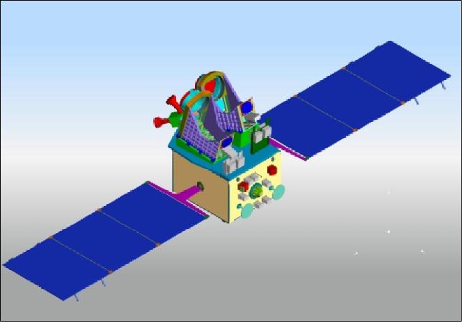
Spacecraft
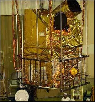
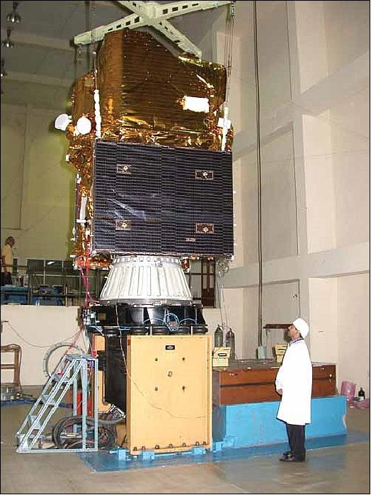
The spacecraft structure is of IRS-1C/1D and -P3 heritage, having a size of about 2.4 m x 2.7 m (height). The structure of the spacecraft consists of the MPL (Main Platform) and the PPL (Payload Platform). The MPL consists of main cylinder assembly, four vertical panels, top deck and bottom deck. The cylinder assembly comprises of a central load bearing cylinder, satellite interface ring and top ring. The top ring of the cylinder interfaces with the top deck. All the four panels consist of a CFRP cone, PPL deck, wedges for camera mounting, bracket to mount the payload electronic package near to the Detector Head assembly, and star sensor mounting wedge. The CFRP interface cone isolates the PPL Deck and the MPL. The two cameras are encompassed within a thermal cover assembly with two hoods and anchored to the PPL deck.
AOCS (Attitude and Orbit Control Subsystem): The platform is three-axis stabilized (star sensors in loop, magnetic bearing reaction wheels in tetrahedral configuration, 16 nozzles with 1 N thrusters, 4 nozzles with 11 N thrusters). The pointing accuracies are ±0.05º in all axes, attitude knowledge = 0.01º, the stability (attitude drift) is 5 x 10⁻⁵ º/s, and the ground location accuracy is < 220 m. The S/C provides a body-pointing capability in the cross-track direction to facilitate a better observation coverage of points of interest, the FOR (Field of Regard) is ±26º. The AOCS employs a MIL-STD 31750 processor.
Also, first demonstration of orbit determination on an ISRO satellite with a GPS receiver. Use of two SPS (Standard Positioning System) units to provide an instantaneous GPS-navigational solution for the spacecraft. The GPS-based Onboard Orbit Determination Software (GOODS) filters the instantaneous solutions from SPS using a constant gain filter. The software provides updated state vectors at regular instants of time. The measurement and state to be estimated are the same. - The SPS on board the IRS satellites provides the measurements, state vector in ECEF (Earth Centered Earth Fixed) WGS84 coordinate system. These state vectors need to be transformed to ECI (Earth Centered Inertial Coordinate System).
EPS (Electrical Poer Subsystem): A power of about 1.1 kW (EOL) is provided. The power subsystem of Cartosat-1 consists of six deployable solar panels, with three panels in each wing (sun side and anti sun side), each panel of size 1.4 m x 1.8 m. A SADA (Solar Array Drive Assembly) is employed for maximum power tracking. Two NiCd batteries, each of 24 Ah capacity, provide power during the eclipse phases of the orbit. The power bus is formed by ohmic interconnection of solar array strings (current source) and battery (voltage source). There are two raw bus lines called Bus-A and Bus-B. The raw bus is essentially the battery whose voltage ranges from 28 - 42 V. Bus control is by PWM based TCR (Taper Charge Regulator).
RCS (Reaction Control Subsystem): The RCS of Cartosat-1 is a monopropellant hydrazine system using nitrogen as pressurant and operating in a blow-down mode. The RCS is used for correcting the satellite injection errors in attitude and inclination, attitude acquisition and maintenance of the desired sun synchronous orbit. Eight nozzles of 1 N and four 11 N thrusters are mounted on the bottom deck.
The Thermal control subsystem maintains the temperature of different subsystems within the specified limits using semi-active and active thermal control elements like paints, MLI (Multi Layer Insulation) blankets, optical solar reflectors and auto-temperature controllers All the surfaces of PAN cameras are thermally treated with black paint. All MFD (Mirror Fixing Devices) are provided with black tapes. The payload CCD cold finger is connected to heat pipe by a copper braid. Each CCD has one heat pipe which runs over the thermal cover and get attached to the sun side radiator plate and anti-sun side radiator plate respectively.
The spacecraft launch mass is about 1560 kg (including fuel). A total of 131 kg of hydrazine mono-propellant is used to provide a minimum mission life of 5 years. The spacecraft was designed and built at ISAC (ISRO Satellite Center), Bangalore, India, as the lead center of CartoSat-1, with contributions from SAC (Space Applications Center), Ahmedabad. 1) 2) 3) 4) 5) 6) 7) 8)
Spacecraft launch mass | 1560 kg |
Spacecraft design life | 5 years with a goal of 7 years |
Spacecraft power | 1.1 kW (EOL) |
AOCS (Attitude and Orbit Control Subsystem) | 3-axis body stabilized using reaction wheels, magnetic torquers and hydrazine thrusters |
Payload data transmission | X-band, 2 strings each at 105 Mbit/s |
On-board data storage capacity | 120 Gbit |
Payload mass (2 PAN cameras) | 200 kg |
Launch
A launch of the CartoSat-1 (alias IRS-P5 ) spacecraft took place on May 5, 2005. The launch was on a PSLV launch vehicle (PSLV-C6) of ISRO from the SDSC (Satish Dhawan Space Centre) Sriharikota launch site on the east coast of India. 9) 10)
A secondary payload on this flight was Hamsat (VUSat) of AmSat India with a launch mass of 43.5 kg. Hamsat carries two transponders in UHF band to provide spaceborne radio amateur services to India and the international Ham radio community.
RF communications of CartoSat-1: Payload data transmission is in X-band (2 carriers, one for each camera, QPSK modulated, single polarized), each channel at 105 Mbit/s. A new electronically steerable beam phased-array antenna system has been implemented to transmit the payload data. An onboard solid-state recorder of 120 Gbit capacity is used for payload data recording (up to 9.5 min of observations).
The TT&C subsystem is in S-band and is comprised of a TT&C transponder. The TT&C data are transmitted at 1 kbit/s in nominal mode and at 16 kbit/s in playback mode.
The TT&C transponder transmits the telemetry data, receives the telecommand signals, demodulates the ranging tones and re-transmits them to ground with a fixed turn around ratio of 240/221 to enable measurement of two-way Doppler. The Transponder system consists of receiving and transmitting system and can operate in a coherent or non coherent mode. In coherent mode, the downlink carrier is derived by PLL technique from the uplink signal. In non-coherent mode, the downlink carrier is derived from an independent TCXO (Temperature Controlled Crystal Oscillator).
Orbit: Sun-synchronous circular orbit, altitude = 618 km, inclination =97.87º, period of 97 min, nodal equatorial crossing time on ascending node at 10:30 hours. The orbital revisit cycle is 126 days. However, a revisit capability of 5 days is provided by the body-pointing feature of the spacecraft about its roll axis by ±26º.
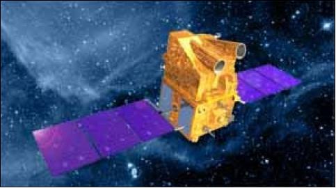
Mission Status
• The CartoSat-1 spacecraft and its payload are operating nominally in 2012. CartoSat-1 is completing its 7th year on orbit in May 2012 and is being routinely operated; it is returning high quality data. 11)
• The CartoSat-1 spacecraft and its payload are operating nominally in 2011. 12)
• The CartoSat-1 spacecraft and its payload are operating nominally in 2010. 13)
• GAF/Euromap, the European commercial distributor of CartoSat-1 imagery, developed in concert with DLR a DEM (Digital Elevation Model), mainly for Europe. 14)
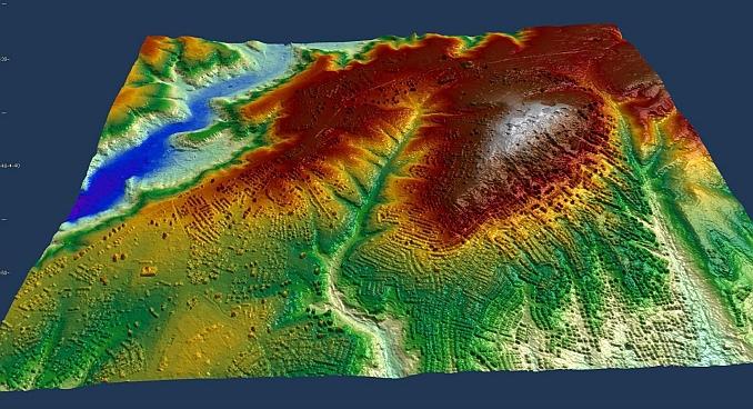
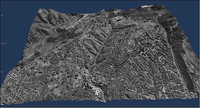
• In 2006 and 2007, the IGP (Institute of Geodesy and Photogrammetry) at ETH Zürich (Switzerland) in collaboration with ISRO performed a CartoSat-1 evaluation program for the geometric validation of the CartoSat-1 imagery. Several test sites were investigated [Catalonia test site (Spain), Sakurajima testfield (Japan)]. 15)
Sensor Complement
PAN
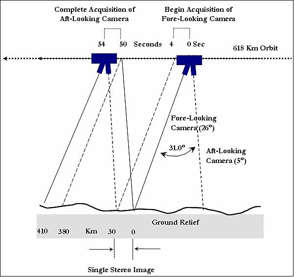
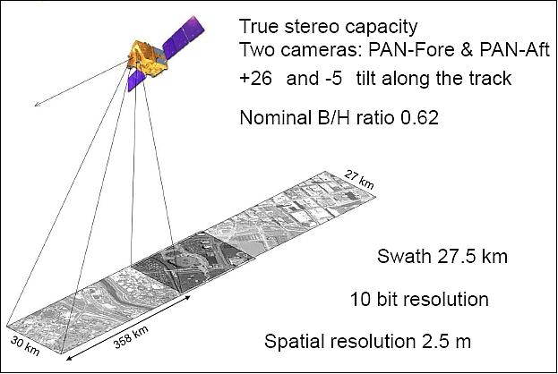
The payload instrumentation consists of two panchromatic cameras of PAN heritage as flown on the IRS-1C/D satellites. The objective is to obtain fore-aft stereo imagery with two fixed (body-mounted) instruments (i.e., a two-line stereo configuration). The discrimination of elevation differences of better than 5 m make the data particularly suitable for map-making and terrain modeling (Ref. 6). 16) 17) 18) 19) 20)
• PAN-F i(Panchromatic Forward-pointing Camera) featuring a fixed forward tilt of 26º.
• PAN-A (Panchromatic Aft-pointing Camera), it is fixed at an aft tilt of -5º.
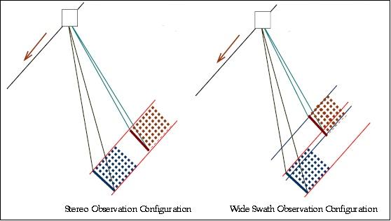
Each camera provides a spectral range of 0.5 - 0.85 µm, a spatial resolution of 2.5 m, a swath width of 30 km, and data quantization of 10 bits. Stereo imagery is acquired with a small time difference (about 50 s) due to the forward and backward look angles of the two cameras. The major change in imaging conditions during this time period is due to rotation of Earth. An algorithm for Earth rotation compensation is being used to eliminate the delayed observations of the two cameras.
Aside from stereo observations, the two cameras may also be used for wide swath mode acquisitions (Figure 7).
Parameter | PAN-F Camera | PAN-A Camera |
Spectral range | 500 - 850 nm | 500 - 850 nm |
Along-track tilt angle with respect to nadir | +26º | -5º |
Spatial resolution (cross-track x along-track) | 2.5 m x 2.78 m | 2.22 m x 2.23 m |
Radiometric resolution |
55 mW/(cm2 sr µm) | |
Swath width (for stereo imagery) | 29.42 km | 26.24 km |
Swath width (for monoscopic observation mode) | 55 km (with swath overlaps) | |
CCD array (No of arrays x No of elements) | 1 x 12,288 | 1 x 12,288 |
Optics: |
| |
Integration time | 0.336 ms | |
MTF (Modulation Transfer Function) | cross-track = 20, along-track = 23 | |
Onboard calibration | Relative, using LEDs | |
Data compression | JPEG algorithm, compression ratio = 3.2 (max) | |
Data rate | 105 Mbit/s (source data rate of 340 Mbit/s) | |
Nominal B/H ratio for stereo | 0.62 | |
The onboard source data rate of each camera is 336 Mbit/s. An onboard ADPCM/JPEG compression algorithm of 3.2 : 1 is applied reducing the data rate to 105 Mbit/s (i 52.5 + q 52.5) for each camera.
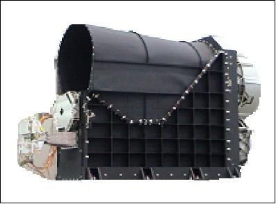
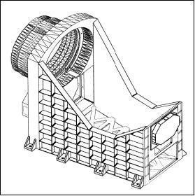
The optical system of each PAN camera is designed with a three-mirror off-axis reflective telescope with an off-axis concave hyperboloidal primary mirror and an off-axis concave ellipsoidal tertiary mirror - to meet the required resolution and swath width. The mirrors are made from special Zerodur glass blanks and are light weighted. The mirrors are are polished to an accuracy of l/80 and are coated with enhanced AlO2coating. The mirrors are mounted to the electro-optical module using iso-static mounts, so that the distortion on the light weighted mirrors are reduced to a minimum. The configuration of the electro-optical module of the camera is shown in Figure 11. Each camera features a linear CCD detector array of 12,288 pixels. The overall size of each PAN camera is 150 cm x 850 cm x 100 cm with a mass of 200 kg.
The imagery of the 2-line along-track stereo camera may be used for a variety of applications, among them for the generation of DEMs (Digital Elevation Models). The data is expected to provide enhanced inputs for large scale mapping applications and stimulate newer applications in the urban and rural development.
Ground Segment
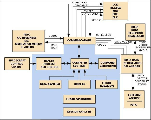
The spacecraft is being operated by ISTRAC (ISRO Telemetry, Tracking and Command Network) of Bangalore, using its its network of stations at Bangalore, Lucknow, Mauritius, Bearslake in Russia and Biak in Indonesia. NRSA (National Remote Sensing Agency) of Hyderabad is receiving the payload data and is the processing center for the CartoSat-1 mission.
The payload data acquisition is performed at the NRSA ground station, located at Shadnagar, near Hyderabad.
Data Products Generation
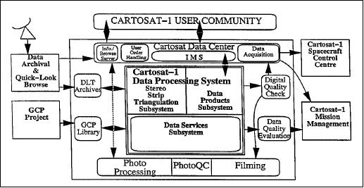
The main elements of the CartoSat-1 data products generation facility are shown in Figure 13.
• DAQLB (Data Archival and Quicklook Browser)
• DPS (Data Processing System)
• CDC (CartoSat Data Center)
GeoEye (formerly Space Imaging Inc. of Thornton, CO, USA) has a sales and marketing agreement through 2010 with Antrix Corporation, a division of ISRO, which covers worldwide rights to sell imagery outside of India.
CartoSat-1 data products are of two categories: (Ref. 4)
• Standard product (radiometrically corrected, georeferenced)
• Precision product (ortho rectified product).
Standard products are generated after accounting for radiometric and geometric distortions while precision products are ortho rectified. Ortho rectified products are corrected for terrain distortions and camera tilt effects with the help of control points and using Stereo Strip Triangulation (SST) based DEM (only for Indian region). All CartoSat-1 data products are supplied with 10 bit radiometry for both PAN Fore and Aft cameras.
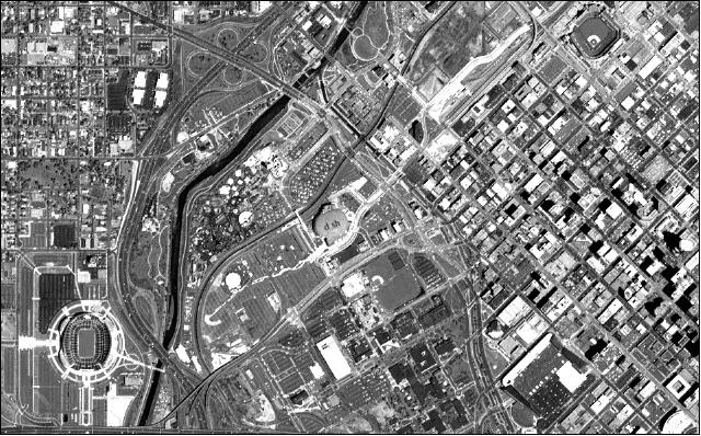
Stereo imaging from space-borne platforms offers information about terrain elevation besides supplying spectral reflectance of the scene. This greatly assists the analysis and interpretation of images in terms of identifying slopes, surface material, waterways, vegetation growth, etc. Applications like urban planning, agriculture, defense etc., need to use Digital Elevation Model (DEM) derived from stereo images, which is an important component of geospatial data. 21) 22) 23) 24)
IRS Data Distributors
Through several data reception agreements with Antrix, the commercial arm of ISRO, Euromap (Euromap Satellitendaten-Vertriebsgesellschaft mbH, Neustrelitz, Germany) became the first and only actor in Europe to successfully receive, archive and market Indian Earth observation satellite data. Current agreements with Antrix and EOTec (EOTec serves as managing agent for Antrix) grant Euromap the right to receive and exclusively distribute data from IRS-P6 (ResourceSat-1) and IRS-P5 (CartoSat-1) in Europe, including Turkey, and northern Africa. 25) 26) 27)
Through recent agreements with the European Space Agency (ESA), historical (IRS-1C, IRS-1D) and recent (Resourcesat-1, Cartosat-1) worldwide IRS data and related services are made available to the GMES user community. Through Euromap, the IRS program significantly contributed to activities like Image2006, Image2009 and MARS (Monitoring Agriculture with Remote Sensing).
The German Aerospace Center (DLR) is Euromap’s long-term partner regarding reception and archiving activities, as well as the development of interfaces towards ESA.
The data reception is performed through DLR’s German Remote Sensing Data Center (DFD) at its multi-mission ground station in Neustrelitz, approximately 100 km north of Berlin. Besides data from several other missions received for other clients, DFD currently receives data from IRS-P6 (ResourceSat-1) and IRS-P5 (CartoSat-1) for Euromap.
As Antrix’s partner in Europe, Euromap is responsible for the acquisition planning, reception, archiving, processing, marketing and distribution of IRS data.
References
1) http://www.gisdevelopment.net/technology/rs/techrs023a.htm
2) M. Krishnaswamy, “Sensors and Platforms for High Resolution Imaging for Large Scale Mapping Applications - Indian Scenario,” Indian Cartographer, 2002, DAPI-01, URL: http://www.scribd.com/doc/51510618/cartosat
3) M. Krishnaswamy, S. Kalyanaraman, “Indian Remote Sensing Satellite CartoSat-1: Technical features and data products,” http://www.gisdevelopment.net/technology/rs/techrs023.htm
4) “CartoSat-1 - A global IRS Mission for large scale mapping and Terrain Modeling applications,” NRSA (National Remote Sensing Agency) Data Center, Hyderabad, India, URL: http://bhuvan-noeda.nrsc.gov.in/download/download/tools/document/Cartosat_1_brochure.pdf
5) http://www.isro.org/satellites/cartosat-1.aspx
6) “CartoSat-1 Data User's Handbook,” NRSA (National Remote Sensing Agency), Sept. 2006, URL: http://gmesdata.esa.int/geonetwork_gsc/srv/en/resources.get?id=142&fname=P5_data_user_handbook.pdf&access=private
7) V. Lakshminarayana, V. K.Hariharan, K. S. Dayashankara, A. K. Shrivastava, N. D. Ghatpande, T. L. Danabalan, “Assessment and control of electromagnetic interference in CartoSat-1 spacecraft,” Proceedings of the 9th International Conference on ElectroMagnetic Interference and Compatibility (INCEMIC), Bangalore, India, Feb. 23-24, 2006
8) V. K. Hariharan, N. S. Sundaram, K. S. Dayashankara, V. Lakshminarayana, A. K. Shrivastava, A. Damodaran, L. N. Gupta, P. P. Ganeshan, M. Velayudhan, B. V. Rao, N. D. Ghatpande, T. L. Danabalan, “Assembly, integration and testing of CartoSat-1,” Proceedings of the 9th International Conference on ElectroMagnetic Interference and Compatibility (INCEMIC), Bangalore, India, Feb. 23-24, 2006
9) CartoSat-1, ISRO, URL: http://www.isro.org/satellites/cartosat-1.aspx
10) CartoSat-1 And Hamsat To Be Launched By PSLV-C6 On Thursday,” Space Daily, May 4, 2005, URL: http://www.spacedaily.com/news/eo-05zq.html
11) Information provided by A. S. Kiran Kumar of ISRO/SAC, Ahmedabad, India
12) Information provided by Frithjof Barner of GAF/Euromap, Germany
13) Information provided by Rupert Haydn of GAF, Munich, Germany
14) Information provided by Sebastian Carl of GAF/Euromap, Germany
15) S. Kocaman, K. Wolff, A. Gruen, E. Baltsavias, “Geometric Validation of CartoSat-1 Imagery,” The International Archives of the Photogrammetry, Remote Sensing and Spatial Information Sciences. Vol. XXXVII. Part B1. Beijing 2008, URL: http://www.isprs.org/proceedings/XXXVII/congress/1_pdf/230.pdf
16) M. Krishnaswamy, S. Kalyanaraman, “Indian Remote Sensing Satellite CartoSat-1: Technical features and data products,” URL: http://www.gisdevelopment.net/technology/rs/techrs023.htm
17) R. S. Ramayanam, “Indian Remote Sensing Satellites ResourceSat-1 (IRS P6) & CartoSat-1 (IRS P5),Data Availability,” URL: http://www.pecad.fas.usda.gov/pdfs/USDA_Workshop_Presentation2_DrRao.pdf
18) http://www.euromap.de/docs/doc_004.html
19) Gayla A. Evans, Bhaskar Ramachandran, Zheng Zhang, G. Bryan Bailey, Philip Cheng, “An Accuracy Assessment of CartoSat-1 Stereo Image Data-Derived Digital Elevation Models: A Case Study of the Drum Mountains, Utah,” The International Archives of the Photogrammetry, Remote Sensing and Spatial Information Sciences. Vol. XXXVII. Part B1. Beijing 2008, URL: http://www.isprs.org/proceedings/XXXVII/congress/1_pdf/198.pdf
20) D. Subrahmanyam, Saji A. Kuriakose, Pradeep Kumar, Jaimin Desai, Barkha Gupta, B. N. Sharma, “Design and development of the Cartosat payload for IRS P5 mission,” Proceedings of SPIE, 'Multispectral, Hyperspectral, and Ultraspectral Remote Sensing Technology, Techniques, and Applications,'. Edited by William L. Smith, Sr.; Allen M. Larar; Tadao Aoki; Ram Rattan, Volume 6405, 2006, pp. 640517, DOI: 10.1117/12.693860
21) Pradeep K. Srivastava, T. P. Srinivasan, Amit Gupta, Sanjay Singh, Jagjeet Singh Nain, Amitabh, Shilpa Prakash, B. Kartikeyan, B. Gopala Krishna, “Recent Advances in CartoSat-1 Data Processing,” ISPRS Hannover Workshop 2007: 'High-Resolution Earth Imaging for Geospatial Information,' May 29-June 1, 2007, URL: http://www.ipi.uni-hannover.de/fileadmin/institut/pdf/Srivastava_etal.pdf
22) Nadeem Ahmed, Anjum Matab, Ritesh Agraval, P. Jayaprasad, S. K. Pathan, Ajai, D. K. Singh, A. K. Singh, “Extraction and validation of CartoSat-1 DEM,” Journal of the Indian Society of Remote Sensing, Volume 35, No 2, June 2007, pp. 121-127
23) Marco Gianinetto, “Evaluation of CartoSat-1 Multi-Scale Digital Surface Modelling Over France,” Sensors 2009, Vol. 9, pp. 3269-3288; doi:10.3390/s90503269, URL: http://www.mdpi.com/1424-8220/9/5/3269/pdf
24) P. V. Radhadevi, V. Nagasubramanian, Mahapatra Archana , S. S. Solanki, Sumanth Krishna, Varadan Geeta, “Potential of High-resolution Indian Remote Sensing Satellite Imagery for Large Scale Mapping,” ISPRS Hannover Workshop 2009, 'High-Resolution Earth Imaging for Geospatial Information,' June 2-5, 2009, Hannover, Germany, URL: http://www.isprs.org/proceedings/XXXVIII/1_4_7-W5/paper/Radhadevi-153.pdf
25) Frithjof Barner, Rupert Haydn, Holger Maass, L. N. Remilla Murthy, “Contribution of the Indian IRS Program to the European Data Requirements through Euromap,” ESA Living Planet Symposium, Bergen, Norway, June 28 to July 2, 2010, Special Publication SP-686, URL: http://www.euromap.de/pdf/1872905_Barner_ConIRSEUDataReqEM_v1.1_20100628.pdf
26) ANTRIX Corporation Limited (India) and Euromap GmbH (Germany) Further Expand Cooperation with New Agreement for CartoSat-1 Satellite Data Reception and Distribution,” January 14, 2008, URL: http://www.gaf.de/.../pr_germany_euromap_antrix_01-2008.pdf
27) http://www.antrix.gov.in/irsonline/eosatellites.html
The information compiled and edited in this article was provided by Herbert J. Kramer from his documentation of: ”Observation of the Earth and Its Environment: Survey of Missions and Sensors” (Springer Verlag) as well as many other sources after the publication of the 4th edition in 2002. - Comments and corrections to this article are always welcome for further updates (eoportal@symbios.space).