Kometa Space Mapping System
EO
Ocean
Multi-purpose imagery (ocean)
ROSKOSMOS
Quick facts
Overview
| Mission type | EO |
| Agency | ROSKOSMOS |
| Mission status | Mission complete |
| Launch date | 18 Feb 1981 |
| End of life date | 14 Nov 2000 |
| Measurement domain | Ocean, Land |
| Measurement category | Multi-purpose imagery (ocean), Multi-purpose imagery (land) |
| CEOS EO Handbook | See Kometa Space Mapping System summary |
Kometa Space Mapping System (1981-2000) based on Film Recovery
Overview
Kometa is a wide-area photoreconnaissance program of Russia (former USSR) which started in 1981 to conduct high-precision topographic surveys. These short-duration mission spacecraft typically remain in orbit for 40-45 days and are distinguished by their relatively circular orbits between 195 and 280 km. Kometa missions were always launched from the Baikonur Cosmodrome in Kazakhstan on Soyuz launch vehicles into inclinations of 65º or 70º at the rate of one or two per year. 1)
Applications: Remote sensing data acquired by “Kometa” spacecraft serves for a variety of applications, such as production and updating of topographic maps, production of larger scale maps, digital maps, DEM, land and forestry cadastre, land use control, water resources management, etc.
Spacecraft
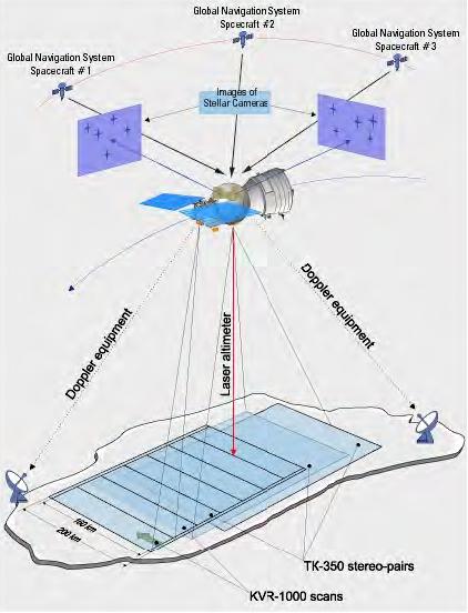
The Russian Kometa spacecraft is a variation of the Yantar-class spacecraft (Yantar-1KFT, designed and developed by TsSKB Progress, of Samara) with a total satellite mass of about 6,600 kg. The onboard equipment includes two star positioning cameras, a laser altimeter, navigation sensors and synchronizing devices. In order to obtain synchronized operation, and to provide the required accuracy, all the hardware is integrated into the common system based on constructional, accuracy and timing parameters.
Background: The Yantar military spacecraft program originated in 1972 at TsSKB (Central Specialized Design Bureau), Samara, USSR [there is also the spelling of: TsNII Kometa (Central Scientific Research Institute Kometa)]. The first Yantar-1KFT was launched from the Baikonur cosmodrome on Feb. 18, 1981 under the official name of Cosmos-1246. The mission lasted for 23 days. The following missions of the satellites of this series, as a rule, lasted for 44-45 days. After the seventh mission on July 22, 1987 the system was adopted for use and designated “Kometa.”
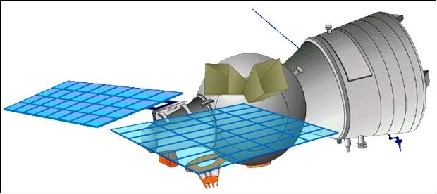
Figure 1: Illustration of the Kometa satellite (image credit: Sovinformsputnik)
Launch
Cosmos-2373, also known as Kometa 20, was launched on Sept. 29, 2000, the last of the Kometa series spacecraft. The initial orbital parameters were: period of 89 min, apogee of 265 km, perigee of 185 km, and inclination 70.37º. After a day it raised its orbit to 211 km x 285 km, inclination of 70.37º. The satellite is the 20th Kometa mapping payload. It was announced as a dual civil-military geodetic mission.
Kometa No | Launch date | Designation of flight | Orbit | Mission length |
1 | Feb. 18, 1981 | Cosmos 1246 | 193 km x 263 km, 64.9º | 23 days |
2 | May 28, 1982 | Cosmos 1370 | 195 km x 273 km, 64.9º | 44 days |
3 | Dec. 27, 1983 | Cosmos 1516 | 194 km x 274 km, 64.9º | 49 days |
4 | Nov. 14, 1984 | Cosmos 1608 | 195 km x 248 km, 70.0º | 33 days |
5 | Aug. 08, 1985 | Cosmos 1673 | 195 km x 271 km, 64.8º | 42 days |
6 | Oct. 06, 1986 | Cosmos 1784 | 190 km x 283 km, 64.8º | 36 days |
7 | July 08, 1987 | Cosmos 1865 | 192 km x 297 km, 64.8º | 37 days |
8 | Nov. 14, 1987 | Cosmos 1896 | 206 km x 263 km, 64.8º | 41 days |
9 | May 19, 1988 | Cosmos 1944 | 196 km x 288 km, 64.8º | 36 days |
10 | Dec. 29, 1988 | Cosmos 1986 | 193 km x 289 km, 64.8º | 44 days |
11 | May 24, 1989 | Cosmos 2021 | 204 km x 280 km, 69.9º | 43 days |
12 | May 15, 1990 | Cosmos 2078 | 196 km x 280 km, 70.0º | 44 days |
13 | Feb. 15, 1991 | Cosmos 2134 | 190 km x 306 km, 64.7º | 45 days |
14 | Dec. 17, 1991 | Cosmos 2174 | 193 km x 306 km, 64.7º | 44 days |
15 | Apr. 29, 1992 | Cosmos 2185 | 209 km x 274 km, 70.0º | 43 days |
16 | Apr. 27, 1993 | Cosmos 2243 | 189 km x 233 km, 70.0º | 9 days |
17 | Jul. 29, 1994 | Cosmos 2284 | 206 km x 296 km, 70.4º | 41 days |
18 | May 14, 1996 | Cosmos | Launch failure |
|
19 | Feb. 17, 1998 | Cosmos 2349 | 212 km x 327 km, 70.4º | 44 days |
20 | Sep. 29, 2000 | Cosmos 2373 | 211 km x 287 km, 70.37º | 46 days |
Orbit: A spacecraft of the Kometa series is launched into an orbit of about 70º inclination. The orbital near-circular altitude varies between 190 and 270 km, depending on the required object and duration of the mission (see Table 1).
Sensor Complement
TK-350 and KVR-1000
The onboard sensors are film cameras whose data (namely, the films) are recaptured after the end of each mission. The descent capsules are reused an average of three times. The film imagery is based on discrete frame-type imagery.
The Kometa spacecraft carry the conventional analog (film) photographic imaging systems. Despite great advances in optoelectronic camera systems (particularly in the 1990s), photographic camera systems continue to be used for cartographic applications because they are capable of providing a combination of both broad area coverage and high spatial resolution. The system allows topographic, digital, and thematic maps to be produced for any area of the Earth. Due to the optical design features and large swath capabilities of the camera systems, highly accurate and detailed imagery can be created for specific regions or for entire countries.
The total film capacity covers approximately 10.5 million km2 of surface area. The entire system is then retrieved from orbit and landed at the preliminary defined location. The film is then retrieved from the descending module, processed, converted into digital form using precise scanner systems (3600 dpi scanner); they are then ortho-rectified. The digital products are delivered to customers on CD-ROM in required format. 2)
• TK-350 stereo camera system (Yakhont-1), a large-format wide-angle camera with a Rusinov objective, produced by the Belarus (Belorussia) Optical Camera Company, with an Earth's surface FOV (Field-of-View) of 180 km x 270 km (also 200 km x 300 km of scene size depending on orbital altitude - and with a spatial resolution of 10 m) with 256 gray values. [Note: the 256 grey levels, as stated, might be misleading. This 8 bit quantization would be correct for a digital copy from the original negative, but not for the film itself. In an analog recording medium, the response of film is a continuum over its range of photographic density/exposure. The level of quantization possible with an image on film is subject to limitations due to resolving power, the MTF (Modulation Transfer Function), granularity and such considerations as the Wiener spectrum (after Norbert Wiener, 1894-1964) of the grain structure and wavelength of illumination used in scanning. All these characteristics being unique to a particular combination of camera, film and processing, as well as the scanner performance.] 3) 4) 5)
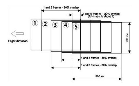
The TK-350 camera was designed for exceptional geometric precision for cartographic purposes. The system acquires fore-and-aft stereo pairs with an overlap of about 80%.. It features a relatively large frame size of 300 mm x 450 mm with a focal length of 350 mm. And with the 80% stereo overlap, the camera achieves a base/height ratio of 1:1, which results in extremely accurate ground points being extracted from the stereo pairs.
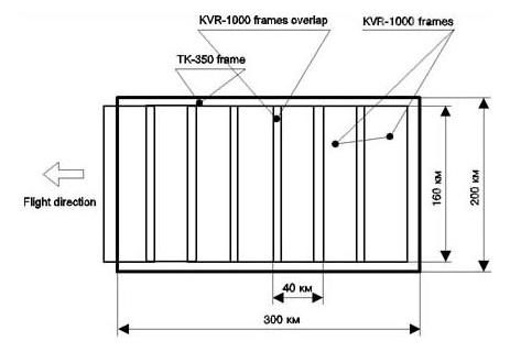
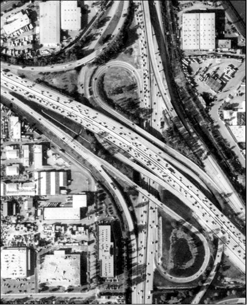
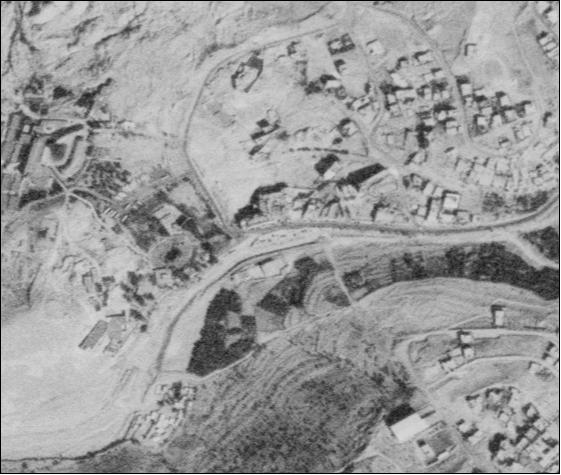
• KVR-1000 high-resolution camera system with 2 m resolution and a nominal image FOV of 40 km x 40 km (scene size of 40 x 160 km). The panoramic KVR-1000 camera design with the Apo-Okton-8 optical system employs two mirror systems (one for the cross-track pointing of about ± 20º, the other one for motion compensation in along-track), to illuminate the film frame format of size 18 cm (width) x 72 cm in length. A snapshot series with this system covers a ground scene of 40 km x 160 km with the long side of the image in the cross-track direction. There is only little overlapping of sequential imagery (since stereo coverage is provided by the TK-350 camera). Two KVR-1000 camera systems on a spacecraft are being activated alternatively to provide a ground coverage almost identical to that of the TK-350 camera. KVR-1000 imagery is used primarily for feature extraction applications in urban planning, parcel mapping, and agricultural monitoring.
The very high metric standard of photography obtained with the Kometa system permits mapping with a planimetric accuracy of 20-25 m and 10 m in height at a map scale of 1:50,000 where no ground control point (GCP) is available. With GCP, the planimetric mapping accuracy is 7-10 m and about 5 m in height at a scale of 1:25,000. When using KVR photography, a planimetric accuracy of 2-3 m can be achieved at 1:10,000 scale.
The TK-350 system is a topographic camera developed specifically to collect stereoscopic images for determination of ground relief (surveys). The camera is operated with the longer side of the format aligned with the satellite ground track (see Figure 4), this giving the base/height ratio in the stereo photography necessary for determining elevation differences in the terrain [the accuracy of (DEM) ground points significantly depends on the ratio of the photo base to the shooting height at the moment the image is acquired). With the stereo overlap of 80%, the camera achieves a base/height ratio of 1:1, which results in extremely accurate ground points being extracted from the stereo pairs.
The TK-350 camera is equipped with a reseau glas against which the film is pressed during exposure, thereby recording in the photographic image a total of 1305 calibration marks at regular intervals of 10 mm across the negative. The flattening of the film across the format area, essential for survey-quality photography, has been achieved by a roller mechanism due to a design by Clarke of RAE (Royal Aircraft Establishment), Farnborough, UK.
The KVR-1000 camera produces seven frames of photography for each TK-350 photograph, to provide a cross-track coverage of the target area covered by the TK-350 frame. The TK350 covers a wide range stereoscopically while 90% of the swath width is imaged by the KVR-1000 (Figure 2).
Parameter / Camera | TK-350 | KVR-1000 |
Camera type | Wide angle survey | High resolution panoramic B&W imagery |
Spectral band (1 panchromatic) | 510 - 760 nm | 510 - 760 nm |
Focal length | 350 mm (Rusinov design) | 1000 mm (Apo-Okton-8 design) |
Frame format size (image format = film negative) | 300 mm x 450 mm | 180 mm x 720 mm |
Film width | 320 mm | 190 mm |
Relative aperture | f/5.6 | f/5 |
FOV (Field of View) | 46º x 65º | 20.6º cross-track x 11.6º along track |
Optical resolving power | 35 line/mm in center of image | 60 line/mm in center of image |
Distortion | 20 µm (max) | 16 µm (max) |
Light filter | OS-14, orange | OS-14, orange |
Calibration crosses | with 10 mm step | - |
Imagery shift compensation | Available | Available |
Longitudinal (stereoscopic) overlap | 60% or 80% | 6-12% |
GSD (Ground Sample Distance) | 10 m | 2 m |
Nominal image scale | 1:630,000 | 1:220,000 |
External orientation of the Kometa camera system is determined using a combination of stellar photography (star sensor) and the GLONASS (Global Orbiting and Navigation Satellite System) constellation of Russia.
Historical Context
Data Availability
The company Sovinformsputnik of Moscow, the first Russian company to trade high resolution space imagery, was set up on Oct. 18, 1991 by a number of designers, manufacturers and operators of remote sensing data (land surface imagery); among them were the Central Specialized Design Bureau in Samara and the Samara Progress Plant, the Lavochkin Scientific Production Association, and the Scientific Production Center Priroda. After the Cold War, the objective was to offer its film imagery commercially to the western world.
Sovinformsputnik is the sole distributor of all Kometa data (as well as from other Russian S/C). To create a legal groundwork for Sovinformsputnik commercial operations the Russian government on August 18, 1992 issued an ordinance to declassify intelligence imagery of foreign territories with a resolution of up to 2 meters. At the time not a single company in the world was able to sell such high-resolution images. Sovinformsputnik has a large archive of high-resolution resolution digital panchromatic satellite imagery gathered since 1992.
The company produces 1:50,000 topographic maps from the TK-350 photos. When no external ground control is used, the planimetric accuracy of these maps is typically 20-25m, root mean square (rms), and the vertical accuracy is 10 m rms. If GPS derived control points are available, the accuracy of the 1:50,000 scale products increases to 15-20 m horizontally and 5-7 m vertically. TK-350 stereo pairs are available for about 60% of the Earth surface.
Spin-2: The biggest commercial program implemented by Sovinformsputnik was the SPIN-2 project (Space Information - 2 meter resolution). A contract for exclusive data distribution rights (and corresponding financing) was signed in July 1995 with the American companies: Aerial Images Inc. of Raleigh, NC, and Central Trading Systems Inc. of New York, NY. The deal enabled Aerial Images to reserve acquisition time on SPIN-2 missions and to sell its high-resolution images and derived DEM products. A year later, the North Carolina firm formed SPIN-2 Inc., a wholly owned subsidiary, to manage worldwide marketing and distribution of the products. 6) 7) 8)
Since then, several major high-tech organizations have become involved in the SPIN-2 marketing initiative. For instance, Microsoft Corp., Digital Equipment Corp. (DEC), and Kodak have joined in developing TerraServer, a huge online atlas of SPIN-2 images on Internet, USGS (United States Geological Survey) maps, and other GIS data. The primary selling points of the SPIN-2 data are its spatial resolution and cartographic accuracy. The dual-camera system acquires photographic images at 2 m and 10 m resolution, which telecommunications companies have been tapping into for extremely detailed land-cover information and highly accurate DEMs for cellular network design.
In June 2000, Sovinformsputnik announced the commercial distribution of 1 m spatial resolution space imagery observed by Kometa satellites.
The news release of Sovinformsputnik states: ”Starting many years ago and till today, Russia has accrued a huge and unique archive. There are lots of data on USA, Europe, Middle East and for some parts of South America and Far East. One-meter resolution imagery will be delivered to the customers in digital orthorectified format. Positioning accuracy - 15 meters and 5 meters with Ground Control Points. Satellite images obtained from the previous Kometa mission in 1998 together with a huge archive of topographic data as well as Russian 1 m data are widely used all over the world for a large number of applications.”
Outlook: The demand for high-resolution spaceborne film imagery distribution (sales to the customer) of the Kometa series dwindled considerably with the availability of spaceborne high-resolution solid-state digital imagery of such missions as Ikonos-2 (1 m GSD, launch in 1999) and QuickBird-2 (launch in 2000). A sure sign of this trend is the fact that no Kometa spacecraft were launched after Kometa-20 (launch Sept. 29, 2000).
In the early years of the 21st century, developments in storage capacity, compression algorithms in source data, and in communication technology have reached the point where large-format digital imagery can quite effectively compete with analog, film-based techniques in airborne and spaceborne applications (regarding spatial resolution). In particular, the fully digital workflow of optoelectronic (digital CCD detector technology) imagery offers numerous advantages, such as improved triggering, low noise level, no signal corruption during storage, and no requirements for digitization (no film, no photo lab, no scanning, no noise from film grain and no cost of duplication). 9) 10)
The advantages of digital imagery (optoelectronic detection technique) from the source to the sink are simply overwhelming in many aspects of performance (only a few are mentioned here):
• Availability of real-time imagery (no waiting times for film capsule return and all digitizing processes) through fast (high data volume) communication links. This enables also quick distribution of the data. - Conventional photographic films with high resolution imagery are not amenable for direct processing and transmission methods in remote sensing.
• Availability of a much larger spectral range is provided by a highly developed filter technology. Also, many bands of imagery can be provided in parallel (multispectral and hyperspectral imagery). - The film technology is basically limited to the VIS and NIR regions of the spectrum.
• Several real-time processing tasks are possible while using digital imagery (onboard, on the ground). These include: signal conditioning (gain and offset control, color corrections), image enhancements (real-time histogram collection and correction), image compression, image processing, etc.
• In particular, imaging missions with solid-state digital imagers have operational life times that are two orders of magnitude longer than film-based missions (a film is a very limited resource - the exposure of a CCD camera is basically open-ended in terms of service life). This fact is very cost effective eliminating a lot of spacecraft manufacturing and repetitive launches.
• The radiometric sensitivity of CCDs is around 100-200 ASA (American Standards Association) or higher (i.e. better than that analog film). CCDs, especially cooled ones, can exhibit very good SNRs and can therefore typically produce pixel intensities with 10-12 bit resolution. This is much better than the currently realized 6-7 bit intensity resolution of scanned analog imagery.
Policies of Commercial High-resolution Imagery
In the time frame 1960 to the early 1990s (the so-called Cold War period), spaceborne high-resolution imagery was the exclusive province of the two superpowers, USA and the USSR (Union of Soviet Socialist Republics). In the USA, no civil applications were allowed for spaceborne imagery below 30 m GSD (Ground Sample Distance). This corresponded directly to the imagery provided by the Landsat series of NASA.
The availability of high-resolution imagery is a fairly recent event in spaceborne remote sensing. In the fall of 1987, the USSR made the images, taken by KFA-1000 camera system (flown on the Resurs-F1 and -F2 system series), commercially available; these were panchromatic (i.e., black and white) and color images at a spatial resolution of 5-10 m. Then in 1992, Russia (formerly the USSR) allowed the commercial distribution of high-resolution imagery acquired by the KVR-1000 camera of the Kometa spacecraft series. This panchromatic camera was designed for intelligence applications and is still being used by the Russian intelligence community. 11)
The US government restrictions began to erode in the mid 1980s, with the commercialization of the Landsat program and the response to the development/operation of the SPOT series by CNES (France). To remain commercially competitive internationally, the US government removed such restrictions in January 1988 after the commercialization of KFA-1000 imagery by the USSR. Then in 1993, after the commercialization of KVR-1000 imagery by Russia, the US Government implemented a new policy that encouraged the commercialization of high-resolution imagery into the international market.
In 1993, the DOC (Department of Commerce) granted the first US license to DigitalGlobe's predecessor, namely WorldView Inc. of Longmont, CO, allowing a private enterprise to build and operate a satellite system and to gather high spatial resolution digital imagery (1 m GSD) of the Earth for commercial sale. Under the new policy, a number of private companies have obtained licences for the operation of private satellite remote sensing systems.
Space Imaging Inc. of Thornton, CO, obtained also such a license for high-resolution imagery. The first spaceborne 1 m spatial resolution panchromatic solid-state digital imagery with an optoelectronic imager (using a CCD detector - i.e., no film) was obtained by the commercial spacecraft Ikonos-2 (launch Sept. 24, 1999) of GeoEye (formerly Space Imaging). This was followed with data at a resolution of 0.61 m delivered by the optical imager of the QuickBird-2 mission (launch Oct. 18, 2001) of DigitalGlobe Inc. - Prior to this time, both companies had suffered launch failures in their commercial ventures: Worldview/Earthwatch with its EarlyBird (launch Dec. 24, 1997) and QuickBird-1 (launch Nov. 20, 2000) satellites, and Space Imaging with its Ikonos-1 spacecraft (launch April 27, 1999).
The next high-resolution imaging satellite of DigitalGlobe (Longmont, CO) is called WorldView-1, a successor of QuickBird-2. A launch of WorldView-1 took place on Sept. 18, 2007. The NGA (National Geospatial-Intelligence Agency) requirements, a major sponsor of the system (NextView vendor contract), call for imagery with a spatial resolution of 0.5 m panchromatic and 2 m MS (Multispectral) data. - The GeoEye-1 satellite, under development by GeoEye (formerly OrbImage) of Dulles, VA, is planned for launch in August 2008. GeoEye has also a NextView vendor contract of NGA; the requirements of GeoEye-1 call for panchromatic imagery with a resolution of 0.41 m and multispectral imagery with a resolution of 1.64 m.
References
1) V. Kirilov, “Russia on the Market of High Resolution Space Images,” Moscow Defense Brief, 2001, URL: https://web.archive.org/web/20210924152718/http://mdb.cast.ru/mdb/6-2001/mas/rmhrsi/
2) http://foto.hut.fi/research/Strategy_98/Academic_suite/Reconstruction_..
3) Information of cameras provided by Grant H. Thomson, Great Missenden, Buckinghamshire, England
4) G. Buyuksalih, M. Kocak, M. Oruc, H. Akcin, K. Jacobsen, “Accuracy analysis, DEM generation and validation using Russian TK-350 stereo images,” The Photogrammetric Record, Vol. 19 (107), pp. 200-218, September 2004, URL: http://www.pcigeomatics.com/services/support_center/tech_papers/accuracy_analysis.pdf, and URL: http://www.ipi.uni-hannover.de/uploads/tx_tkpublikationen/jac_PR04_red.pdf
5) V. F. Chekaline, M. M. Fomtchenko, “Russian concept of the space images digital processing,” International Archives of Photogrammetry and Remote Sensing. Vol. XXXIII, Part B4. Amsterdam 2000, URL: http://www.isprs.org/proceedings/XXXIII/congress/part4/175_XXXIII-part4.pdf
6) K. P. Corbley, “Qualcomm Uses Russian SPIN-2 DEMs ,” EOM (Earth Observation Magazine), Vol. 7, No 7, July 1998
7) Mikhail M. Fomtchenko, Vladimir F. Tchekalin, “Generation of DTM Using Russian Imagery,” URL: https://web.archive.org/web/20160411180804/http://www.sovinformsputnik.com:80/images/dtm_gim.pdf
8) J. R. Nolan, “ Comparison of commercial high-resolution satellite imagery,” Proceedings of the IEEE Aerospace Conference, Vol. 2, pp. 925-930, Big Sky, MT, USA, March 10-17, 2001
9) D. A. Grejner-Brzezinska, “Direct Sensor Orientation in Airborne and Land-based Mapping Applications,” Report Nr. 461, Geodetic GeoInformation Science, OSU, Columbus, OH, June 2001,
10) C. Toth, “A Conceptual Approach to Imaging for Mobile Mapping,” Proceedings of Mobile Mapping Symposium, OSU, 1995, pp. 19-27
11) Z. Li, “High-Resolution Satellite Images: Past, Present and Future,” Journal of Geospatial Engineering, Vol. 2, No.2, 2000, pp. 21-26., URL: http://www.lsgi.polyu.edu.hk/sTAFF/zl.li/vol_2_2/03_li_zl_1.pdf
The information compiled and edited in this article was provided by Herbert J. Kramer from his documentation of: ”Observation of the Earth and Its Environment: Survey of Missions and Sensors” (Springer Verlag) as well as many other sources after the publication of the 4th edition in 2002. - Comments and corrections to this article are always welcome for further updates (eoportal@symbios.space).