KOMPSAT-1 (Korea Multi-Purpose Satellite-1) / Arirang-1
EO
Ocean colour instruments
Atmosphere
Ocean
KOMPSAT-1 was the first satellite launched in the KOMPSAT (Korean Multi-purpose Satellite) programme, initiated in 1995 and comprising nine satellites in total. Also known as Ariang-1, the satellite formed a core part of the Korean Aerospace Research Institute’s (KARI) development of earth observation infrastructure. KOMPSAT-1 was launched by the United States of America on 21st December 1999, with two key scientific objectives. Firstly to conduct comprehensive digital cartography of South Korea and the surrounding oceans, and secondly to assess the ionospheric parameters in low earth orbit (LEO). Satellite operations ceased in December 2007 when the mission was completed.
Quick facts
Overview
| Mission type | EO |
| Agency | KARI |
| Mission status | Mission complete |
| Launch date | 21 Dec 1999 |
| End of life date | 31 Jan 2008 |
| Measurement domain | Atmosphere, Ocean, Land |
| Measurement category | Ocean colour/biology, Multi-purpose imagery (ocean), Multi-purpose imagery (land), Albedo and reflectance, Atmospheric Humidity Fields, Landscape topography |
| Measurement detailed | Ocean imagery and water leaving spectral radiance, Ocean chlorophyll concentration, Land surface imagery, Earth surface albedo, Atmospheric specific humidity (column/profile), Land surface topography |
| Instruments | OSMI, EOC |
| Instrument type | Ocean colour instruments, High resolution optical imagers |
| CEOS EO Handbook | See KOMPSAT-1 (Korea Multi-Purpose Satellite-1) / Arirang-1 summary |
Related Resources
Summary
Mission Capabilities
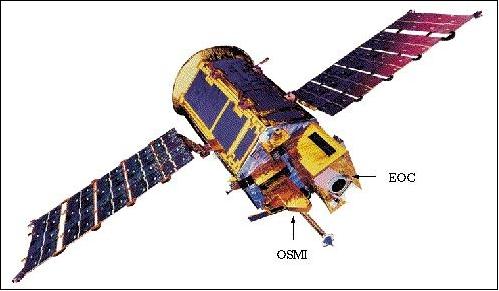
There were three main instrumentation groups onboard KOMPSAT-1.
- The Electro-optical Camera (EOC) carried out high-resolution imaging of the Korean peninsula, producing digital cartographic data.
- The Ocean Scanning Multispectral Imager (OSMI) was a wide-swath camera, producing low-resolution ocean images, tacking characteristics such as colour variation. This data was used to inform KARI scientists as to the regional marine biology as well as provide coastal support.
- KOMPSAT-1 also contained a space physics sensor, consisting of a High Energy Particle Detector (HEPD) and an Ionospheric Measurement Sensor (IMS).
HEPD was able to detect high-energy protons and electrons, giving information about the particle environment in LEO in order to quantify the effect on electronics. IMS contained an electron temperature sensor (ETS) and an electron density sensor (EDS), the latter of which was a modified Langmuir Probe used to monitor the variation in the nighttime ionosphere.
Performance Specifications
The EOC operated at high resolution, imaging at a scale of 1:25,000. This corresponded to being able to distinguish objects with a diameter of 6.6 m at nadir, with a swath width of 17 km by pushbroom scanning. EOC viewed over a spectral region of 510 - 730 nm.
OSMI was a whiskbroom-type imager, producing pictures across six spectral bands, ranging from 400 to 900 nm. KOMPSAT-1 had the capability to move each band centre by 2.6 nm. The spatial resolution was lower than that of the EOC, with a ground resolution of 1 km in a swath of 800 km.
EDMS consisted of three parts. The Proton and Electron Spectrometer (PES) could measure protons from 6.4 MeV to 38 MeV and electrons from 0.25 MeV to less than 2.0 MeV, both of which operated across three energy channels. A Linear Energy transfer Spectrometer (LET) and Total Dose Monitor (TDM) additionally quantified the integrated energy budget of high radiation bursts. IMS’s electron temperature sensor could measure electrons with energies ranging from 0 - 1 eV while the density sensor’s range was 10 - 106 e/cm3.
KOMPSAT-1 moved on a Sun-synchronous circular polar orbit, at an altitude of 685 km and an inclination of 98.13º. This corresponded to completing 14 and a half orbits per day, with a revisit time of 28 days.
Space and Hardware Components
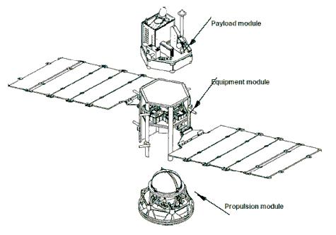
KOMPSAT-1 spacecraft was modelled off the National Aeronautics and Space Administration (NASA) TRW standardised bus. It contained three modules, including a core module housing power management, telemetry operations and data handling. One module was dedicated to instrumentation required for the science objective, including various imagers and space physics equipment. The final module contained a monopropellant hydrazine propulsion system, providing KOMPSAT-1 with on-orbit thrust.
Data was transmitted to and from the satellite to the ground station via Radio Frequency (RF) communication, with the downlink and uplink operated over S and X band frequencies respectively. KARI lost communication with KOMPSAT-1 in 2007, due to an expected malfunction preventing sufficient power generation. KOMPSAT-2 and KOMPSAT-3 were launched in 2006 and 2012, respectively.
KOMPSAT-1 (Korea Multi-Purpose Satellite-1) / Arirang-1
Overview
The KOMPSAT program was initiated in 1995 as a major space investment in Korea. Its objective is the development of a national space segment in Earth observation along with an efficient infrastructure and ground segment to provide valuable services to remote sensing users in various fields of applications.
The science objectives of KOMPSAT-1 are:
- To provide high-resolution imagery of the Korean Peninsula using EOC (Electro-Optical Camera)
- To collect wide-swath multispectral imagery of the ocean and coastal zones to support biological oceanography
- To provide information on the LEO particle environment and globally on the plasma distribution in the ion layer using SPS (Space Physics Sensor).
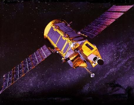
KOMPSAT-1 (Arirang-1) is a minisatellite, funded by the government of Korea and developed by KARI (Korea Aerospace Research Institute) in Taejon, along with seven Korean companies/institutes as well as by TRW of Redondo Beach, CA. The main objective of KOMPSAT-1 is to obtain imagery of the Earth's surface. 1) 2) 3)
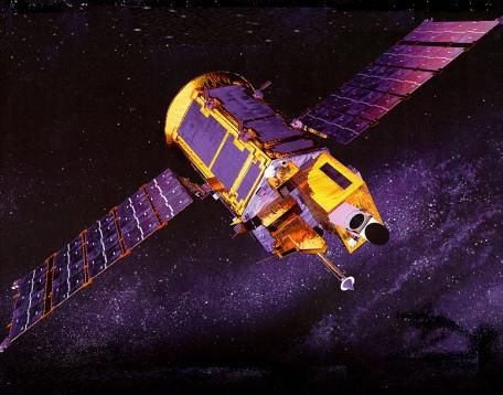
Spacecraft
The KOMPSAT-1 spacecraft is based on a TRW-developed standardized bus (of TOMS-EP heritage, including a MIL-STD-1555B communications bus) that can be easily modified to support a variety of mission requirements. A core (or equipment) module houses the housekeeping functions - power, telemetry and data handling, and attitude control - needed on all space missions. A payload module hosts mission-unique equipment, KOMPSAT's imaging instruments and space physics experiments. A third module, housing a monopropellant hydrazine propulsion system, provides on-orbit thrust and station-keeping.
The spacecraft size of KOMPSAT-1 is 1.33 m in diameter and 2.33 m in length. The platform uses a three-axis stabilized bus with a reaction control subsystem module, providing a 2-sigma pointing accuracy of 0.01º (roll), 0.18º (pitch) and 0.50º (yaw), and a pointing knowledge of 0.08º (roll and pitch) and 0.10º (yaw). The S/C mass is 510 kg (including 73 kg hydrazine), power = 630 W (500 W EOL), and the S/C design life is three years.

Launch
The KOMPSAT-1 satellite was launched on a Taurus booster (along with ACRIMSAT) from VAFB, CA on Dec. 20, 1999.
RF communication:
S-band, downlink data rates are at 1.5 Mbit/s (playback) or 2.048 kbit/s (real-time), and the uplink data rate is at 2 kbit/s. A second downlink in X-band provides data rates of 45 Mbit/s. The CCSDS protocol standards of CEOS are implemented for all communications. KOMPSAT-1 features a 1 Gbit onboard mass memory storage and an 8 Gbit solid-state recorder. As of 2004, KOMPSAT-1 data are also being acquired in Europe at DLR Neustrelitz (test acquisitions in preparation for KOMPSAT-2 data).
Orbit:
Sun-synchronous circular polar orbit, altitude = 685 km, inclination = 98.13º, period = 98.46 min, local equatorial crossing on ascending node at 10:50 hours, 14 17/28 orbits per day, revisit time = 28 days.
KOMPSAT has three onboard processors:
- OBC (On-Board Computer) for command, telemetry and data handling management,
- RDU (Remote Drive Unit) for attitude and orbit control management including propulsion subsystem,
- ECU (Electrical power system Control Unit) for electrical power and thermal control management.
These three onboard processors are interfaced through the MIL-STD-1553B data bus for basic communication and data handling functions between them as shown in Figure 4. 4)
The KGS (KOMPSAT Ground Segment) is located at Taejon, Korea, consisting of KMCS (KOMPSAT Mission Control Center) and KRPS (KOMPSAT Receiving and Processing System).
Mission Status
KARI lost contact with its spacecraft on Dec. 30, 2007 -- ending the operational life of the KOMPSAT-1/Arirang-1 mission. Initial reviews pointed toward a possible machinery malfunction or a misalignment that may have affected power generation. - In the first half of January 2008, KARI had made repeated but unsuccessful uplink efforts since contact was lost on December 30. As of Jan. 31, 2008, the KOMPSAT-1/Arirang-1 mission was officially retired. The satellite is programmed to use its own power for an orbital descent and re-entry. 5) 6) 7)
• The KOMPSAT-1 spacecraft and its optical payload provided an operational period of 8 years (5 years beyond the design life of 3 years). 8) 9)
• The SPS (Space Physics Sensor) instrument experienced a malfunction in 2001 and is no longer operational.
Sensor Complement
EOC (Electro-Optical Camera)
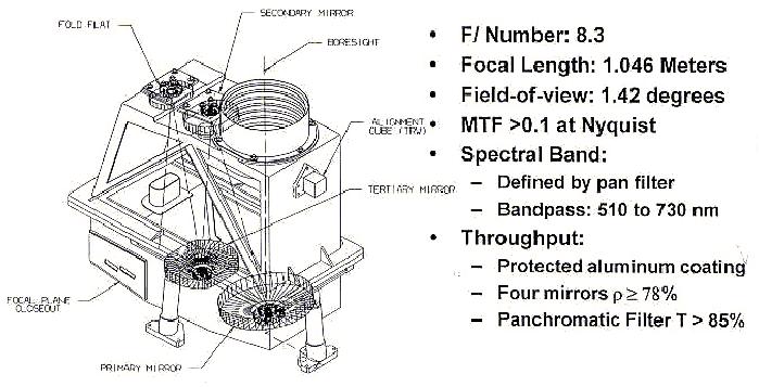
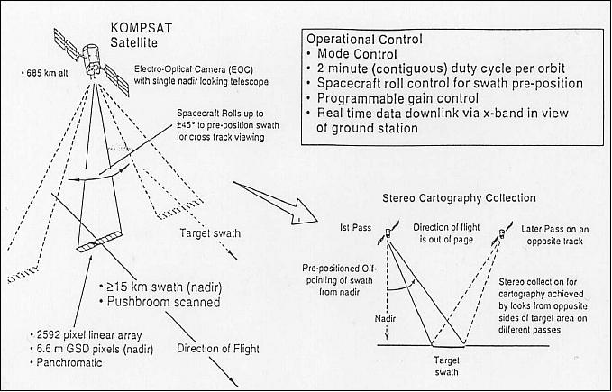
The objective is to obtain cartographic imagery of Korea (which may be extended to other regions of the globe) at a 1/25.000 scale. EOC collects panchromatic imagery (spectral region of 510 - 730 nm) with a ground sample distance (GSD) at nadir of 6.6 m and a swath width of 17 km by pushbroom scanning. The S/C features a cross-track pointing capability (body pointing) of up to ±45º, thereby extending the field of regard for imagery collection.
Some instrument parameters:
MTF >10% at Nyquist frequency, SNR >50 over the entire FOV, FPA has a CCD line array of 2592 pixels, data quantization of 8 bits, total instrument mass is 35 kg, power = 46 W, the source data rate is equal to or less than 25 Mbit/s.
- Calibration: use of a built-in dark calibration function. In addition, ground reference targets of known brightness can be used for white calibration. 10) 11)
OSMI (Ocean Scanning Multispectral Imager)
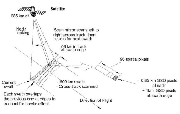
The wide-swath instrument is also referred to as LRC (Low-Resolution Camera). The objective is global ocean colour monitoring for the study of biological oceanography. OSMI is a whiskbroom-type imager generating imagery in up to six spectral bands (in the region of 400 - 900 nm) with a capability for bandwidth and band centre selection on command. The centre of each band can be varied within steps of 2.6 nm, and bandwidth ranges from 5.2 nm (min) to 166.4 nm (max) can be assigned.
The ground resolution is 1 km in a swath of 800 km (0.85 km at nadir and about 1 km at the edge of the swath). The scanner assembly features a line array of 96 detectors (Si), positioned in the along-track direction, thus providing an instantaneous parallel ground coverage of 96 km in one cross-track scan with the whiskbroom configuration. This wide along-track coverage permits sufficient integration time for all cells in each scan sweep of about 15 seconds. Naturally, there is some overlap for successive scans.
The ensuing collecting optics perform the spectral separation of the radiation received. The bands B0 through B4 provide ocean colour data, and the other bands provide information for atmospheric (aerosol) corrections.
Some instrument parameters:
MTF is about 20% at Nyquist frequency, SNR is between 350 and 450 over the entire FOV, data quantization = 10 bits, instrument mass = 15 kg, power = 30 W, the source data rate is 600 kbit/s. The duty cycle for image collection is 20%.
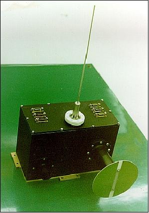
- Calibration: A solar calibration is performed with an onboard spectralon once per orbit (note: a spectralon is a kind of optical diffuser which can be used as a Lambertian source). Dark calibration is performed before and after each imaging period. 12) 13) 14) 15) 16) 17)
Spectral bands | B0 | B1 | B2 | B3 | B4 | B5 | BX | B6 |
Centre wavelength (nm) | 412 | 443 | 490 | 510 | 555 | 670 | 765 | 865 |
Nominal bandwidth (nm) | 20 | 20 | 20 | 20 | 20 | 20 | 40 | 40 |
Low band edge (nm) | 401.64 | 432.88 | 479.76 | 500.59 | 544.86 | 659.43 | 745.36 | 846.92 |
High band edge (nm) | 422.47 | 453.72 | 500.59 | 521.42 | 565.69 | 680.26 | 787.03 | 888.58 |
Band selection parameters | - Maximum selectable band numbers: 6 band |
Gain and offset control parameters | - Gain control parameter: 8 step |
On-orbit calibration by ground command | - Solar calibration on the north pole per orbit |
LRC SOH data for mission operation | - Temperatures and powers status |
Image data storage capability | - 4 Gbit at BOL (Beginning Of Life) allocated |
SPS (Space Physics Sensor)
The SPS package consists of two instruments:
- HEPD (High Energy Particle Detector)
- IMS (Ionosphere Measurement Sensor).
The objective of HEPD is to characterize the low-altitude high-energy particle environment and to study the effects of the radiation environment on microelectronics. The objective of IMS is to measure the in-situ densities and temperature of electrons in the ionosphere. 18)
• HEPD in turn consists of the following instruments: PES (Proton and Electron Spectrometer), LET (Linear Energy Transfer Spectrometer), TDM (Total Dose Monitor), and SEM (Single Event Monitor).
- PES identifies the particle types detected and measures their energy in seven channels. Objective: distribution of energetic electrons and protons in the radiation belts.
- LET measures particle populations, providing information of radiation effects on electronic components (comparison with TDM and SEM data).
- TDM measures with RADFET dosimeters the long-term ionizing dose of radiation (in SiO2) accumulated at SPS. The threshold voltage provides information with respect to dose accumulation.
- The objective of SEM is to test exposed non-space qualified static RAM components in the radiation environment of KOMPSAT-1 for future space missions. The experiment uses four static RAM chips (4 Mbit), connected to appropriate circuitry, to measure SEU (Single Event Upset) characteristics.
• The IMS instrument contains an electron temperature sensor (ETS) and an electron density sensor (EDS), measuring temperature and density distributions of electrons (ionospheric plasma). EDS is a modification of a Langmuir Probe. The measurement range for ETS is 0 - 1 eV, and for EDS the range is 10 - 106 e/cm3.
Channel | Particle | Energy Range (MeV) |
pE1 | Proton | 30-38 |
pE2 | Proton | 15-30 |
pE3 | Proton | 6.4-15 |
eE1 | Electron | 2.0 < |
eE2 | Electron | 0.72-2.0 |
eE3 | Electron | 0.25-0.7 |
AA | Alpha particle | 15-60 |
References
1) Information provided by H. Paik and G. H. Choi of KARI
2) H. Y. Paik, KOMPSAT-1 Payloads,” http://sol.oc.ntu.edu.tw/omisar/wksp.mtg/ocare98/Kompsat/KOMPSAT1.htm
3) B.-S. Kim, H. S. Kim, G. W. Morgenthaler, “The KOMPSAT Program to Provide Various Applications in the Field of Earth Observation covering Land, Sea, and Coastal Zones,” Proceedings of the 56th IAC 2005, Fukuoda, Japan, Oct. 17-21, 2005, IAC-05-B1.1.06
4) M.-J. Baek, J.-I. Lee, E.-S. Sim, H.-J. Kim, J.-J. Lee, “On-Board Management of Multiple Processor Spacecraft System,” Proceedings of the IEEE Aerospace Conference, Big Sky, MT, Mar. 9-16, 2002
5) “S. Korea decides to terminate satellite: space agency,” Spacedaily, Jan. 13. 2008, URL: http://www.spacemart.com/reports/SKorea_decides_to_terminate_satellite_space_agency_999.html
6) http://www.spacedaily.com/reports/South_Korea_Confirms_Contact_With_Satellite_Lost_999.html
7) Ok-Chul Jung, Dae-Won Chung, Sun-Ju Park, Dae-Hwan Hyun, Yong-Sik Chun, “Advanced Concept and Design of the Multi-satellite Operations System,” Proceedings of the SpaceOps 2010 Conference, Huntsville, ALA, USA, April 25-30, 2010, paper: AIAA 2010-2333
8) Information provided by Hae-Dong Kim of KARI, Daejeon, Korea
9) Hyo-Suk Lim, “Applications of KOMPSAT Data and Space Program of Korea,” URL: http://www.aprsaf.org/data/vietnam_ws/vws_14.pdf
10) H. Paik, G. Choi, H. Youn, S. Lee, S. Woo, H. Shim, K. Oh, Y. Cho, S. Yong, S. Lee, H. Heo, “The KOMPSAT-1 payloads overview,” Proceedings International Symposium on Remote Sensing, Kwangju, Korea, Sept. 16-18, 1998, pp. 301-306,
11) Kim Bang, Woosug Cho, “KOMPSAT-EOC Sensor Model Analysis,” URL: http://www.fig.net/pub/proceedings/korea/full-papers/pdf/session4/bang-cho.pdf
12) Note: Preference is given to a whiskbroom imager (the older imaging technology) because the optics for pushbroom operation must always cover FOV (the total field of view) while the optics for whiskbroom operation deal with IFOV (instantaneous field of view) which is much smaller than FOV. Hence, there are less distortions at the swath edge.
13) Y. M. Cho, S. S. Yong, et. al., “Ocean Scanning Multispectral Imager (OSMI),” Proceedings Fifth International Conference on Remote Sensing for Marine and Coastal Environments, San Diego, CA, Oct. 5-7, 1998
14) Y. M. Cho, “Ocean Scanning Multispectral Imager (OSMI), Post-launch Radiometric Responsivity Analysis,” Proceedings of IEEE/IGARSS 2000, Honolulu, HI, July 24-28, 2000
15) B. Sohn, D. Kim, S. Yoo, Y. Kim, “Calibrating OSMI sensor with in-situ measurements,” in Proc. Int. Symposium on Remote Sensing, Kyongju, Korea, November 1-3, 2000, pp. 456-460
16) B. A. Franz, Y. Kim, “A comparative study and intercalibration between OSMI and SeaWiFS,” AGU 2001 Fall Meeting, San Francisco, CA, Dec. 10-14, 2001
17) Yu-Hwan Ahn, “Status of KOMPSAT-1 OSMI,” 10th IOCCG Meeting, 19-21 January 2005, Isla de Margartia, Venezuela, URL: http://www.ioccg.org/sensors/osmi/AHN.pdf
18) https://web.archive.org/web/20151024025842/http://satrec.kaist.ac.kr/english/res_spslrc.html
The information compiled and edited in this article was provided by Herbert J. Kramer from his documentation of: ”Observation of the Earth and Its Environment: Survey of Missions and Sensors” (Springer Verlag) as well as many other sources after the publication of the 4th edition in 2002. - Comments and corrections to this article are always welcome for further updates (eoportal@symbios.space).