KOMPSAT-2 (Korea Multi-Purpose Satellite-2) / Arirang-2
EO
High resolution optical imagers
Land
Multi-purpose imagery (land)
Launched in July 2006, KOMPSAT-2 (Korea Multi-Purpose Satellite), also known as Arirang-2, was developed and is operated by KARI (Korea Aerospace Research Institute) as the successor to KOMPSAT-1. It aims to provide surveillance capabilities for large-scale disasters by collecting high-resolution imagery with GIS (Geographic Information Systems) applications.
Quick facts
Overview
| Mission type | EO |
| Agency | KARI, E-LOP, ASTRIUM |
| Mission status | Operational (extended) |
| Launch date | 27 Jul 2006 |
| Measurement domain | Land |
| Measurement category | Multi-purpose imagery (land), Vegetation, Landscape topography |
| Measurement detailed | Land surface imagery, Vegetation type, Land surface topography |
| Instruments | MSC |
| Instrument type | High resolution optical imagers |
| CEOS EO Handbook | See KOMPSAT-2 (Korea Multi-Purpose Satellite-2) / Arirang-2 summary |
Related Resources

Summary
Mission Capabilities
KOMPSAT-2 carries a single instrument, MSC (Multispectral Camera), a high-resolution optical imager.
MSC aims to capture high-resolution imagery with cartography and disaster monitoring applications, specifically in landscape topography, multipurpose land imagery and vegetation observations.
Performance Specifications
MSC utilises a pushbroom scanning method and operates across five bands, one panchromatic band, and four multispectral (MS) bands. Its panchromatic band has a spectral range of 500-900 nm, with a GSD (Ground Sample Distance) of 1 m. Its MS bands have spectral ranges of 450-520 nm, 520-600 nm, 630-690 nm and 760-900 nm, with a GSD of 4 m across all MS bands. MSC has a swath width of 15 km at nadir across all bands and a field of view (FOV) of ±0.62°.
KOMPSAT-2 operates in an identical orbit to KOMPSAT-1, 180° out of phase, in a sun-synchronous circular orbit of altitude 685 km, inclination 98.13° and period 98.46 minutes. It has an LTAN (Local Time on Ascending Node) at 1050 hours, and a repeat cycle of 28 days.
Space and Hardware Components
The bus used for KOMPSAT-2 is primarily based on the design of its predecessor, KOMPSAT-1, allowing parallel integration of the payload, equipment, and propulsion modules.
The bus houses seven modules:
- SMS (Structure and Mechanisms Subsystem),
- TCS (Thermal Control Subsystem),
- AOCS (Attitude and Orbit Control Subsystem),
- TC&R (Telemetry Command and Ranging) subsystem,
- EPS (Electrical Power Subsystem),
- PS (Propulsion Subsystem),
- FSW (Flight Software) element.
The spacecraft has a launch mass of 800 kg, with deployed dimensions of 1.85 m x 2.6 m x 6.8 m. The bus houses an onboard storage capacity of 96 Gbit.
TT&C (Tracking, Telemetry and Command) data is transmitted in S-band, while data is downlinked in X-band, with a downlink data rate of 320 Mbit/s and S-band data rates of 2 kbit/s uplink and 1.5 Mbit/s downlink.
KOMPSAT-2 (Korea Multi-Purpose Satellite-2) / Arirang-2
Spacecraft Launch Mission Status Sensor Complement Ground Segment References
KOMPSAT-2 (also referred to as Arirang-2 by South Korea) was developed by KARI (Korea Aerospace Research Institute) to continue the observation program of the KOMPSAT-1 mission.
The main mission objectives of the KOMPSAT-2 are to provide a surveillance capability for large-scale disasters by acquiring high-resolution imagery for GIS (Geographic Information Systems) applications. 1) 2) 3) 4) 5) 6)
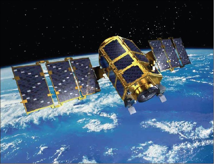
Spacecraft
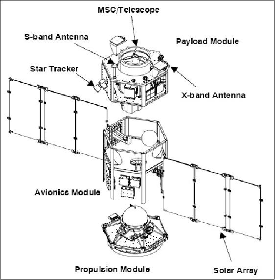
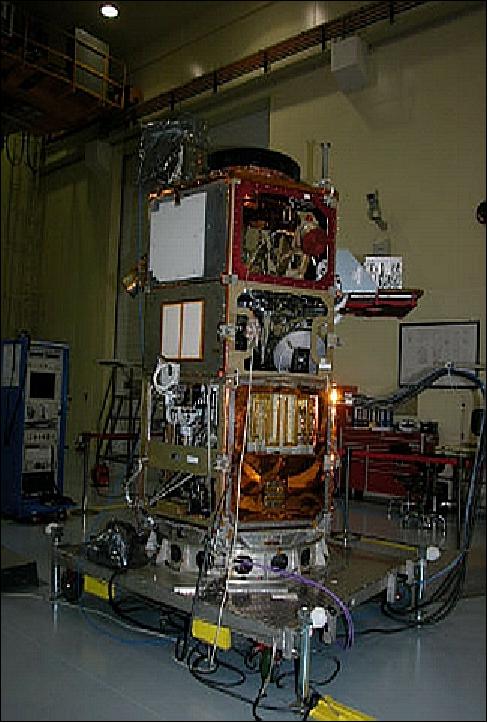
The spacecraft design is based on the KOMPSAT-1 heritage making extensive use of existing hardware, software, tools, and facilities; it allows parallel integration of the payload, equipment, and propulsion modules.
The KOMPSAT-2 bus structure consists of the following modules:
- SMS (Structure and Mechanisms Subsystem),
- TCS (Thermal ConTrol Subsystem),
- AOCS (Attitude and Orbit Control Subsystem),
- TC&R (Telemetry Command and Ranging) subsystem,
- EPS (Electrical Power Subsystem),
- PS (Propulsion Subsystem),
- FSW (Flight Software) element.
The AOCS provides three-axis stabilization (3-axis control with zero momentum bias system) with high accuracy for roll, pitch and yaw pointing. Star trackers, gyro reference assemblies, three-axis magnetometers, magnetic torquers and reaction wheels are used for attitude sensing and control.
The pointing accuracy is < 0.025º in roll and pitch, and 0.08º in yaw. The pointing knowledge is 0.020º in roll and pitch, and 0.045º in yaw. The spacecraft platform offers a cross-track body-pointing capability through roll maneuvers (up to ±45º). The propulsion subsystem makes use of re-used components (hydrazine monopropellant thrusters with blowdown pressure-feed system, 73 kg propellant). 7) 8) 9)
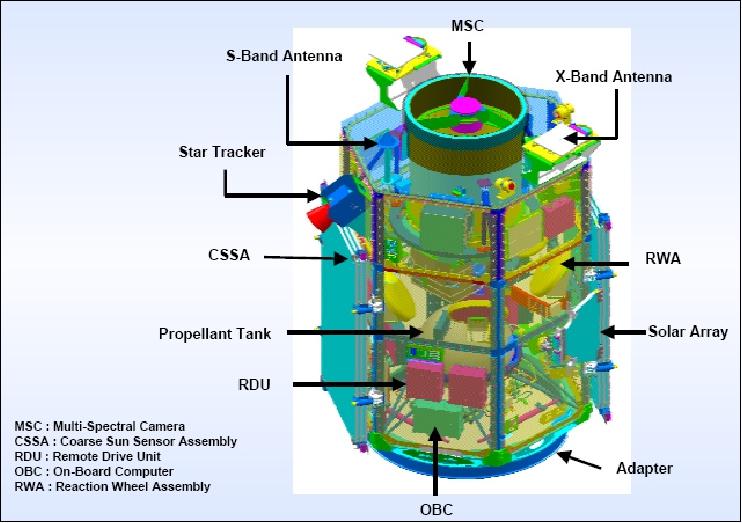
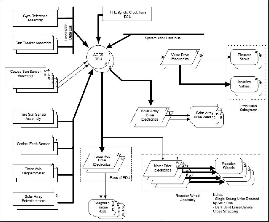
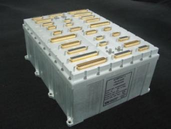
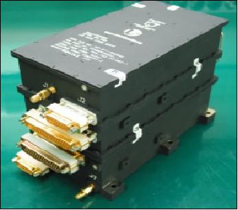
A MIL-STD-1553B data bus interfaces most of the spacecraft bus and payload to the onboard computer (monitoring and control). A GPS receiver (Topstar 3000 of Alcatel) provides the onboard time, satellite position and velocity. 10) 11)
The spacecraft mass is 800 kg (including propellant), the S/C size is hexagonal: 1.85 m diameter x 2.6 m in height (6.8 m length in deployed configuration), the power is 955 W (EOL) provided by two solar arrays (GaAs cell technology). A super NiCd battery has a capacity of 30 Ah for eclipse phase support. The S/C design life is three years. EADS Astrium has been selected by KARI to support the platform development and manufacture of KOMPSAT-2.
Launch
Launch:
The KOMPSAT-2 spacecraft was launched on July 28, 2006, with a Rockot-KM launch vehicle of Eurockot Launch Services from the Plesetsk Cosmodrome, Russia. 12)
Orbit:
Sun-synchronous circular orbit, altitude = 685 km, inclination = 98.13º, period = 98.46 min, the mean local time of the ascending node is at 10:50 hours. Repeat cycle = 28 days. The KOMPSAT-2 orbit is identical to that of KOMPSAT-1 but with a different phase (180º apart).
RF communications:
Onboard storage capacity of 96 Gbit (BOL) and 64 Gbit (EOL) for image data. S-band (TT&C) and X-band (payload data at 8.205 GHz downlink frequency) communications are provided for all data transmission to the ground (real-time and playback), and the downlink data rate is 320 Mbit/s (QPSK modulation). Encryption of image data. The CCSDS communication protocols are implemented.
The S-band data rates are 2 kbit/s uplink and 1.5 Mbit/s downlink.
Mission Status
• January 2019: The KOMPSAT-2/Arirang-2 mission is fully operational in its 13th year of service. SIIS (SI Imaging Services), a subsidiary of SI (Satrec Initiative), is the exclusive worldwide marketing and sales representative of the KOMPSAT series KOMPSAT-2, KOMPSAT-3, KOMPSAT-3A and KOMPSAT-5. 13)
• The KOMPSAT-2/Arirang-2 mission is operational in January 2017 in its 11th year on orbit. 14)
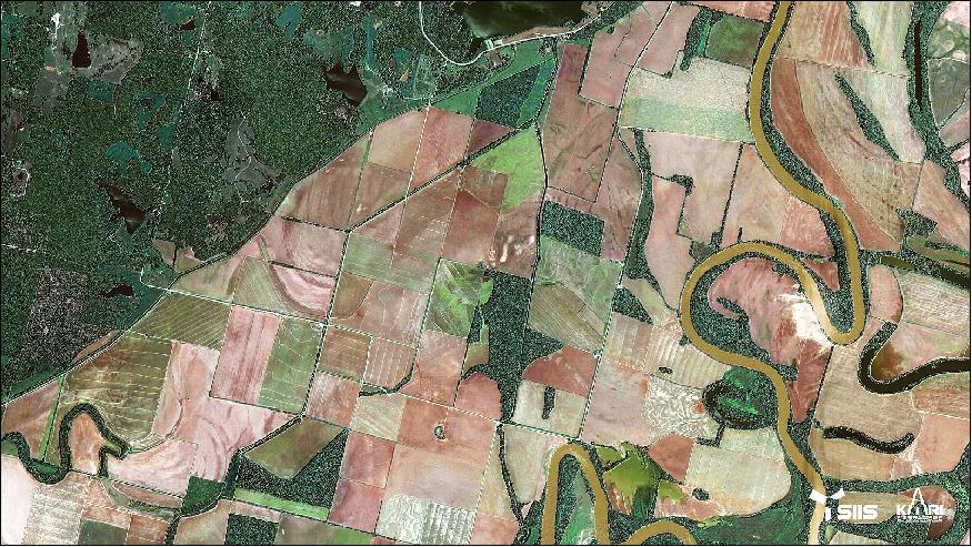
• The KOMPSAT-2 mission is operational in March 2016 and will be continued to the end of its lifetime for experimentation. There is still more than 40 kg of fuel onboard (initial value 72.5 kg), enough power margin, and no outstanding anomaly. 15)
• In October 2015, the MSIP (Ministry of Science, ICT and Future Planning) and KARI made plans about the future of the KOMPSAT-2 mission which is on orbit for more than 9 years. It was decided not to extend the KOMPSAT-2 mission any further for systematic observation services, but instead use it for research purposes until the end of its life cycle.
Although KOMPSAT-2 was originally designed to have a life cycle of 3 years, this was extended three times (by two years each time, for a total of 6 years) by applying highly reliable satellite technology. As such, KOMPSAT-2 has successfully carried out its mission of obtaining images of the Korean Peninsula and other major areas of the world over a period of nine years. 16)
- From now on, KOMPSAT-2 will be used in next-generation satellite technology research without any further extension of its mission until the end of its life cycle, as its operation systems - such as its payload module, sensor, and earth station operation system (command transmission and satellite condition analysis) - are aged.
- KOMPSAT-2 was a milestone, since the basis for the development of the Korean model was established and the foundation of space industrialization was laid by investing KRW (Korean Won) 263.3 billion from 1999 to 2006 to secure the design, fabrication, assembly, and testing capability led by Korean technology based on the experience in the joint international development of KOMPSAT-1.
- The satellite was designed and fabricated jointly by KARI and 29 Korean companies, while the payload was jointly developed with ELOP in Israel (20 technical professionals dispatched during 4 years).
- The development of KOMPSAT-2 resulted in 91.5% self-sufficiency (54 out of 59 key technologies secured) in terms of satellite design and 65.2% self-sufficiency (30 out of 46 key technologies secured) in satellite parts fabrication, thereby establishing the basis for Korean self-sufficiency in the space technology sector.
- By developing KOMPSAT-2, Korea became the 7th country in the world to own a 1m class high-resolution satellite, and successfully established a strategic milestone for cooperation and the sharing of satellite information.
- Over the past 9 years, KOMPSAT-2 has orbited the Earth some 46,800 times and communicated with the Earth around 26,000 times. It has acquired 75,400 images of Korea and 2,448,300 images of the rest of the world, thus playing a key role in building up the nation's image assets.
- Until the mission end, KOMPSAT-2 will continue to operate alongside the other Korean satellites, KOMPSAT-3 (launched in May 2012), KOMPSAT-5 (launched in August 2013) and KOMPSAT-3A (launched in March 2015), all of which are currently in operation, in an effort to fulfil the demand for national satellite utilization. The MSIP plans are to support key technologies for application in the private sector and to promote the relevant industries.
• The KOMPSAT-2 mission is operational in 2015.
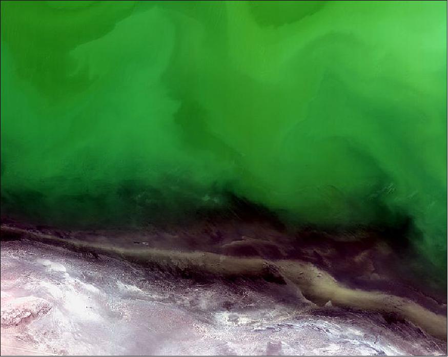
Figure 9 was released by ESA on January 16, 2015, showing a portion of the shoreline of the Caspian Sea. The Caspian Sea is the largest landlocked water body in the world, with a surface area of 371 000 km2. It is bounded to the northeast by Kazakhstan, to the northwest by Russia, to the west by Azerbaijan, to the south by Iran, and to the southeast by Turkmenistan. The shallow northern section of the Sea has an average depth of about 5–6 m, although it fluctuates depending on variations in river flow and wind-driven currents. The water appears green in this image, indicating an algal bloom. 17)
- Caused by heightened levels of phosphorus – found in fertilizers, detergents and unfiltered sewage – finding its way into the water, these blooms deplete the amount of oxygen in the water. This causes a reduction in aquatic life and poses a threat to rich fisheries: the Caspian Sea is an important site for sturgeon, which yield roe (eggs) that are processed into caviar.
- The mineral-rich land of Kazakhstan's Mangistau region is visible at the bottom of the image. With large fossil fuel reserves and an abundant supply of other minerals and metals, Mangistau is sometimes called the ‘treasure peninsula' of Kazakhstan.
• Nov. 28, 2014: Peru's Quelccaya glacier, located in the Cordillera Oriental of the Peruvian Andes (Figure 10), has been shrinking due to rising temperatures in the region, losing over 20% of its area since the 1970s. Downstream communities rely on this water source for drinking and electricity in this dry region, but some estimates show that the ice cap will vanish in a matter of decades, draining the water supply for millions of people. 18)
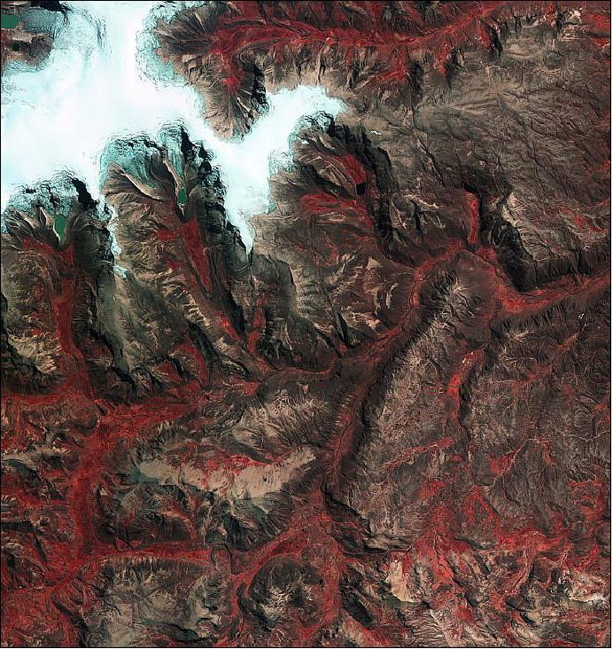
Legend to Figure 10:
In the far upper-left corner of the image, one can see the Qori Kalis Glacier, the ice cap's main outlet. This glacier is retreating – and this retreat has accelerated in recent years – losing about 50% of its total length since the 1960s. As a result of the glacier's melting, a lake began to form in the late 1980s and has grown over the years. -Other smaller lakes have also formed around the ice cap. Meltwater lakes are generally lighter in colour through the presence of fine particles produced by the grinding of the ice over bedrock – called ‘rock flour'. When this ‘flour' turns the water white or cloudy, it is referred to as ‘glacial milk'. The false colour of this image makes vegetation appear bright red, and we can clearly see how vegetation grows mainly in the valleys and along the paths of water runoff.
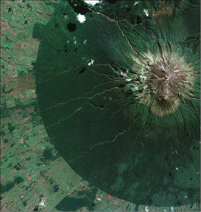
• October 31, 2014: Egmont National Park on New Zealand's North Island is pictured in this satellite image of Figure 11. National parks protect forested areas from human activities that cause land degradation and deforestation. The boundary between protected and non-protected areas is often very clear in satellite images – as we see here between the green, densely forested area and the surrounding agricultural landscape. 19)
The land here was first formally protected in 1881, within a 9.6 km radius of the mountain summit. With high rainfall and a mild coastal climate, the park is home to lush rainforests, with some plants unique to the park. Halfway up the mountain slopes, the forest is sometimes called the ‘Goblin Forest' for its gnarled trees and thick moss.
The mountain at the centre of the national park has two names: Mount Egmont and Mount Taranaki. Taranaki is the original name given by the indigenous Māori people, while the name Egmont was given by British explorer James Cook after John Perceval, 2nd Earl of Egmont in 1770. Many places in New Zealand have official dual names or, as in this case, alternate names in the original Māori and English (following colonization by the British).
The mountain is considered an active volcano, although it has been dormant for over 150 years.
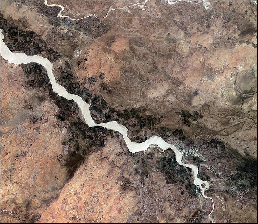
• October 10, 2014: The image of Figure 12, shows an area in the southern Darfur region of Sudan (Africa), just south of the city of Nyala. The Wadi Nyala flows diagonally across the image, surrounded by agricultural plots. To the north, we can see the straight line of the railway. The city of Nyala to the northwest (not pictured) was formerly a nomadic camp, but experienced a boom in commercial activity with the arrival of the railway in the 1950s. The population further increased as people moved to the town during times of drought and conflict. 20)
Satellite images can assist in identifying water resources and aid the sustainable growth of urban areas. During conflict, they can also be used to find suitable locations for refugee camps by identifying where water and other resources are available, and suitable terrain. In the upper-left section of Figure 12, one can see thousands of small structures of the Kalma camp, housing tens of thousands of internally displaced people who have fled the Darfur conflict.
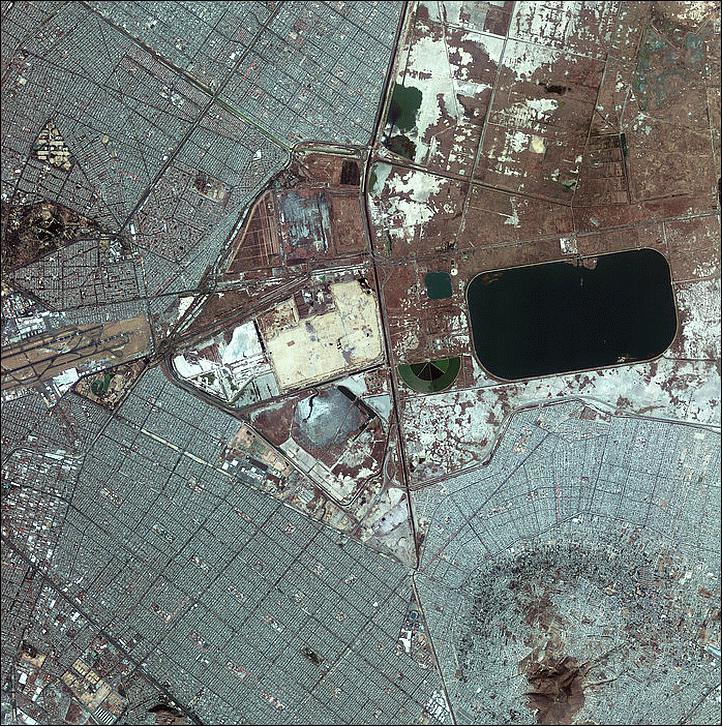
• July 18, 2014: The KOMPSAT-2 image of Figure 13, released on July 18, 2014, in ESA's 'image of the week series', shows the eastern part of Mexico City. The area pictured lies within central Mexico's highlands plateau called the Valley of Mexico. This valley (minimum altitude of 2000 m) was originally covered by the waters of Lake Texcoco, but over the centuries the water has been drained. The area that has not been built up is today used for hydraulic management and is made up of reservoirs and ponds such as the large, dark Nabor Carrillo lake pictured here. 21) 22)
The area receives more than 100 000 migratory birds each year that travel through the Central Migratory Flyway, and is a key resting, feeding and breeding ground for several species of shorebirds.
In contrast to the open space of the former Lake Texcoco, Mexico City is a densely populated metropolitan area (left and bottom). One can in Figure 13 see the runways of the international airport on the far left. South of the airport is the Alameda Oriente recreational park with its somewhat spiral artificial lake. North of the airport, El bosque de San Juan de Aragón is another park and an important green area.
City parks play a large role in the city's effort to alleviate air pollution. In the early 1990s, pollution was believed to cause hundreds of deaths each year. Air quality has improved in recent decades through a series of government efforts to cut emissions.
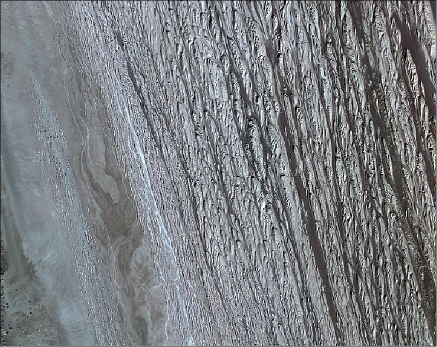
• June 19, 2014: The KOMPSAT-2 image of Figure 14, released on June 19, 2014, in ESA's 'image of the week series', shows southeast Iran's Dasht-e Lut salt desert. The desert is often called the ‘hottest place on Earth' as satellites measured record surface temperatures there for several years. The highest land surface temperature ever recorded was in the Lut Desert in 2005 at 70.7ºC, as measured by NASA's Aqua satellite. 23)
The area pictured is surrounded by salt flats, visible on the left side of the image. The ridges dominating the image extend about 125 km.
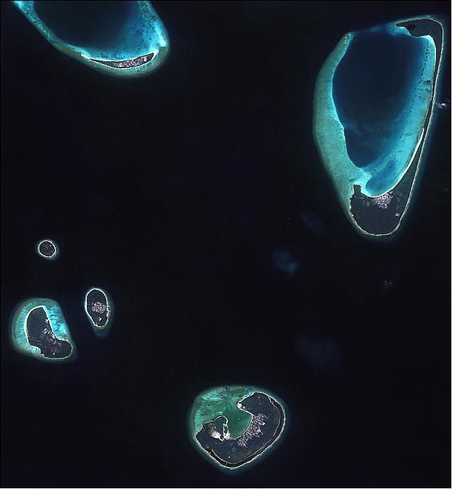
• June 5, 2014: The image from the Kompsat-2 satellite (Figure 15), acquired on January 9, 2011, shows the islands of the Haa Alif Atoll in the northern Maldive archipelago in the Indian Ocean. The Haa Alif Atoll contains 43 islands, 14 of which are inhabited and classified as 'island-class' constituencies. The Maldives are a member of the Alliance of Small Island States, they are one of the world's most vulnerable nations to the effects of climate change. 24)
As 2014 is the UN-designated International Year of Small Island Developing States, this year's theme focuses on the effects of climate change on small islands. Small islands and coastal areas are under threat from rising sea levels. An increase in global temperatures has accelerated the melting of glaciers and ice sheets. This influx of water together with the thermal expansion is causing the global sea level to rise by about 3 mm a year.
‘Raise your voice, not the sea level' is the theme for today's World Environment Day.
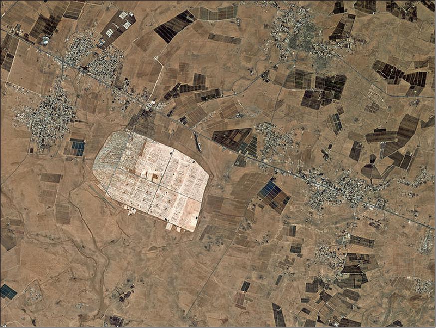
• May 2014: The KOMPSAT-2 image of Figure 16 shows an area 13 km east of the city of Mafraq in northern Jordan. Sitting geologically between the Syrian Desert and the volcanic Hauran plateau, the area experiences a desert climate. The light-coloured area in the image is the Zaatari Refugee Camp, measuring some 3 km across. Located just over 10 km from the border with Syria, the camp is currently home to over 100 000 people displaced by the conflict in the neighbouring country. The image is featured in the ESA "Earth from Space video program" and was released on May 23, 2014. 25)
• The KOMPSAT-2 spacecraft and its payload are operating nominally in 2014 (in its 8th year on orbit). Initially, the KOMPSAT-2 mission was planned to last for 3 years, but the operational life was extended already 3 times, as technical inspection proved it had no issues.
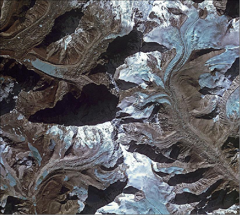
Legend to Figure 17:
The image, featured in the ESA's Earth from Space video program', was released on March 14, 2014. It shows an area of the Himalayan mountain range in northeastern Nepal, about 8 km south of Mount Everest (not pictured). The range is also home to thousands of glaciers, including the Imja glacier in the upper-central part of this image. Studies have shown an increase in the rate of glacial retreat for Imja and many other glaciers in the region – and in the world. 26)
• In June and July 2013, the KOMPSAT-2 Data Processing and Calibration/Validation Team of KARI performed cross-calibrations of the KOMPSAT-2 MSC (Multi Spectral Camera) using satellite imagery taken by the EO-1/Hyperion instrument of NASA. In this study, the DN (Digital Number) value from each band of the EO-1 Hyperion sensor, representing the spectral radiance at wavelength, was converted by applying the Relative Response Function of MSC to the interpolated radiance from EO-1. 27)
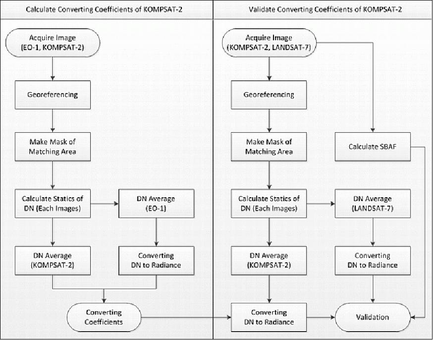
This study was conducted in the following order as shown in Figure 18:
- obtaining images;
- geometric correction;
- setting overlapping areas;
- calculating the mean DN of areas and a radiance conversion factor of DN.
The DN to radiance conversion factor of KOMPSAT-2 was calculated with the following formula, using the radiance converted from DN of KOMPSAT-2 and EO-1. The calculated factor was verified by applying SBAF to the radiance values measured with Landsat-7.
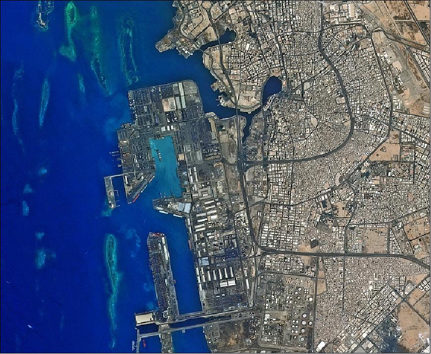
Legend to Figure 19:
The city of Jeddah's seaport on Saudi Arabia's western coast is pictured in this image from the KOMPSAT-2 satellite, released on Feb. 7, 2014, on ESA's Earth from Space video program. The second largest city in the country, Jeddah has a population of over five million people. The city is a gateway to Islam's holiest city of Mecca, which lies about 60 km to the east, as well as to the holy city of Medina, about 320 km north. Jeddah is also an important commercial hub, with its port located in the middle of an important shipping route between east and west. The Red Sea's coral reefs are visible off the coast. In fact, this is one of the few places along this coastline with a gap in the reef, enabling large vessels to approach the coast.
• KOMPSAT-2 is operational in 2013 (7th year on orbit) - and is expected to continue operations into the year 2014 (Ref. 31).
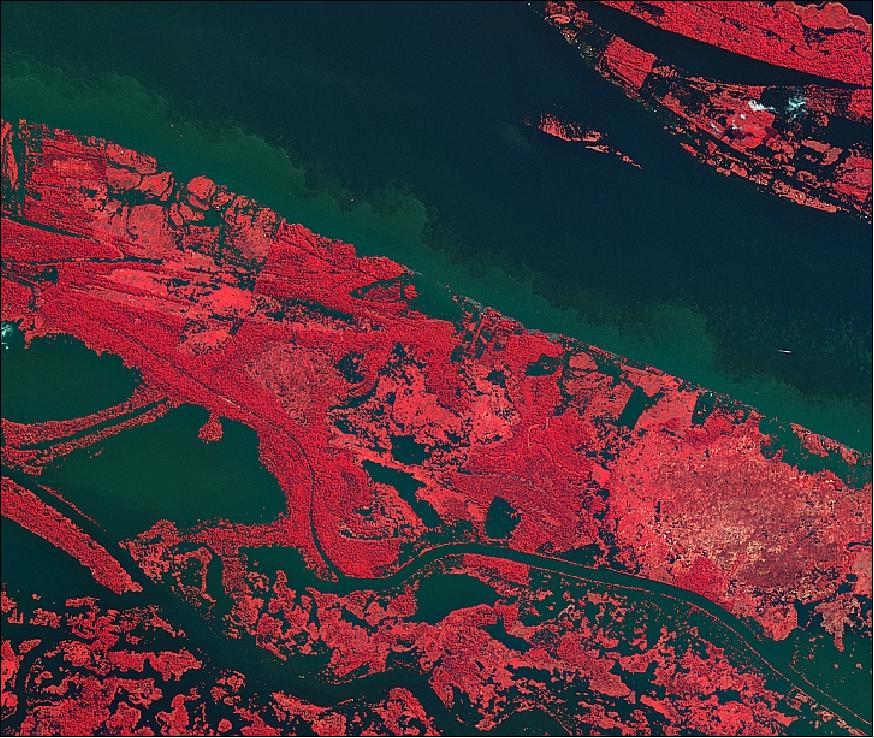
Legend to Figure 20:
This KOMPSAT-2 image, featured on ESA's Earth from Space video program, shows the Amazon River in the heart of northern Brazil's rainforest. The false colour makes land vegetation appear pink, while water appears green and dark blue. In the upper-right corner, we can see some sparse clouds. The shades of pink vary – the bolder colour represents thick vegetation with lighter pink showing where trees were possibly cut down. In fact, in the upper-left portion of the image, there's a clear line between the two shades, showing where vegetation was cut. The white dots show man-made structures. With their unique view from space, Earth observation satellites have been instrumental in highlighting the vulnerability of the rainforests by documenting the scale of deforestation. 29)
About 70 km west of the area pictured is the city of Manaus – the capital of Amazonas state.
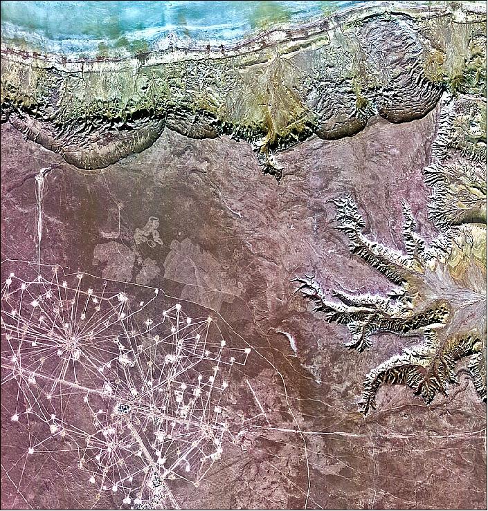
Legend to Figure 21: This KOMPSAT-2 image was acquired on 24 November 2012 over southwestern Kazakhstan's Mangistau region east of the Caspian Sea. Along the top of the image we can see water and wetlands, with eroded areas at the top and on the right. The majority of the image is dominated by flatland covered with low-lying vegetation. The bright web of roads in the lower left section of the image is the Karakuduk oil field. The white squares in this ‘web' indicate where wells are located. One can also see buildings and other structures related to oil production. Kazakhstan – and in particular, the Mangistau oblast – has large fossil fuel reserves and an abundant supply of other minerals and metals. Because of this, Mangistau is sometimes called the ‘treasure peninsula' of Kazakhstan.
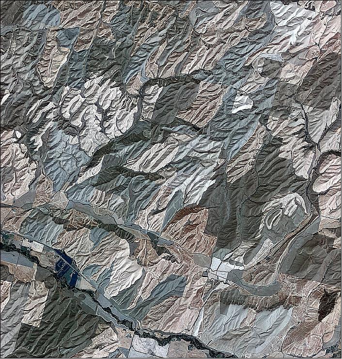
Legend to Figure 22:
The image was acquired over Washington state, the south and west areas of the image are in Walla Walla county, while the central-eastern-upper area is Columbia County. The area pictured is part of the Palouse region – an agricultural zone that mainly produces wheat and legumes. The rolling, picturesque landscape has sometimes been compared to Italy's Tuscany. Touchet River, known for its trout fishing, can be seen in the lower left. The diagonal line running next to the river is a road that connects the town of Prescott to the west to Waitsburg to the east. 30)
• In November 2012, KARI selected SI (Satrec Initiative) of Daejeon, Korea as the 'worldwide exclusive representative' for KOMPSAT imagery sales. This applies to the imagery of KOMPSAT-2, -3 and -5 missions. KARI has chosen Satrec Initiative for its ability to develop international customers and data distribution networks, as well as its long experience in the space industry. Satrec Initiative will deliver high-quality image data to worldwide customers through collaboration with existing satellite operators, and in addition to that, building its own KOMPSAT data distribution network. 31)
• The KOMPSAT-2 spacecraft and its payload are operating nominally in 2012. The spacecraft is well past its design life of 3 years. 32)
Note: The follow-on KOMPSAT-3 (Arirang-3) mission was launched on May 17, 2012, from TNSC, Japan.
• The Namib Desert image of Figure 23, featured on the 'Earth from Space video program', was released by ESA on May 10, 2013, by ESA.
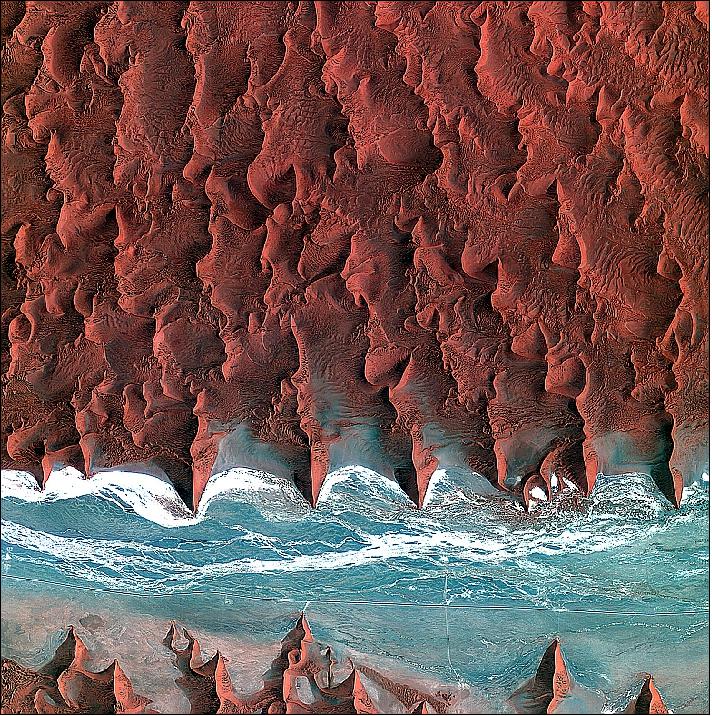
Legend to Figure 23:
The blue and white area is the dry river bed of the Tsauchab. Black dots of vegetation are concentrated close to the river's main route, while salt deposits appear bright white. Running through the river valley, a road connects Sossusvlei to the Sesriem settlement. At the road's 45th kilometre, seen at the lower-central part of the image, a white path shoots off and ends at a circular parking area at the base of a dune. This is Dune 45, a popular tourist stop on the way to and from Sossusvlei. In this image, there appears to be some shadow on the western side. From this, we can deduce that the image was acquired during the late morning.
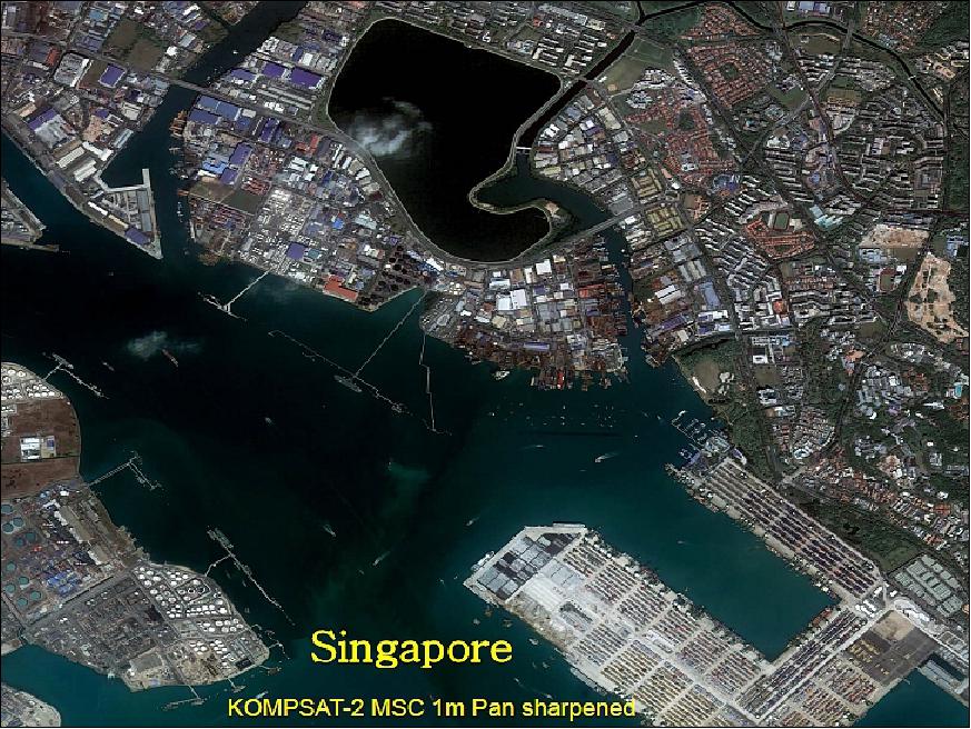

• In January 2012, KOMPSAT-2 has been confirmed as an ESA Third Party Mission (TPM) for the next 2 years, and approved scientific users will have the possibility to order KOMPSAT-2 data from the archive up to a total of 3000 products. 35)
• In June 2011, an orbit correction manoeuvre was conducted to satisfy the POD (Precise Orbit Determination) accuracy requirements of 2-3 m rms (1σ). 36)
• The KOMPSAT-2 spacecraft and its payload are operating nominally in 2011.
• The KOMPSAT-2 spacecraft and its payload are operating nominally in 2010. With a design life of 3 years, KOMPSAT-2 has successfully completed its nominal mission lifetime, and now its mission is extended for further services to the users. 37)
• Spot Image operates a multimission ground segment, referred to as HMA (Heterogeneous Mission Access), integrating SPOT series missions (SPOT-4/ -5) along with FormoSat-2, KOMPSAT-2, and in the future also with Pleiades and SPOT-6/-7 (Astroterra) spacecraft data. 38)
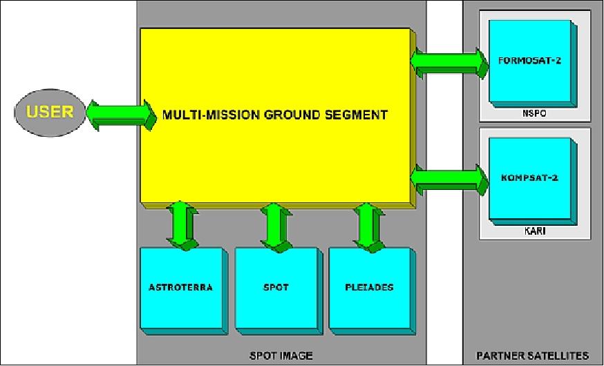
• KOMPSAT-2 is also an ESA TPM (Third Party Mission). In general KOMPSAT-2 observations over Europe are shared between ESA (Cat-1 users) and Spot Image (commercial users). From 2008-2010 (and possibly beyond) ESA is offering data for research and application development:
- Archived KOMPSAT-2 data since 2006 (on-demand production)
- New KOMPSAT-2 data (on-demand acquisition and production)
• The KOMPSAT-2 geometric accuracy verification was successfully evaluated from 2007 through 2008. The 121 test sites provided excellent conditions for geometric verification due to their flat terrain and very good grid infrastructure. 39) 40)
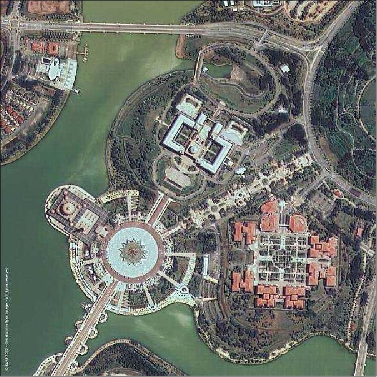
• KOMPSAT-2 completed its commissioning phase in late September 2006 and started its nominal operations phase in October 2006.
• In August, 2006, KOMPSAT-2 had provided its first images.
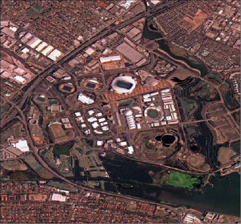
• On Oct. 24, 2005, KARI made Spot Image (France) the exclusive distributor of imagery from the KOMPSAT-2 Earth observation satellite - except for customers from Korea, the United States, and the Middle East, which are being serviced by KAI Image Inc. of Korea.
Note: As of July 15, 2008, EADS's Astrium Services unit has acquired a majority stake (81%) in Spot Image (from CNES). - In January 2011, Astrium fully integrated Spot Image and Infoterra into the new GEO-Information business division. 41)
Sensor Complement
MSC (Multi-Spectral Camera)
MSC is a joint development of KARI with ELOP (Electro-Optics Industries Ltd. of Rehovot, Israel) and OHB-System, Bremen, Germany. The objective is to collect high-resolution panchromatic and multispectral imagery of the Earth's surface (simultaneous observation). ELOp of Elbit Systems refers to the camera as Uranus-MSC. 42)
MSC is an optoelectronic linear pushbroom instrument with a single nadir-pointing telescope. The Pan band has a spectral range of 500-900 nm, the four MS bands are in the 450-900 nm range. The GSD (Ground Sample Distance) of the Pan data is 1 m (GSD), the MS data has a GSD of 4 m. The swath width is 15 km. A FOR (Field of Regard) of ±30º in pitch and up to ±56º in the roll direction is provided through spacecraft body pointing. MSC has a duty cycle of 20%. 43) 44) 45) 46) 47) 48) 49) 50)
The EFL (Effective Focal Length) of the optics subsystem is 9000 mm for the Pan band, and 2250 mm for the MS bands.
Parameter | Value | Parameter | Value |
Spectral range Pan | 500-900 nm | Spectral range MS | 450-520, 520-600, 630-690, 760-900 nm |
GSD (Ground Sample Distance) | Pan (1 m), MS (4 m) | Spectral bands | 1 Pan + 4 MS |
Swath width, FOV | 15 km at nadir, ±0.62º | SNR | > 100 |
MTF (Modulation Transfer Function) | > 15% for Pan, | Data quantization | 10 bit |
Detector line array | 15,000 pixels (Pan) | Detector line array | 3,750 pixels (MS) |
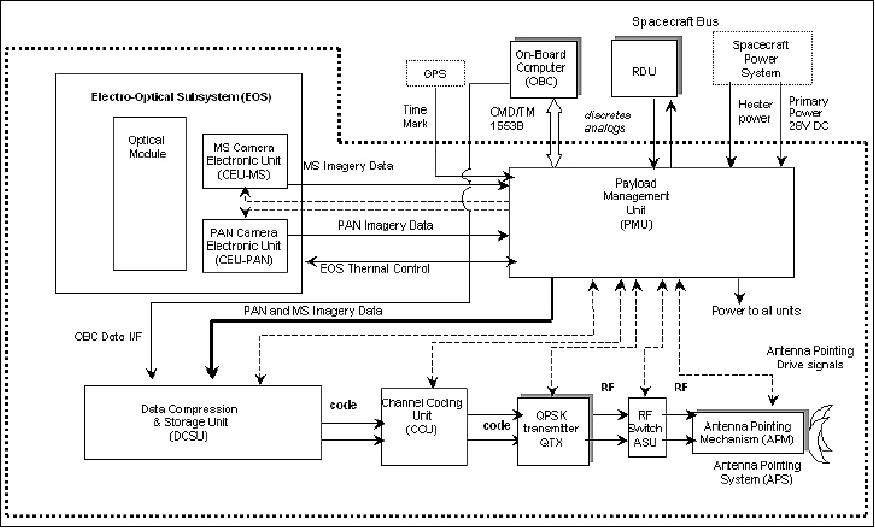
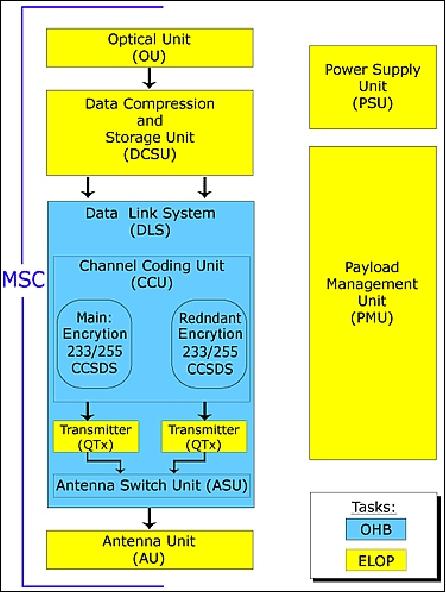
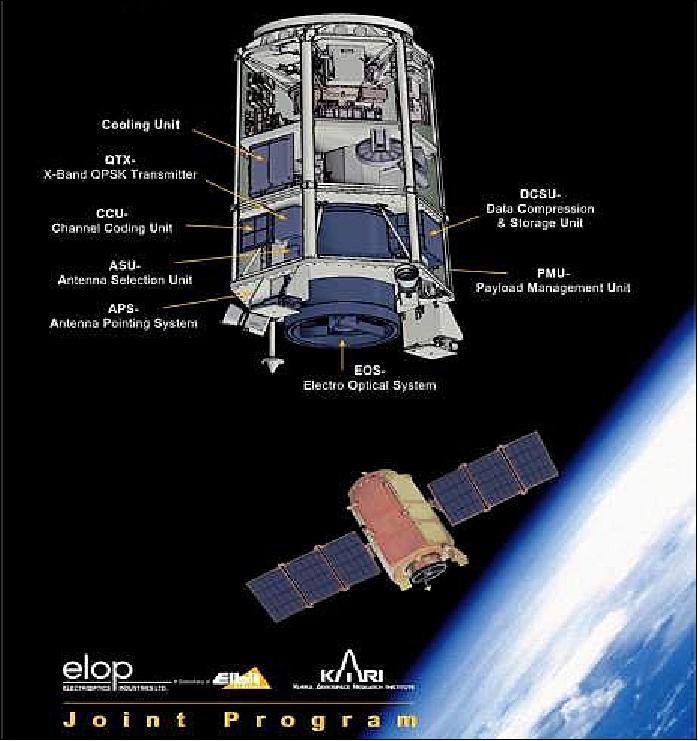
The MSC consists of the following elements: EOS (Electro-Optical Subsystem), PDTS (Payload Data Transmission Subsystem), PMU (Payload Management Unit), and the interconnection harness.
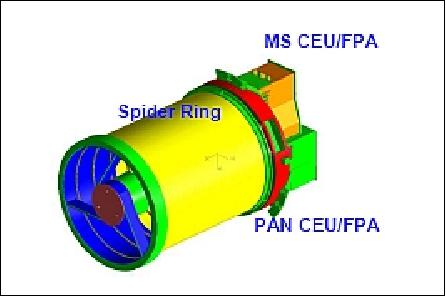
• EOS itself comprises the optical module including optical components and optical structure, Pan FPA (Focal Plane Assembly), MS FPA, and two CEU (Camera Electronics Unit), CEU-Pan and CEU-MS. A Ritchey-Chretien telescope type with a large aperture (60 cm diameter) is being used.
• PDTS consists of DCSU (Data Compression Storage Unit), DLS (Data Link System) including CCU (Channel Coding Unit), QTX (QPSK Transmitter), and APS (Antenna Pointing System).
The PMU controls the overall MSC system, using dedicated communication channels (RS-422); it communicates with the spacecraft via the MIL-STD-1553B bus. MSC operations support includes programmable gain and offsets to allow for in-flight adaptation of the instrument sensitivity to the landscape luminosity. Gains and offsets are selectable by command. In addition, MSC provides a calibration function. Actually, there are three different calibration functions: 1) the radiometric, 2) NUC (Non-Uniformity Correction), and 3) the focus calibration function in order to use the image data accurately. 51) 52)
TDI (Time Delay Integration) techniques are being employed for panchromatic imagery up to level 32 to enhance the SNR and support observations in low-light conditions. MSC features the support modes of a) automatic normal operation and b) of stereo imaging. The latter is accomplished by the agility of the spacecraft, i.e. tilting the S/C either in roll (up to ±56º) and/or in pitch (up to ±30º).
The control parameters of MSC are:
• Line rate change: the CCD line rate can be changed in the range from 7100 to 2200 during stereo imaging to reduce the degradation of the imagery due to smear effects. An appropriate line rate setting is advantageous to minimize any degradation of the image quality.
• Gain and offset
• Number of sectors for the recording of source data
• Compression ratio
• Encryption ratio
• Quantization table
Future: The KOMPSAT-3 project development started in 2004 at KARI for a projected launch in 2011 (Note: KOMSAT-3 was launched on May 17, 2012). The optical imager on this satellite will have a GSD (Ground Sample Distance) of 0.7 m.
Ground Segment
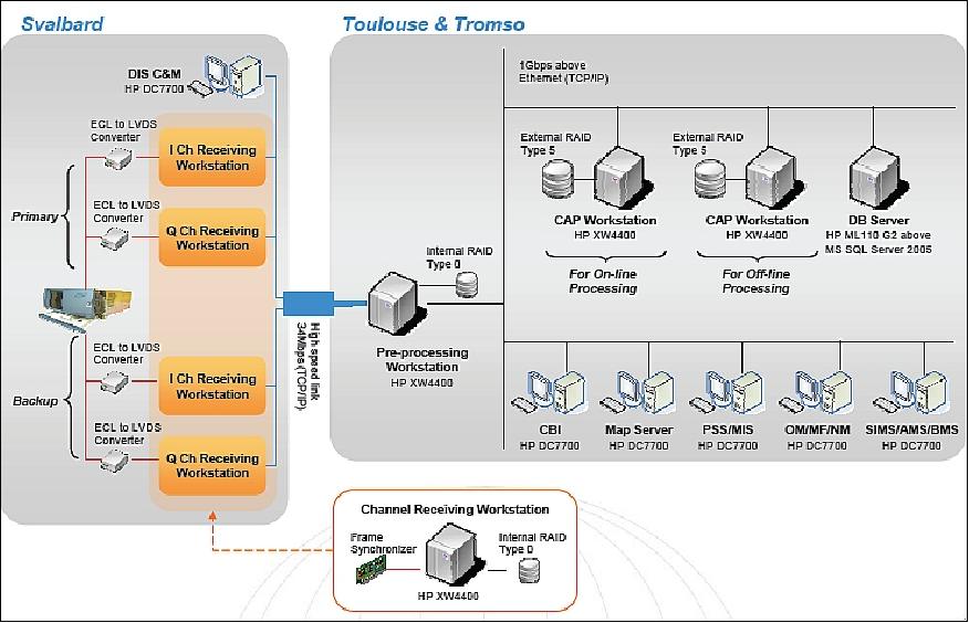
Mission operations are performed at KMOC (Korea Aerospace Research Institute Mission Operation Center). The KGS (KOMPSAT Ground Station) is located at KARI, Daejeon, South Korea. In addition, there is a second ground station at ETRI (Electronics and Telecommunications Research Institute) in South Korea. Each site is comprised of MCE (Mission Control Element) and IRPE (Image Reception and Processing Element). MCE monitors and controls the satellite and provides mission planning. Mission control provides also operational orbit determination/prediction and the POD (Precise Orbit Determination) function.54) 55) 56)
In the meantime, the KOMPSAT ground segment has become a multi-mission facility to accommodate also the operations requirements of the future missions under development, namely KOMPSAT-5 (SAR payload, launch in late 2010) and KOMPSAT-3 (optical payload, launch in 2011). The final goal of multi-satellite operations is to reduce the operational cost while concurrently maximising the operational stability ensuring the safety of the satellite and operational efficiency, i.e. do more with less. 57)
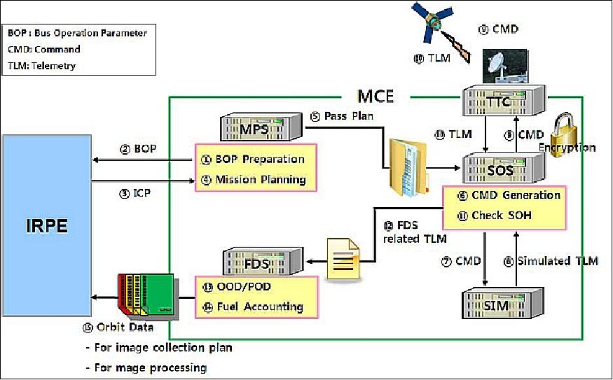
The MCE system consists of five subsystems:
- TTC (Tracking, Telemetry and Command Subsystem). TTC provides the S-band uplink and downlink communications interface with satellite, CCSDS command and telemetry processing and tracking capabilities.
- SOS (Satellite Operations Subsystem). SOS provides spacecraft command generation and execution, a satellite state of health monitoring and housekeeping telemetry data processing. Use of TMAS (Telemetry Monitoring and Analysis System). 59)
- MPS (Mission Planning Subsystem). MPS provides satellite mission planning, incorporates user requests, prepares bus operation parameters including bus activity, defines and manages the configurations of the satellite, and prepares operating schedules. MPS is also referred to as MAPS (Mission Planning and Analysis Subsystem).
- FDS (Flight Dynamics Subsystem). FDS provides satellite flight dynamics operation support functions such as orbit determination, orbit prediction, and antenna pointing data generation for satellite tracking.
- SIM (Satellite Simulator Subsystem). SIM provides support functions rather than direct operational functions such as anomaly resolution support and operating personnel training.
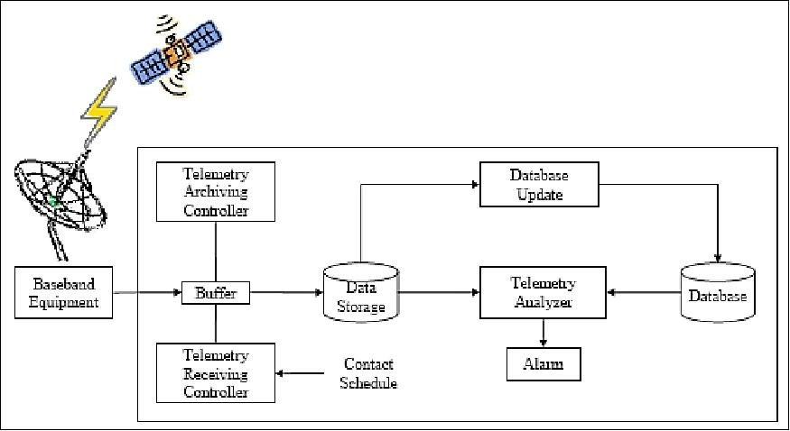
TMAS (Telemetry Monitoring and Analysis System): KARI developed TMAS capable of performing such tasks as telemetry processing, trend analysis and reporting activities automatically. This automation scheme considerably reduces operational costs by eliminating many repetitive processes and allows operators to concentrate on special situations which require human intervention.
The key functions of TMAS are as follows: (Ref. 59)
- Telemetry receiving and archiving in accordance with the contract schedule
- Telemetry limit violation check
- Trend Analysis based on the computation of daily statistics
- Report file generation and distribution to the MOT and the related engineering staff.
TMAS is composed of a common module and a mission-unique module. The common module includes the connection module, analysis module and report module. The mission-unique module includes the parsing module that consists of the database and the processing algorithm in accordance with the mission-unique processing scheme.
The modular implementation of TMAS permits also the support of future missions such as KOMPSAT-5 and KOMPSAT-3, which are scheduled to be launched in 2010 and 2011, respectively.
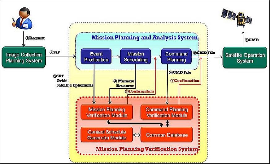
MAPS predicts satellite orbital events that affect the satellite mission operations and generates a conflict-free pass plan for the satellite operations. MAPS was designed to make a plan of up to 20 imaging requests per day. Since KARI contracted with SPOT Image on 1 June 2007, the amount of imaging acquisition requests has been on the increase. In order to meet the demands of lots of satellite mission planning activities, KARI developed a software called MPVS (Mission Planning Verification System) that is capable of verifying the results of mission planning. The development of MPVS is aimed at reducing operational risk and increasing the efficiency of operations. 60)
The key functions of MPVS are aimed at the verification of mission planning and command planning results created by MAPS. MPVS consists of three main modules, including:
- CSG (Contact Schedule Generation) module,
- MPV (Mission Planning Verification) module,
- CPV (Command Planning Verification) module.
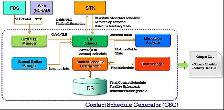
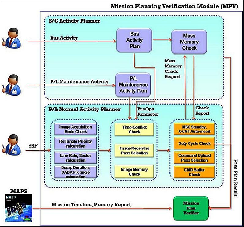
The CSG module is to predict the ground contact time that is used for MPV and CPV. The MPV module is to verify the pass plan that is generated in the MAPS with the results of mission scheduling processing. The CPV module is to verify the command plan that will be uploaded to the satellite through SOS (Satellite Operations Subsystem).
Contact schedule generation:
MPVS requires a realistic and accurate ground contact time to check the constraints. The CSG module has the capability to generate the ground contact time considering several conditions such as the ground mask angle, operational limitations of the ground stations and the satellite. A user can flexibly configure the setup file in accordance with the change of operational condition concept. Figure 2 represents the architecture of the CSG module.
MPV (Mission Planning Verification): KARI considers two basic mission planning activity types: One is named "Payload normal activity" which is related to routine imaging activities. The other is named "Spacecraft activity" and includes all activities except routine imaging activities. For example, it includes the onboard data dump, ephemeris upload and orbit manoeuvre for the maintenance of satellite orbit, and parameter upload for the maintenance of payload. The automated verification using MPV is performed for only "Payload normal activity" based on the SRF (Schedule Request File). The verification of "Spacecraft activity" can be done manually by users if needed.
FDS (Flight Dynamics Subsystem):
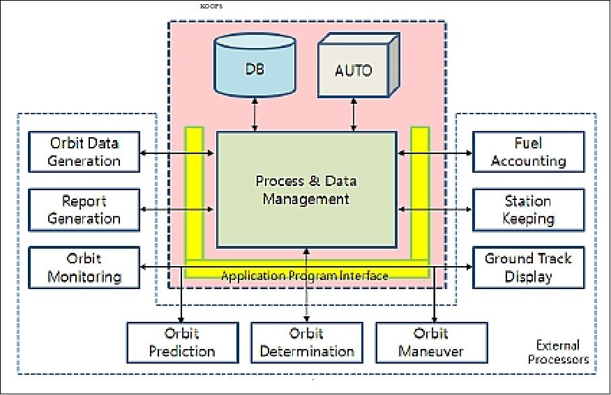
The FDS supports operational orbit determination, precise orbit determination, precise orbit ephemeris generation, antenna pointing data generation, etc. KARI developed KOOPS (KOMPSAT's automated Operational Orbit Processing System) to support the various FDS tasks on a daily basis. KOOPS determines the orbit and evaluates its result using pre-defined criteria, and generates the orbit data automatically based on the execution schedule. The automated system integrates all of the components of several routine processes which are necessary for daily flight dynamics activities (Ref. 37).
The automation scheme in KOOPS, implemented for a multi-mission support, reduces considerably the operational risk and cost by eliminating many repetitive processes and allows engineers to concentrate on non-nominal situations which require human intervention. Additionally, the operational stability and efficiency of the flight dynamics supports are significantly enhanced.
Data Distribution
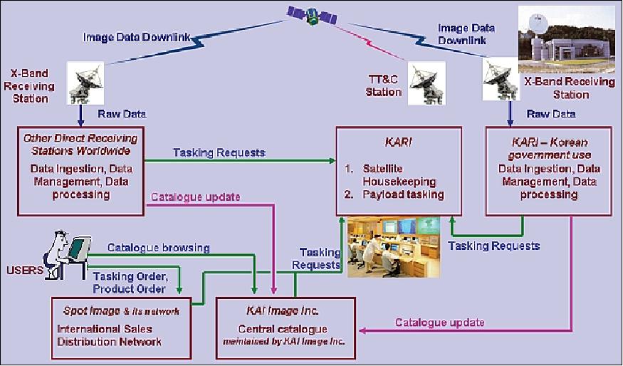
• On the domestic scene (Korea) KAI Image Inc. is the commercial distributor of KOMPSAT-2 data. 61)
• SPOT Image S. A. (Toulouse, France) is the exclusive commercial distributor of KOMPSAT-2 imagery (except for customers in Korea, the United States and the Middle East) with data reception via its own acquisition stations.
References
1) Information provided by Young-Min Cho of KARI
2) S.-R. Lee, H.-J. Kim, J.-J. Lee, Z.-C. Kim, "System Design of the KOMPSAT-2," 6 th Asia-Pacific Conference on Multilateral Cooperation in Space Technology and Applications (APC-MCSTA), Sept.. 18-21, 2001, Beijing, China
3) S.-R. Lee, J.-S. Ryoo, "Conceptual Design of the KOMPSAT-2 System." 22nd International Symposium on Space Technology and Science, Morioka, Japan, May 28-June 4, 2000
4) B.-S. Kim, H. S. Kim, G. W. Morgenthaler, "The KOMPSAT Program to Provide Various Applications in the Field of Earth Observation covering Land, Sea, and Coastal Zones," Proceedings of the 56th IAC 2005, Fukuoda, Japan, Oct. 17-21, 2005, IAC-05-B1.1.06
5) K. Lee, Y. Kim, B. Hoersch, "KOMPSAT & PROBA Data Applications," Proceedings of the 3rd CHRIS/PROBA Workshop, ESA/ESRIN, Frascati, Italy, March 21-23, 2005, ESA SP-593, June 2005
6) "Korea Multi-purpose Satellite (KOMPSAT)," URL: http://www.globalsecurity.org/space/world/rok/kompsat.htm
7) S.-W. Rhee, H.-J. Kim, J.-J Lee, "KOMPSAT-2 Attitude & Orbit Control System Development," Proceedings of IAC 2004, Vancouver, Canada, Oct. 4-8, 2004, IAC-04-IAA-4.11.1.03
8) Science and Technology Satellite Program of KOREA, Nov. 2, 2004, KARI, URL: http://www.aprsaf.org/data/p_saprsaf_data/
repo_ap11cd/ss_info/4_SS_STSAT.pdf
9) S.-W. Rhee, J.-J. Lee, "On-Orbit Performance of KOMPSAT-2 Attitude & Orbit Control System," Proceedings of the 21st Annual AIAA/USU Conference on Small Satellites, Logan, UT, USA, Aug. 13-16, 2007, SSC07-VII-9
10) J.-S. Lee, B.-S. Lee, J. Kim, S.-P. Lee, "Precise Orbit Determination by DGPS Technique for the Korea Multi-Purpose Satellite-2," SpaceOps 2002, Oct. 9-12, 2002, Houston, TX, USA
11) D.-W. Chung, S.-R. Lee, S.-J. Lee, "KOMPSAT-2 Orbit Determination using GPS Signals," Proceedings of GNSS (Global Navigation Satellite System) 2004, Dec. 6-8, 2004, Sidney, Australia
12) "KOMPSAT-2, Eurockot's First Mission for the Republic of Korea," Eurockot, URL: http://www.eurockot.com/missions/launch-record/kompsat-2/
13) Information provided by Sungdong Park, Chairman, Satrec Initiative Co., Ltd., Daejeon, Korea.
14) Information provided by Moongyu Kim, President & CEO of SIIS (SI Imaging Services), Daejeon, Korea
15) Information provided by Sang-Ryool Lee of KARI, Daejeon, Korea.
16) "Korea Multi-purpose Satellite 2 Successfully Completes 9-Year Mission," KARI News Release, Oct. 6, 2015, URL: http://www.kari.re.kr/cop/bbs/BBSMSTR_000000000031/
selectBoardArticle.do?nttId=1204&kind=&mno
=sitemap_02&pageIndex=1&searchCnd=&searchWrd=
17) "Caspean Sea," ESA, 'Earth observation image of the week,' Jan. 16, 2015, URL: http://www.esa.int/spaceinimages/Images/2015/01/Caspian_Sea
18) "Quelccaya ice cap, Peru," ESA image featured in the Earth from Space video program, Nov. 28, 2014, URL: http://www.esa.int/spaceinimages/Images/2014/11/Quelccaya_ice_cap_Peru
19) "Egmont National Park, New Zealand," ESA image, featured in the Earth from Space program, released on Oct. 31, 2014, URL: http://www.esa.int/spaceinimages/Images/2014/10/Egmont_National_Park_New_Zealand
20) "Southern Dardur, Sudan," ESA, Earth from space program, released Oct. 10, 2014, URL: http://www.esa.int/spaceinimages/Images/2014/10/Southern_Darfur_Sudan
21) "Mexico City," ESA, Image of the Week, released on July 18, 2014, URL: http://www.esa.int/spaceinimages/Images/2014/07/Mexico_City
22) "Valley of Mexico," Wikipedia, URL: http://en.wikipedia.org/wiki/Valley_of_Mexico
23) "Dasht-e Lut desert detail," ESA, Image of the Week, released on June 19, 2014, URL: http://www.esa.int/spaceinimages/Images/2014/06/Dasht-e_Lut_desert_detail
24) "Haa Alif Atoll, Maldives," ESA, released on June 5, 2014, URL: http://www.esa.int/spaceinimages/Images/2014/06/Haa_Alif_Atoll_Maldives
25) "Zaatari Refugee Camp, Jordan," ESA, May 23, 2014, URL: http://www.esa.int/spaceinimages/Images/2014/
05/Zaatari_Refugee_Camp_Jordan
26) "Imja glacier, Himalayas," ESA, March 14, 2014, URL: http://www.esa.int/spaceinimages/Images/2014/03/Imja_glacier_Himalayas
27) Cheong-Gil Jin, Sun-Gu Lee, "Cross-calibration for KOMPSAT-2 MSC images using EO-1 Hyperion," Proceedings of ISRS 2014 (International Symposium on Remote Sensing 2014), Busan, Korea, April 16-18, 2014
28) "Jeddah's seaport, Saudi Arabia," ESA, Feb. 7, 2014, URL: http://www.esa.int/spaceinimages/Images/2014/02/Jeddah_s_seaport_Saudi_Arabia
29) "Earth from Space: Amazon," ESA, October 18, 2013, URL: http://www.esa.int/Our_Activities/Observing_the_Earth/Earth_from_Space_Amazon
30) "The Palouse Region," ESA 'Space in Images', April 8-12, 2013, URL: http://spaceinimages.esa.int/Images/2013/04/The_Palouse_region
31) "Satrec Initiative Announces Agreement with Korea Aerospace Research Institute," Satrec Initiative, Nov. 15, 2012, URL: https://www.spacedaily.com/reports/Satrec_Initiative_Announces_Agreement_with_Korea_Aerospace_Research_Institute_999.html
32) Hyo-Suk Lim, "Country Report of Korea," Proceedings of APRSAF-18 (18th Session of the Asia-Pacific Regional Space Agency Forum), Singapore, Dec. 6-9, 2011, URL: http://www.aprsaf.org/annual_meetings/aprsaf18/
pdf/program/day3/12_Country_Report_Korea_hslim.pdf
33) Chin Young Hwang, "Recent Remote Sensing Activities in the Republic of Korea," Proceedings of the 49th Session of UNCOPUOS-STSC (UN Committee on the Peaceful Uses of Outer Space-Scientific and Technical Subcommittee), Vienna, Austria, Feb. 6-17, 2012, URL: http://www.oosa.unvienna.org/pdf/pres/stsc2012/tech-24E.pdf
34) "Earth from Space: Island Mountain," ESA observing the Earth, Sept. 6, 2013, URL: http://www.esa.int/Our_Activities/Observing_the_Earth/
Earth_from_Space_Island_mountain
35) https://earth.esa.int/web/guest/missions/3rd-
party-missions/current-missions/kompsat-2
36) Ok-Chul Jung, Jung-Hoon Shin, Su-Jin Choi, Dae-Won Chung, Eun-Kyu Kim, Hak-Jung Kim, "Analysis on the Long-term Orbital Evolution and Maintenance of KOMPSAT-2," Proceedings of SpaceOps 2012, The 12th International Conference on Space Operations, Stockholm, Sweden, June 11-15, 2012, URL: http://www.spaceops2012.org/proceedings/
documents/id1259558-Paper-001.pdf
37) Ok-Chul Jung, Su-Jin Choi, Dae-Won Chung, Yong-Sik Chun, Hak-Jung Kim, "Automated Flight Dynamics Operations for KOMPSAT-2," Proceedings of the SpaceOps 2010 Conference, Huntsville, ALA, USA, April 25-30, 2010, paper: AIAA 2010-2330
38) Igor Lampin, Didier Giacobbo, "FormoSat-2, KOMPSAT-2, AstroTerra," GSCB (Ground Segment Coordination Body) Workshop, ESA/ESRIN, Frascati, Italy, June 18-19, 2009
39) Doo Chun Seo, Ji Yeon Yang, Dong Han Lee, Jeong Heon Song, Hyo Suk Lim, "KOMPSAT-2 direct sensor modeling and geometric calibration/validation," ISPRS 2008, Beijing, China, July 3-11, 2008, URL: http://www.isprs.org/proceedings/XXXVII/congress/1_pdf/08.pdf
40) Dong-Han Lee, D. C. Seo, J. H. Song, M. J. Choi, H. S. Lim, "Summary of calibration and validation for KOMPSAT-2,"The International Archives of the Photogrammetry, Remote Sensing and Spatial Information Sciences,. Vol. XXXVII., Part B1,. Beijing, China, 2008, URL: http://www.isprs.org/proceedings/XXXVII/congress/1_pdf/09.pdf
41) "Astrium fully integrates Spot Image and Infoterra into new GEO-Information business division," Astrium, Dec. 1, 2010, URL: https://web.archive.org/web/20130403004609/http://www.astrium.eads.net/en/press_centre/astrium-fully-integrates-spot-image-and-infoterra-into-new-geo-information.html
42) Ilan Porat, "ELOP in Space," Elbit Systems, 5th session International Conference on Space-based Techologies for Risk Management, UNOOSA (United Nations Office for Outer Space Affairs), New York, Nov. 25-27, 2013, URL: http://asri.technion.ac.il/files/2013/12/UN-space-nov-2013_1.pdf
43) S.-S. Yong, S.-W. Ra, "The Design of MSC (Multi-Spectral Camera) System Operation," Proceedings of IGARSS 2004, Anchorage, AK, USA, Sept. 20-24, 2004
44) S.-S. Yong, J.-P. Kong, H.-P. Heo, Y. S. Kim, H.-Y. Paik, "The Analysis of MSC (Multi-Spectral Camera) Operational Parameter," Proceedings of International Symposium on Remote Sensing 2001, Seogwipo, Korea, Oct. 31 - Nov. 2, 2001, pp. 198-203
45) S.-S. Yong, J.-P. Kong, H.-P. Heo, Y. S. Kim, "The Analysis of MSC (Multi-Spectral Camera) Operational Parameters," Korean Journal of Remote Sensing, Vol.18, No.1, 2002, pp.53-59
46) S.-S. Yong, H. P. Heo, "The electrical design of MSC(Multi-Spectral Camera)," Proceedings of International Symposium on Remote Sensing 2000, Kyongju, Korea, Nov. 1-3, 2000, Kyongju, Korea pp. 148-152.
47) E.-S. Lee, D.-G. Lee, S.-H. Lee, "Opto-mechanical design and analysis of the MSC on the KOMPSAT-2," Proceedings of SPIE, Vol. 6024, ICO20: `Optical Devices and Instruments,' James C. Wyant, Xuejun Zhang, Editors, 60241U, Jan. 25, 2006, doi:10.1117/12.666876
48) Y.-S. Kim, D.-K. Lee, C.-H. Lee, S.-H. Woo, "Reliability Analysis of the MSC System," Journal of Astronomy and Space Sciences, Vol. 20, No 3, pp. 217-226, 2003
49) http://envisat.esa.int/earth/www/object/index.cfm?fobjectid=5683
50) "KOMPSAT-2 Image data Manual," KARI, January 25, 2008, Version 1.1, URL: http://earth.esa.int/pub/ESA_DOC/K2_IDM_ver1.1_Full.pdf
51) S.-S. Yong, S.-H. Lee, S.-R. Lee, S.-W. Ra, A. Guberman, M. Berger, "The Concept and preparation of MSC(Multi-Spectral Camera) System Calibration Operation," SpaceOps 2006 Conference, Rome, Italy, June 19-23, 2006, AIAA 2006-5790
52) Sang-Soon Yong, Hae-Jin Choi, Sung-Woong Ra, "The initial checkout of MSC (multi-spectral camera) system," Proceedings of SPIE, Sensing Technologies III, Sept. 15-19, 2007, Florence, Italy, Vol. 6744, 67441X (2007); DOI:10.1117/12.740069
53) Tal Dekel, "Israeli Civilian Space Program: Turning Swords into Plowshares," Proceedings of the 49 Session of COPUOS (Committee on the Peaceful Uses of Outer Space), STSC (Scientific and Technological Subcommittee), Vienna, Austria, Feb. 6-17, 2012, URL: http://www.oosa.unvienna.org/pdf/pres/stsc2012/tech-06E.pdf
54) J. Kim, W. C. Jung, B.-S. Lee, S. Lee, "KOMPSAT-2 Mission Control Element System," Proceedings of WSANE 2005 (Workshop for Space Aeronautical and Navigational Electronics), Daejeon, Korea, March 3-5, 2005, pp. 37-42
55) M.-G. Kim, T.-J. Kim, H.-J. Choi, S.-O. Park, D.-H. Lee, Y.-J. Im, J.-H. Shin, M.-J. Choi, S.-R. Park, J.-J. Lee, "Ground Receiving System for KOMPSAT-2," Korean Journal of Remote Sensing, Vol.19, No.3, 2003, pp.191-200
56) Myeong-Shin Lee, Dae-Hwan Hyun, Hyun-Chul Baek, Sun-ju Park, Dae-Won Chung, Eun-Kyu Kim, "The Training Concept Status and Improvement Strategy for Flight Operation Team of KOMPSAT," Proceedings of SpaceOps 2012, The 12th International Conference on Space Operations, Stockholm, Sweden, June 11-15, 2012, URL: http://www.spaceops2012.org/proceedings/
documents/id1275497-Paper-002.pdf
57) Ok-Chul Jung, Dae-Won Chung, Sun-Ju Park, Dae-Hwan Hyun, Yong-Sik Chun, "Advanced Concept and Design of the Multi-satellite Operations System," Proceedings of the SpaceOps 2010 Conference, Huntsville, ALA, USA, April 25-30, 2010, paper: AIAA 2010-2333
58) Igor Lampin, "Ground Segment Coordination Body Workshop 2007, FormoSat-2, KOMPSAT-2, Astroterra," Frascati, Italy, June 19-20, 2007, URL: http://earth.esa.int/gscb/papers/22_Lampin.pdf
59) Mekong-Shin Lee, DEA-Won Chung, Hun-Churl Baek, Young-Wok Kim, Yong-Ki Kim, "Telemetry Monitoring and Analysis System for KOMPSAT-2 Operations," Proceedings of the SpaceOps 2010 Conference, Huntsville, ALA, USA, April 25-30, 2010, paper: AIAA 2010-2311
60) Sun-Ju Park, Dae-Won Chung. Jung-Hoon Shin, Ji-Marn Lee, Jae-Hyun Lee, "Mission Planning Verification System for KOMPSAT-2 Operations," Proceedings of the SpaceOps 2010 Conference, Huntsville, ALA, USA, April 25-30, 2010, paper: AIAA 2010-2128
61) Hyo-Suk Lim, "Applications of KOMPSAT Data and Space Program of Korea," URL: http://www.aprsaf.org/data/vietnam_ws/vws_14.pdf
The information compiled and edited in this article was provided by Herbert J. Kramer from his documentation of: "Observation of the Earth and Its Environment: Survey of Missions and Sensors" (Springer Verlag) as well as many other sources after the publication of the 4th edition in 2002. - Comments and corrections to this article are always welcome for further updates (eoportal@symbios.space).
Spacecraft Launch Mission Status Sensor Complement Ground Segment References Back to Top