KOMPSAT-3 (Korea Multi-Purpose Satellite-3) / Arirang-3
EO
High resolution optical imagers
Land
Multi-purpose imagery (land)
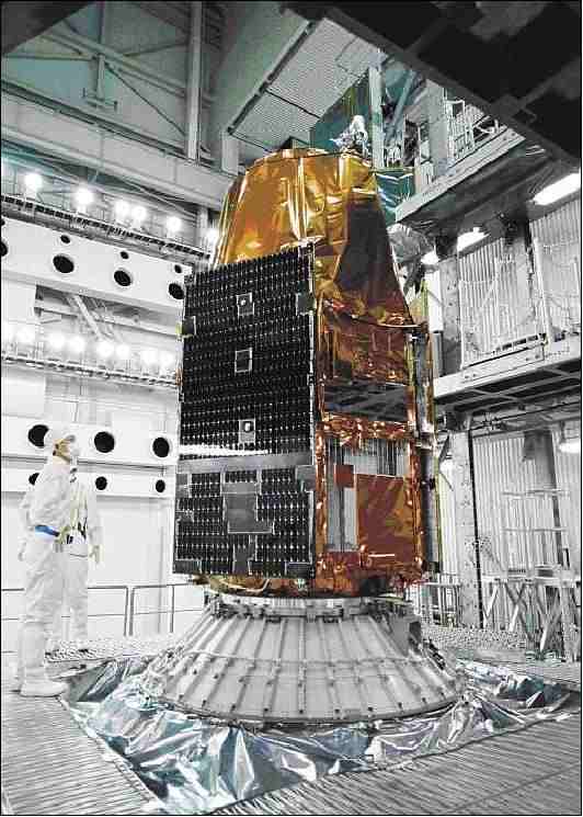
KOMPSAT-3 is a Korean Earth observation mission of KARI (Korea Aerospace Research Institute), funded by the Ministry of Education, Science and Technology (MEST), which launched in May, 2012. The mission aims to meet Korea’s demand for high-resolution optical imagery, in the form of Geographical Information Systems (GIS), for applications in environmental, oceanographic and agricultural monitoring.
Quick facts
Overview
| Mission type | EO |
| Agency | KARI, ASTRIUM |
| Mission status | Operational (extended) |
| Launch date | 18 May 2012 |
| Measurement domain | Land |
| Measurement category | Multi-purpose imagery (land), Vegetation, Landscape topography |
| Measurement detailed | Land surface imagery, Vegetation type, Land surface topography |
| Instruments | AEISS |
| Instrument type | High resolution optical imagers |
| CEOS EO Handbook | See KOMPSAT-3 (Korea Multi-Purpose Satellite-3) / Arirang-3 summary |
Summary
Mission Capabilities
KOMPSAT-3 carries a single instrument, AEISS (Advanced Electronic Image Scanning System), a high resolution optical imager applicable in cartography and disaster monitoring. The instrument collects data in landscape topography, multi-purpose imagery (land) and vegetation. The satellite also has an electro-optical subsystem (EOS) that enables images to be captured at the optimal temperature condition.
Performance Specifications
AEISS has a swath width of 15 km at nadir and a focal length of 8.6 m. The system has a total of five bands, one panchromatic band (450nm - 900 nm), and four multispectral bands ( blue (450 nm - 520 nm), green (520 nm - 600 nm), red(630 nm - 690 nm) and near-infrared (NIR) (760 nm - 900 nm)). The instrument has a ground sample distance of 0.7 m for the panchromatic band at nadir, and 2.8 m for multispectral bands at nadir. AEISS also has a signal-to-noise ratio of greater than 100 for panchromatic and multispectral imaging, and a spatial resolution of 0.7 m.
KOMPSAT-3 operates in a sun-synchronous orbit of altitude 685 km, inclination 98.1° and LST (Local Solar Time) of 1050 hours. It also has an orbit period of 98.5 minutes, and a repeat cycle of 28 days.
Space and Hardware Components
The ground segment of the Korea Aerospace Research institute (KARI) consists of two distinct elements that support the mission processes and maintain the health of the satellite. The mission and control element (MCE) provides the planning and satellite command, control functions and the maintenance of the satellite systems. The Image Reception and Processing Element (IPRE) provides data reception and storage processes of KOMPSAT-3 spatial data and allows for the distribution of imagery products to end-users. There are four subsystems, the User Interface Subsystem (UIS) the Image Collection Planning Subsystem (ICPS), the Direct Ingestion subsystem (DIS) and the Product Management Subsystem (PMS) which collectively form the Image Reception and Processing Station (IRPS), centred around end-user interfacing.
KOMPSAT-3 (Korea Multi-Purpose Satellite-3) / Arirang-3
Spacecraft Launch Mission Status Sensor Complement Ground Segment References
KOMPSAT-3 is an optical high-resolution Korean observation mission of KARI (Korea Aerospace Research Institute). The mission is funded by MEST (Ministry of Education, Science and Technology). The project was started in 2004. The objective is to provide observation continuity from the KOMPSAT-1 and KOMPSAT-2 missions to meet the nation's needs for high-resolution optical imagery required for GIS (Geographical Information Systems) and other environmental, agricultural and oceanographic monitoring applications.
A further goal is to meet the nation's satellite demand and form a technology infrastructure that will make inroads into the world space industry at a stage when the industry is improving the capability to design and develop highly advanced remote sensing satellites.
Spacecraft
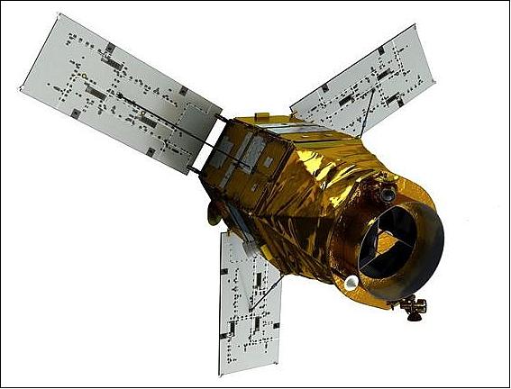
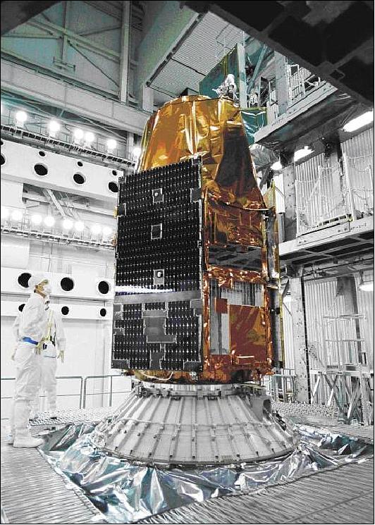
The KOMPSAT-3 spacecraft bus design, development and integration is being led at KARI. The spacecraft is 3-axis stabilized. The agile spacecraft features a body pointing capability of ±45º into any direction (cross-track or along-track). This satellite agility permits event monitoring as well as single-pass stereoscopic observations. 1) 2) 3)
SI (Satrec Initiative) of Daejeon participation in the KOMPSAT-3 development of KARI: 4) 5)
- SI provided the DM (Development Model) of power controller, and on-board computer processor module as well as six FM coarse sun sensors to KARI. Image Receiving and Processing Station and several key subsystems of Mission Control Station is currently being developed.
- SI developed OBC (On-Board Processor) module with reliable RTOS and high-end CPU. SI developed a space qualified processor module based on TSC695F CPU (ERC32).
- SI was contracted by KARI to develop PADS ( Precision Attitude Determination Software) of KOMPSAT-3. PADS is a software package which performs precision attitude determination by using precise orbit data and attitude sensor data (star trackers and gyros). This software estimates all sensitive parameters including misalignment angle between each sensor and optical bench, the drift rate error and scale factor error of each gyro and etc. PADS includes simulated sensor data generator, data analysis tools, validation tools as well as animation tools.
The KOMPSAT-3 SADM (Solar Array Deployment Mechanism) was the first flight hardware contract for SpaceTech GmbH of Immenstaad, Germany signed in 2005/2006 with Korean Airlines Ltd. The deployment mechanism is based on an earlier patented design by SpaceTech exhibiting very low friction, high torque margin and at the same time low deployment shock through a cam/spring driven system. The contract also included the delivery of stiffening mechanism for each of the solar arrays, to achieve a high eigenfrequency of the solar array wings in order to allow agile satellite operation/pointing. 6)
Spacecraft mass, power | ~980 kg; 1.3 kW |
Spacecraft size | 3.5 m height, 2.0 m diameter |
Spacecraft design life | 4 years |
Stabilization | 3-axis stabilized |
RF communications: The S-band is used for TT&C communications. The X-band is used to downlink the payload data.
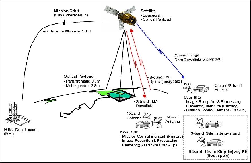
Launch: The KOMPSAT-3 (Arirang-3) spacecraft was launched as a "co-payload" on May 17, 2012 (16:39 UTC) from the Tanegashima Space Center of JAXA, Japan on the H-IIA launch system. The primary payload on this flight was GCOM-W1 (Global Change Observation Mission - Water 1) of JAXA (nickname: Shizuku) with a launch mass of ~ 1990 kg. Launch provider: Mitsubishi Heavy Industries, Ltd. 7) 8) 9)
A contract between the launch service provider MHI (Mitsubishi Heavy Industries, Ltd.) and KARI was signed in January 2009. This represents the first satellite launch services order placed to MHI by an overseas customer. 10)
Further secondary payloads are:
• SDS-4 (Small Demonstration Satellite-4) of JAXA with a mass of ~ 48 kg
• HORYU-2, a technology demonstration satellite mission of KIT (Kyushu Institute of Technology), Fukuoka, Japan with a mass of ~ 7 kg.
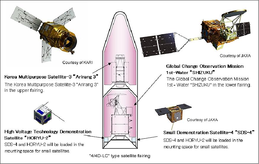
Orbit: Sun-synchronous near-circular orbit, altitude = 685.1 km, inclination = 98.13º , period = 98.5 minutes, LTAN (Local Time on Ascending Node) = 13:30 hours.
Mission Status
• January 2019: The KOMPSAT-3/Arirang-3 mission is fully operational in its 7th year of service. SIIS (SI Imaging Services), a subsidiary of SI (Satrec Initiative), is the exclusive worldwide marketing and sales representative of the KOMPSAT series KOMPSAT-2, KOMPSAT-3, KOMPSAT-3A and KOMPSAT-5. 13)
• The KOMPSAT-3/Arirang-3 mission is operational in January 2017 in its 5th year on orbit. 14)
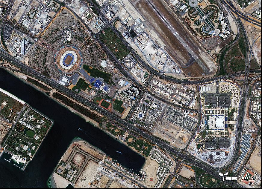
• The KOMPSAT-3 spacecraft and its payload are operating nominally in 2016. 15)
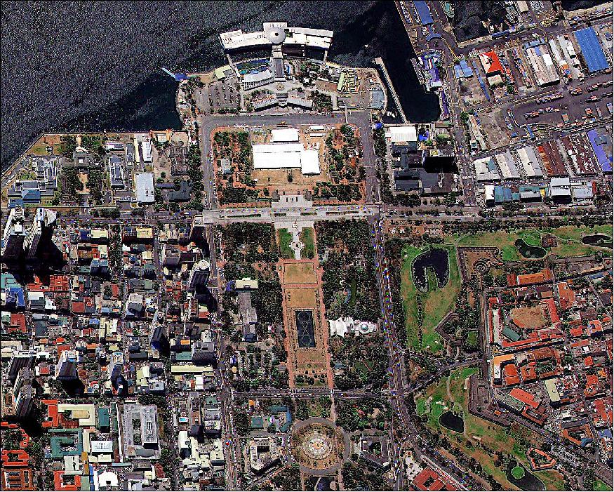
• SIIS released the image of Figure 6 on Dec. 14, 2015 showing a portion of Manila, the capital of the Philippines. 16)
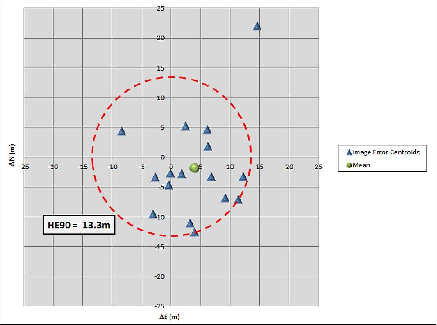
• May 2015: The U.S. NGA (National Geospatial-Intelligence Agency) provided an absolute geolocation accuracy evaluation for KOMPSAT-3 using 25 KOMPSAT-3 images provided by SI (Satrec-Initiative Co. Ltd.), Daejeon, Korea. The outcome is as follows: 17)
Test site | Image acquisition date | n | Mean ΔE (m) | Mean ΔN (m) | Δr (m) |
Bandari | 26 Dec. 2013 | 15 | 1.8 | -2.8 | 3.3 |
Dobbins | 14 Mar. 2013 | 9 | 3.9 | -12.5 | 13.1 |
Dyess | 20 Jan. 2014 | 17 | 2.4 | 5.2 | 5.8 |
Jomo Kenyatta | 20 Jan. 2013 | 16 | 3.2 | -11.1 | 11.5 |
Karshi Khanabad | 14 Jul. 2014 | 5 | 14.6 | 22.0 | 26.4 |
Kirkuk | 21 Jun. 2014 | 14 | -3.0 | -9.5 | 10.0 |
Marctan | 04 Feb. 2014 | 15 | 6.2 | 1.9 | 6.5 |
Masirah Island | 13 Jul. 2014 | 23 | 11.3 | -7.1 | 13.4 |
Menara | 24 Feb. 2013 | 16 | -8.4 | 4.4 | 9.4 |
Mosul | 26 Jun. 2014 | 7 | 6.2 | 4.6 | 7.7 |
Nellis | 17 Aug. 2014 | 13 | -0.2 | -2.7 | 2.7 |
Ninoy Aquino | 21 Apr. 2014 | 23 | 9.2 | -6.8 | 11.4 |
Riga | 02 Mar. 2013 | 11 | -2.7 | -3.4 | 4.3 |
Seeb | 23 Jul. 2014 | 10 | 12.3 | -3.2 | 12.7 |
Shabaz | 03 Nov. 2014 | 19 | 6.8 | -3.3 | 7.5 |
Sidi Ahmed | 30 May 2013 | 13 | -0.4 | -4.7 | 4.7 |
|
| Mean | 3.9 | -1.8 | 9.4 |
|
| Standard Deviation | 6.2 | 8.3 | 5.8 |
|
| Max | 14.6 | 22.0 | 26.4 |
|
| Min | -8.4 | -12.5 | 2.7 |
The Horizontal Error 90% (HE90) is 13.3 meters.
• The KOMPSAT-3 spacecraft and its payload are operating nominally in 2015. 18)
• The KOMPSAT-3 spacecraft and its payload are operating nominally in 2014. 19)
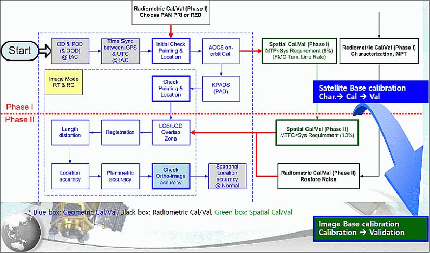
Cal/Val Phase (CVP) | Key item | Requirement value | Validated value | Comments |
| SNR | 100 | >> 100 (TDI 64) |
|
MTF | 8%(PAN) | Across: 8~10% (TDI 64) | Strip imaging | |
GSD | 0.7 m(PAN), 2.8 m(MS) | 0.7 m (PAN) | Strip & Nadir imaging | |
Pointing accuracy | 1.2 km | Across:90 m, Along: 1 sec | Strip imaging | |
Location accuracy | 70 m CE90 | < 70 m CE90 | With POD & PAD, Strip imaging | |
CVP II | MTF after MTFC | 13%(PAN), 19%(MS) | > 20% (PAN) | Level 0 |
Registration | 0.5pixel RMS (MS) | 0.5pixel RMS (MS) | Strip imaging | |
Ortho-image accuracy | 3.5 m CE90 (Horizontal) | 3.5m CE90 (Horizontal) | Strip imaging |
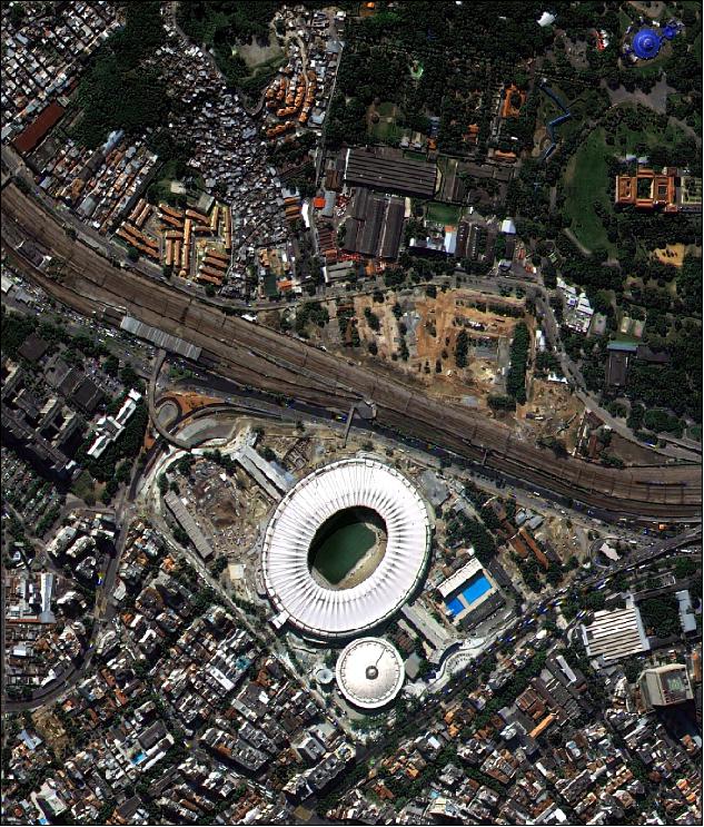
Legend to Figure 9: The Maracanã stadium (official name: Estádio Mário Filho, Maracanã being its neighborhood's name) in Rio de Janeiro (Brazil) is one of the biggest football stadiums in the world, and it is home of the four biggest football teams of Rio: Flamengo, Botafogo, Vasco da Gama and Fluminense.
• In July 2013, ScanEx RDC of Moscow, Russia, became the official distributor of the KOMPSAT data series in Russia and the CIS countries (Ukraine, Belarus, Moldova, Kazakhstan, Uzbekistan, Kyrgyzstan, Turkmenistan, Armenia and Azerbaijan), following the signing of an agreement with the Korean company Satrec Initiative Co., Ltd. 23)
• As of May 17, 2013, KOMPSAT-3 is 1 year on orbit. For the first year of operation, the performance of KOMPSAT-3 was validated, and the worldwide commercial service of KOMPSAT-3 imagery was started by SI (Satrec Initiative), since April 1, 2013. 24) 25)
- KOMPSAT-3 can provide sub-meter images with various imaging modes including single pass stereo. It will continue to provide sub-meter imagery to domestic and international users for the applications of public safety, resource management, environmental monitoring, location-based services, intelligence and disaster monitoring.
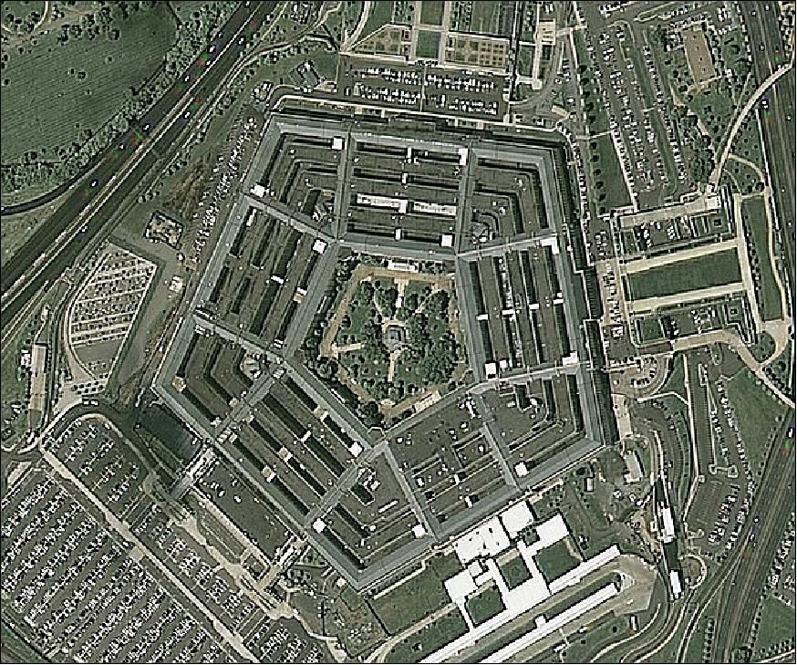
• April 8, 2013: KARI (Korea Aerospace Research Institute) has announced the start of commercial services of KOMPSAT-3 after in-orbit validation on 29 March, 2013. Now, Satrec Initiative will distribute KOMPSAT-3 imagey on a world-wide basis. KOMPSAT-3 provides 0.7m panchromatic and 2.8m multispectral imagery. KOMPSAT-3 has a unique local access time of 13:30 hours, and the imaging capability in the afternoon will increase the chance of acquiring cloud-free images over specific targets for the end users. 26)
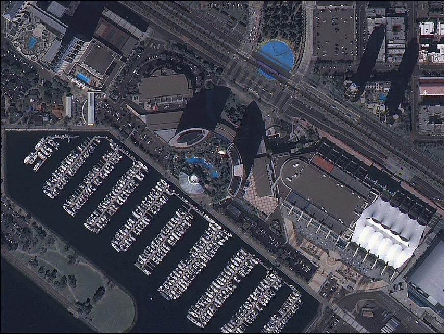
• In January 2013, KOMPSAT-3 is still in the commissioning phase and should be operational soon. 27)
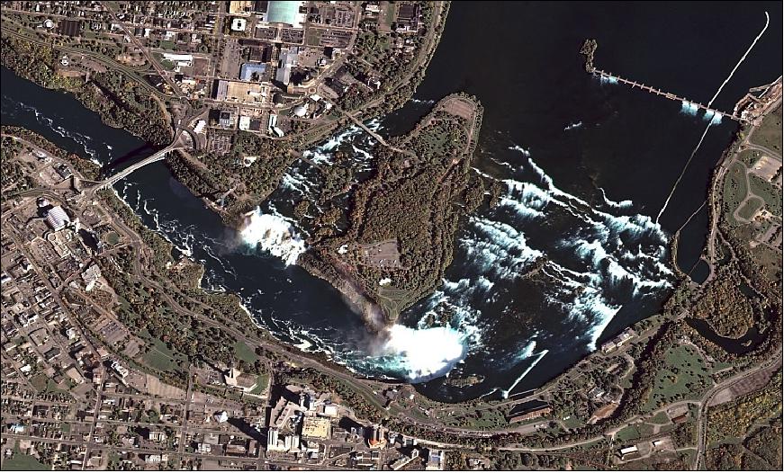
• In November 2012, KARI awarded SI (Satrec Initiative)of Daejeon, Korea a contract as the 'worldwide exclusive representative' for KOMPSAT imagery sales. This applies to imagery of the KOMPSAT-2, -3 and -5 missions. KARI has chosen Satrec Initiative for its ability to develop international customers and data distribution network, as well as long experience in space industry. Satrec Initiative will deliver high quality image data to worldwide customers through collaboration with existing satellite operators, and in addition to that, building its own KOMPSAT data distribution network. 28)
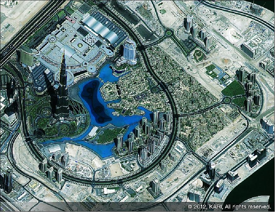
Legend to Figure 13: With 829.8 m, the Burj Tower is he tallest man-made structure in the world. The building officially opened on January 4, 2010.
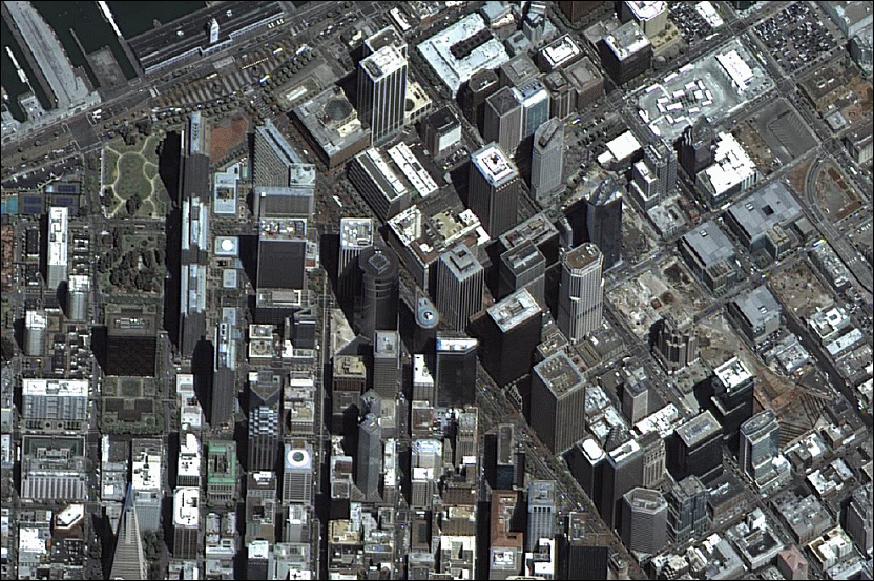
• On June 15, 2012, KARI released the first image obtained by KOMPSAT-3 (Figure 15). A check-up of the condition, attitude control systems, and on-board equipment has confirmed that the KOMPSAT-3 is functioning normally. KOMPSAT-3 will be scheduled to start its full operation in September after further inspection of the satellite and its payloads. 29)
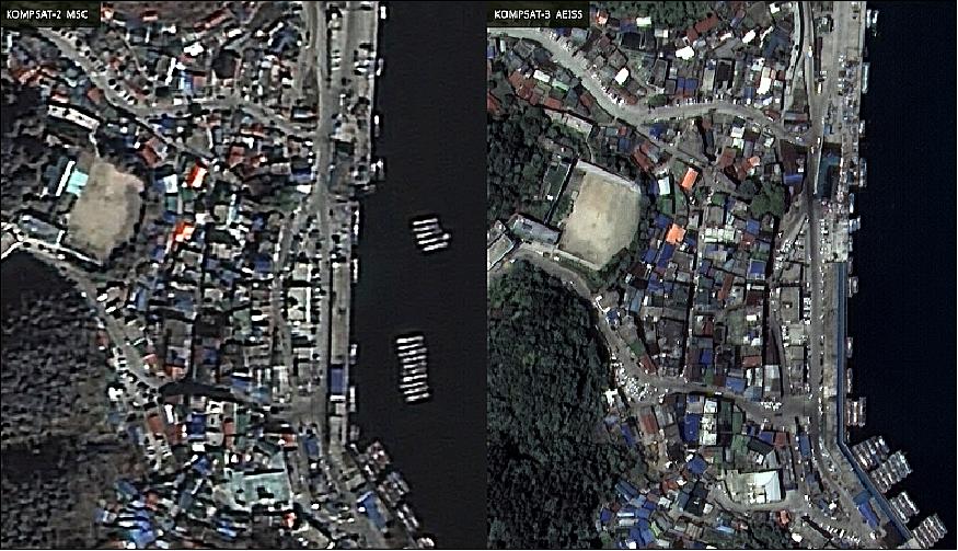
Legend to Figure 15: The image scene is of Jeodong Port on Ulleungdo Island, Korea. The KOMPSAT-3 image (right) clearly shows the roofs of the buildings, cars on the road, and the ships and tide breakers along the shore.
• After the separation of KOMPSAT-3 spacecraft at 16 minutes into the flight, the GCOM-W1 spacecraft separated from the launch vehicle 23 minutes after launch (Ref. 12).
Some background on the KOMPSAT imagery distribution: In November 2012, Satrec Initiative (SI) of Daejeon, Korea announced an agreement with KARI (Korea Aerospace Research Institute) for "Worldwide Marketing and Sales Representative of KOMPSAT-2, -3, -3A and -5 image data." KARI assigned Satrec Initiative as the ‘worldwide exclusive representative' for KOMPSAT imagery sales. 30)
In response, the SI (Satrec Initiative Group) started a new company, SIIS (SI Imaging Services).The SIIS facilities are located at KARI. SIIS is the satellite imagery provider for Remote Sensing and Earth Observation. SIIS is the exclusive worldwide marketing and sales representative of the KOMPSAT series which is KOMPSAT-2, -3, -3A, -5 and DubaiSat-2. The DubaiSat-2 spacecraft was developed by SI in cooperation with MBRSC (Mohammed Bin Rashid Space Center), Dubai, UAE (United Arib Emirates), formerly EIAST (Emirates Institution for Advanced Science and Technology). On April 18, 2015, EIAST was officially renamed to MBRSC. 31)
Sensor Complement
AEISS (Advanced Earth Imaging Sensor System)
AEISS is a high-resolution pushbroom imager (Pan and MS) for land applications of cartography and disaster monitoring. The prime instrument of the mission is being developed by KARI with technical support from EADS Astrium GmbH, Friedrichshafen. In turn, DLR was subcontracted by Astrium for the development of the FPA (Focal Plane Assembly) and CEU (Camera Electronics Unit). 32) 33) 34) 35)
There are two major subsystems to AEISS: EOS and the OM (Optical Module) with the telescope.
EOS (Electro-Optical Subsystem)
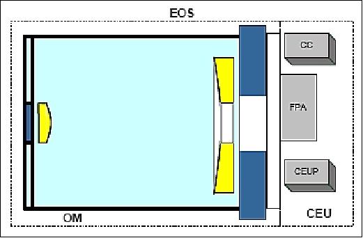
The EOS architecture of AEISS is comprised of the following modules: OM (Optical Module) and CEU which in turn consists of the CEUP (CEU Power supply), CC (Camera Controller), and FPA (Figure 16). The CEUP and CC modules are actually part of the spacecraft bus, while the FPA is integrated with OM to constitute EOS.
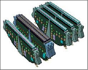
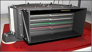
The FPA design features a modular and scalable architecture; it has a total of six independent FPMs (Focal Plane Modules) in a stacking configuration, 2 are dedicated for the Pan bands and 4 are used for the MS bands. One Pan module operates as primary while and the other is used as a cold redundant module. Each FPM consists of a CCD module and spectral filters and FPE (Focal Plane Electronics).
EOS features also a focus mechanism for the best focusing and combined active/passive thermal control mechanism to take images at the best temperature condition. The focusing control is performed using the displacement of the heater ring attached on the upper and lower side of the telescope by heating one of two rings, thereby expecting downward or upward movement of the corresponding secondary mirror.
The imagery generated in EOS are transferred to the PDTS (Payload Data Transmission Subsystem) to be downlinked to Ground Station (GS) after compression, encryption, etc.
Spectral bands | 450-900 nm Pan (Panchromatic) |
Optics | - Korsch-type telescope design on a CFRP optical bench |
GSD (Ground Sample Distance) | - 0.7 m for Pan band at nadir |
Swath width | 15 km (at nadir) |
Tilt angle | Roll: ±45º, pitch: ±30º |
Location accuracy | < 48.5 m CE90 |
Pan CCD detector module | - Line array of 24,000 pixels consisting of 2 stacks of 12 k pixels each |
MS CCD detector module | - Line array of 6,000 pixels, provision of 8 stacks, TDI capability |
Antiblooming | Yes |
PRNU (Photo Response Non-Uniformity) | Yes |
DSNU (Dark Signal Non-Uniformity) | Yes |
SNR (Signal-to-Noise Ratio) | > 100 for Pan and MS |
Data quantization | 14 bit |
Data compression | CCSDS 120.1-G-1E |
Payload data memory | 512 Gbit |
Data rate | 1 GB/s |
Instrument mass, power | ??? |
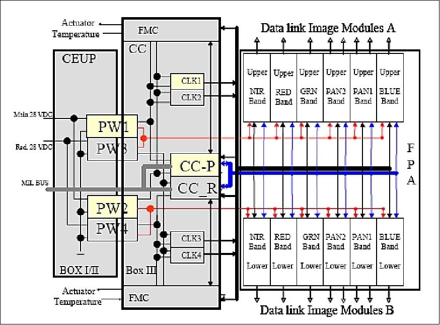
CEU (Camera Electronics Unit): The CEU manages the overall operation of EOS; hence, it defines the functionality and operational capabilities of EOS which implies also the performance of the FPA. The CEU architecture is shown in Figure 19. The CC (Camera Control) unit of CEU communicates with the spacecraft OBC via a MIL-STD-1553B interface.
Optical Design of the Korsch-Type Telescope
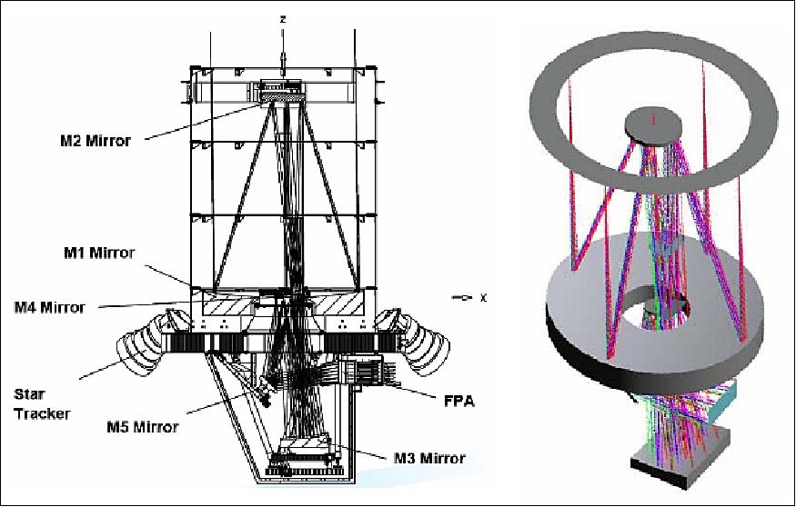
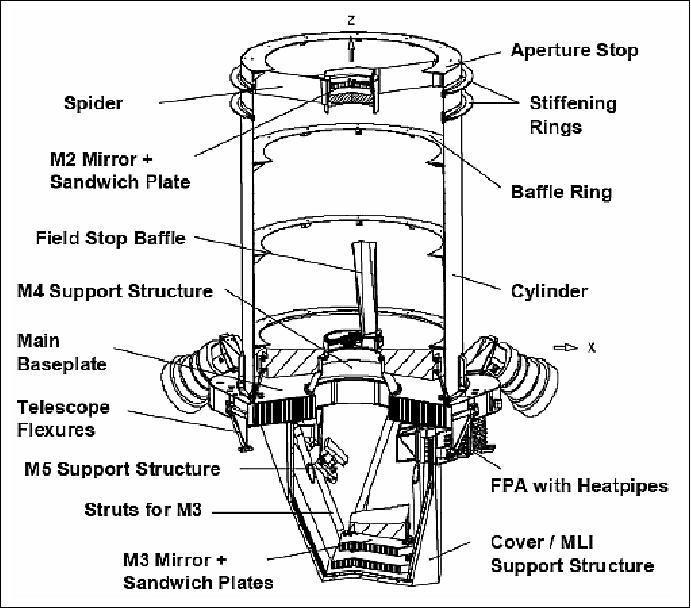
The large telescope of AEISS features a CFRP (Carbon Fiber Reinforced Plastic) envelope material to achieve the required low-mass structure with high stiffness and dimensional stability. Throughout the launch phase and under variable on-orbit conditions, the instrument has to keep the following optical elements in place within tolerances of a few µm and µrad (Table 6): 5 mirrors, the FPA (Focal Plane Assembly) with 1 panchromatic and 4 multispectral bands, and two Star Trackers.
The development, manufacturing and testing under various load conditions (including thermal cycling) of the HSTS (High Stability Telescope Structure) was done and verified by EADS Astrium. 37)
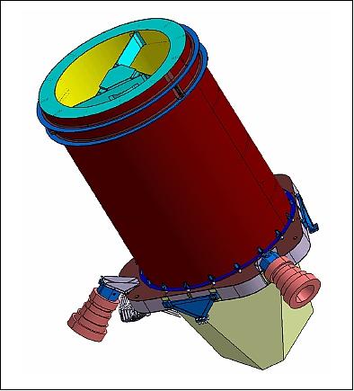
Envelope of structure | < Ø 1.3 m x 2.1 m |
Mass of camera structure | < 80 kg |
First natural frequency | > 70 Hz |
Design load (quasi static) | 15 g per axis |
In-orbit environmental temperatures | -10ºC ~ +45ºC |
Qualification temperatures | -15ºC ~ +55ºC |
SESO (Société Européenne de Systèmes Optiques) of Aix en Provence, France was awarded a subcontract for the manufacturing of the whole set of telescope mirrors (5 mirrors, 2 flight models). SESO activities did also include the mechanical design, manufacturing and mounting of the attachment flexures between the mirrors, the integration on the CFRP (Carbon Fiber Reinforced Plastics) baseplates, and the environment tests of the 5 mirrors. 38)
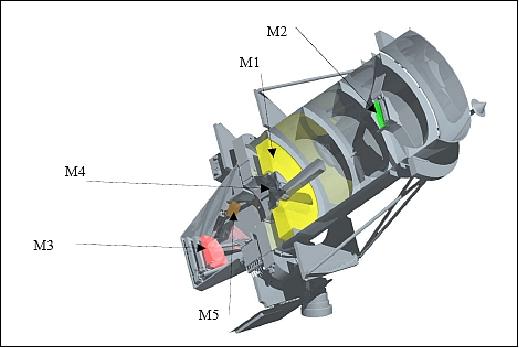
The optical design features a Korsch-type telescope with 5 mirrors, as presented in Figure 21. It includes:
• An on-axis Cassegrain telescope with a primary mirror (M1 concave) and a secondary mirror (M2 convex)
• A tertiary off-axis mirror (M3 concave off-axis)
• An on-axis M4 aspherical concave mirror
• A folding flat mirror (M5), for reasons of overall volume limitations.
Optical element | Parameter | Accuracy requirement |
M1 (Mirror 1) | Distance to M2 | 3 µm |
M2 | Distance to M3 | 10 µm |
M3 | Distance to M4 | 10 µm |
M4 | Distance to Focal Plane | 10 µm |
M5 | Distance to Focal Plane | 10 µm |
Star Tracker | Tilt | 87 µrad |
The use of CFRP, especially the selection of UHM (Ultra High Modulus) carbon fiber compounds, offer the possibility to build up laminates with CTE (Coefficient of Thermal Expansion) characteristics close to zero or even with a negative CTE. A CTE of zero fits well with mirrors made of Zerodur, so that the telescope becomes insensitive not only against temperature changes, but also against temperature gradients.
AEISS pre-flight calibration: A LUIS (Large Uniform Light Source) was used for the electro-optical tests of the payload such as signal to noise ratio, linearity, saturation and uniformity of radiometric response. The uniform light source provides known radiance levels with absolute accuracy traceable to the NIST (National Institute of Standards and Technologies) or equivalent primary standards of radiance scale. 39)
Parameter / Mission | KOMPSAT-1 | KOMPSAT-2 | KOMPSAT-3 | KOMPSAT-5 |
Launch date | Dec. 20, 1999 | July 28, 2006 | May 17, 2012 | August 22, 2013 |
Main payload | EOC (Electro Optical Camera) | MSC (Multispectral Camera) | AEISS (Advanced Earth Imaging Sensor System) | COSI (Corea SAR Instrument), X-band |
Resolution/swath width | 6.6 m (Pan) | 1 m (Pan) / 15 km | 0.7 m (Pan) / 16.8 km | 1 m / 5 km |
Orbital altitude | 685 km | 685 km | 685 km | 550 km |
LTAN | 10:50 hours | 10:50 hours | 13:30 hours | 6:00 hours |
Spacecraft design life | 3 years | 3 years | 4 years | 5 years |
Spacecraft mass | 470 kg | 770 kg | 980 kg | 1400 kg |
Spacecraft power | 636 W | 1.0 kW | 1.3 kW | 1.4 kW |

Ground Segment
The ground segment at KARI site comprises two elements:
1) MCE (Mission and Control Element). The MCE provides the mission planning and satellite command, control functions that allow the operators to perform the mission, and maintain the health of the satellite. The MCE provides the S-band command and telemetry communications interface to the satellite and the necessary functions to operate the satellite.
2) IRPE (Image Reception and Processing Element). The IRPE provides the capability to receive and store KOMPSAT-3 data, support to collection planning, generate standard and value added imagery products, and distribute imagery products to users. The IRPE provides the X-band reception interface from the satellite.
SI developed the IRPS (Image Reception and Processing Station). The IRPS consists of four subsystems;
• UIS (User Interface Subsystem)
• ICPS (Image Collection Planning Subsystem)
• DIS (Direct Ingestion Subsystem)
• PMS (Product Management Subsystem).
The UIS is to process ‘Product Order' of the External User. It virtualizes a convenient operator interface to manage orders from the end-users and the end-user interface such as catalog searching, order placing, order status monitoring and product download.
References
1) http://new.kari.re.kr/english/02_cms/cms_view.asp?iMenu_seq=111
2) "KOMPSAT-3 (Korea Multi-Purpose Satellite-3) Project," KARI, URL: http://www.kari.re.kr/data/eng/contents/Space_
002.asp?catcode=1010111100&depthno=0
3) "The Status of Space R&D and Commercialization Activities in Korea," Aug. 26, 2010, URL: http://www.bsxindia.com/GwanghyeokJU.pdf
4) http://www.satreci.com/eng/ds1_1.html?tno=5 [web source no longer available]
5) "KOMPSAT-3," URL: http://www.satreci.com/eng/ds1_1.html?tno=5#a76 [web source no longer available]
6) "KOMPSAT-3 Solar Array Deployment Mechanism," SpaceTech, URL: http://www.spacetech-i.com/K-3-SA-deployment-mechanism.html
7) "Launch Result of the Global Changing Observation Mission 1st - Water "SHIZUKU" (GCOM-W1) and the Korean Multi-purpose Satellite 3 (KOMPSAT-3) by H-IIA Launch Vehicle No. 21," JAXA, May 18, 2012, URL: http://www.jaxa.jp/press/2012/05/20120518_h2af21_e.html
8) "JAXA H-2A launches SHIZUKU and Arirang 3 from Tanegashima," May 17, 2012, URL: http://www.nasaspaceflight.com/2012/05/jaxa-h
-2a-launches-shizuku-arirang-3-tanegashima/
9) http://h2a.mhi.co.jp/en/f21/overview/index.html
10) "Japan To Launch Korean Spysat In First Foreign Contract," SpaceMart, Jan. 14, 2009, URL: http://www.spacemart.com/reports/Japan_To_Launch
_Korean_Spysat_In_First_Foreign_Contract_999.html
11) "Launch Overview," MHI (Mitsubishi Heavy Industries), URL: http://h2a.mhi.co.jp/en/f21/overview/index.html
12) "Shizuku Special Site," JAXA, URL: http://www.jaxa.jp/countdown/f21/overview/h2a_e.html
13) Information provided by Sungdong Park, Chairman, Satrec Initiative Co., Ltd., Daejeon, Korea.
14) Information provided by Moongyu Kim, President & CEO of SIIS (SI Imaging Services), Daejeon, Korea
15) Information provided by Daewon Chung, the head of the KARI Ground Systems Development Department, Daejeon, Korea.
16) "KOMPSAT-3 image of Manila," SIIS, Dec. 14, 2015, URL: http://www.si-imaging.com/ds4_1_1.html?db=gal_bbs2
&no=199&c=view&page=1&SK=&SN=&idx=[web source no longer available]
17) Paul Bresnahan, Evan Brown, Luis Henry Vazquez, "KOMPSAT-3 Absolute Geolocation Accuracy Evaluation," JACIE (Joint Agency Commercial Imagery Evaluation)Workshop , Tampa, FL, USA, May 4-8, 2015, URL: https://calval.cr.usgs.gov/wordpress/wp-content/
uploads/15-348-Kompsat-3-Absolute-Geolocation
-Accuracy-Evaluation-JACIE2015.pdf
18) Information provided by Sungdong Park, CEO & Managing Director of SI (Satrec Initiative Co. Ltd.), Daejeon, Korea.
19) "KOMPSAT Imagery, benefits to our community," SIIS (SI Imaing Services), April 14, 2014, URL: https://www.gisworx.ae/geomatica/downloads/
KOMPSAT%20Imagery,%20benefits%20to%20our
%20community_v1.0.pdf [web source no longer available]
20) DongHan Lee, DooChunSeo, HeeSeobKim, EungSikLee, HaeJinChoi, "Calibration and Validationfor KOMPSAT-3," Proceedings of JACIE 2014 (Joint Agency Commercial Imagery Evaluation) Workshop, Louisville, Kentucky, March 26-28, 2014, URL: https://calval.cr.usgs.gov/wordpress/wp
-content/uploads/14.027_KOMPSAT3_CalVal.pdf
21) DooChun Seo, DongHanLee, SunGuLee, HyoSukLim, "Overview of KOMPSAT-3 Geometric Calibration & Accuracy," Proceedings of JACIE 2014 (Joint Agency Commercial Imagery Evaluation) Workshop, Louisville, Kentucky, March 26-28, 2014, URL: https://calval.cr.usgs.gov/wordpress/wp-content/uploads/
14.035_2014_JACIE_K3Geo_DooChun_1.pdf
22) "KOMPSAT-3 image, released by SI on Jan. 03, 2014, " URL: http://kompsat.satreci.com/ds4_2_1.html?db=gal
_bbs2&no=69&c=view&page=1&SK=&SN=&idx=
23) "ScanEx RDC became the official distributor of KOMPSAT data," ScanEx RDC, July 16, 2013, URL: http://press.scanex.ru/index.php/en/news/item/4018-kompsat
24) "One Year Anniversary of KOMPSAT-3 Launch," Space Mart, May 30, 2013, URL: http://www.spacemart.com/reports/One_Year_
Anniversary_of_KOMPSAT_3_Launch_999.html
25) "Satrec Initiative... The First Year Anniversary For KOMPSAT-3 Is Also A Pricing Benefit (Imagery)," Satnews Daily, May 17, 2013, URL: http://www.satnews.com/story.php?number=1233155485#
26) "Commercial sales of KOMPSAT-3 has started," Satrec Initiative, April 8, 2013, URL: [web source no longer available]
27) Bang-Yeop Kim, "The practical uses and application status of satellite image in Korea," Proceedings of the 50th Session of Scientific & Technical Subcommittee of UN-COPUOS, Vienna, Austria, Feb. 11-22, 2013, URL: http://www.oosa.unvienna.org/pdf/pres/stsc2013/tech-15E.pdf
28) "Satrec Initiative Announces Agreement with Korea Aerospace Research Institute," Satrec Initiative, Nov. 15, 2012, URL: https://www.spacedaily.com/reports/Satrec_Initiative_Announces_Agreement_with_Korea_Aerospace_Research_Institute_999.html
29) http://m.kari.re.kr/kor/html/news/news_view.html
?num=1518¤tPage=1&searchType=&searchString=
30) "Satrec Initiative Announces Agreement with Korea Aerospace Research Institute," SI, Nov. 15, 2012, URL: http://www.satreci.com/eng/ds1_1.html?tno=100&db=pr_board&no=22
31) https://web.archive.org/web/20160918150636/http://www.si-imaging.com/ds1_1_1.html
32) Andreas Eckardt, Anko Börner, Stefan Hilbert, Ingo Walter, "High resolution Instruments for Air-and Spaceborne Application," DLR, DIN-WS, Nov. 20, 2006, URL: http://www2.informatik.hu-berlin.de/cv/documents/Fusion_Workshop_11.2006/02_Eckardt.pdf
33) Jong-Pil Kong, Andreas Eckardt, Bo-Gwan Kim, "The Design of the Focal Plane Assembly for AEISS," Proceedings of the 60th IAC (International Astronautical Congress), Daejeon, Korea, Oct. 12-16, 2009, IAC-09.B1.I.6
34) "KOMPSAT-3 Image Data Manual," KARI, Satrec Initiative, V1.0/ 2013.04.01, URL: https://web.archive.org/web/20140227125127/http://www.geosoluciones.cl/documentos/Kompsat/KOMPSAT3_Image_Data_Manual_v1.0.pdf
35) KOMPSAT-3 Submeter in the afternoon," SI, URL: http://kompsat.satreci.com/ds2_3_1.html
36) http://www.dlr.de/os/en/desktopdefault.
aspx/tabid-7311/12268_read-29159/
37) Deog-Gyu Lee, Eung-Shik Lee, Su-Young Chang, Andreas Kasemann, Dietmar Scheulen, Tom Butters, "The development of a dimensionally stable CFRP camera structure," Proceedings of the 60th IAC (International Astronautical Congress), Daejeon, Korea, Oct. 12-16, 2009, IAC-09.C2.2.1
38) Hélène Ducollet, Christian du Jeu, Seung-Hoon Lee, "Manufacturing of the Spaceborne Camera Mirrors for KARI's LEO Satellite," ICSO 2010 (International Conference on Space Optics), Rhodes Island, Greece, Oct. 4-8, 2010
39) Vikrant Mahajan, Dae-Jun Jung,, "Design and Characterization of Uniform Spectral Radiance source for test and calibration of radiometers used for KOPMSAT-3," SPIE Proceedings Volume 6958, 'Sensors and Systems for Space Applications II,' Editors: Richard T. Howard, Pejmun Motaghedi, May 2008, URL: https://www.researchgate.net/publication/252498267_Design_and_characterization_of_uniform_spectral_radiance_source_for_test_and_calibration_of_radiometers_used_for_KOPMSAT-3
40) Sang-Ryool Lee, Joo-Jin Lee, "The History of the Korea Multi-Purpose Satellite Program," Proceedings of the 60th IAC (International Astronautical Congress), Daejeon, Korea, Oct. 12-16, 2009, IAC-09.E4.3.3
The information compiled and edited in this article was provided by Herbert J. Kramer from his documentation of: "Observation of the Earth and Its Environment: Survey of Missions and Sensors" (Springer Verlag) as well as many other sources after the publication of the 4th edition in 2002. - Comments and corrections to this article are always welcome for further updates (eoportal@symbios.space).
Spacecraft Launch Mission Status Sensor Complement Ground Segment References Back to top