KOMPSAT-3A (Korea Multi-Purpose Satellite-3A) / Arirang-3A
EO
High resolution optical imagers
Land
Multi-purpose imagery (land)
Launched in March 2015, KOMPSAT-3A (Korea Multipurpose Satellite-3A) is a collaborative mission between the Korea Aerospace Research Institute (KARI), a Korean Government organisation, and two commercial entities, KAI (Korea Aerospace Industries) and APA (Asia-Pacific Aerospace). The mission aims to collect infrared (IR) and high resolution electro-optical imagery for Geographical Information Systems (GIS) applications, and is the successor to KOMPSAT-3.
Quick facts
Overview
| Mission type | EO |
| Agency | KARI |
| Mission status | Operational (extended) |
| Launch date | 26 Mar 2015 |
| Measurement domain | Land |
| Measurement category | Multi-purpose imagery (land), Vegetation, Landscape topography |
| Measurement detailed | Land surface imagery, Vegetation type, Land surface topography |
| Instruments | AEISS-A |
| Instrument type | High resolution optical imagers |
| CEOS EO Handbook | See KOMPSAT-3A (Korea Multi-Purpose Satellite-3A) / Arirang-3A summary |
Summary
Mission Capabilities
There are two sensors onboard KOMPSAT-3A:
- the AEISS-A (Advanced Electronic Image Scanning System-A) high-resolution optical imager,
- IIP (Infrared Imaging Payload), an MWIR (Medium-wave Infrared) single-channel imager.
AEISS-A images in two channels; one panchromatic (PAN) channel and one multispectral (MS) channel. It aims to capture high spatial resolution imagery of land and vegetation, highly applicable in environmental and agricultural sciences in terms of biomass and land cover analysis, as well as monitoring natural disasters.
The IIP sensor module aims to capture geospatial, environmental and agricultural information, with additional applications in the monitoring of forest fires, volcanic activity and other natural disasters.
Performance Specifications
AESSI-A operates in five spectral bands across both channels: a single PAN band and four MS bands (blue, green, red and NIR(Near Infrared)), with a spectral range of 450-900 nm across the four MS bands, and the same range for the PAN band.
The imager has GSD (Ground Sample Distance) at nadir of 0.55 m for PAN imaging and 2.2 m for MS imaging, with a 12 km swath width. Across its 5 bands, it has a maximum spatial resolution of 0.7 m (PAN).
The IIP sensor operates within the MWIR region of 3 - 5 µm, at a spatial resolution of 5.5 m and a swath width of 12 km.
KOMPSAT-3A operates in a sun-synchronous orbit at an altitude of 528 km and with an inclination of 97.5°. It has an LTAN (Local Time on Ascending Node) of 1330 hours, with a period of 98.5 minutes and repeats the cycle of 28 days.
Space and Hardware Components
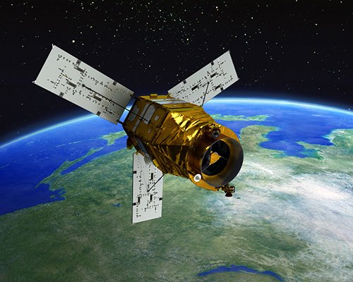
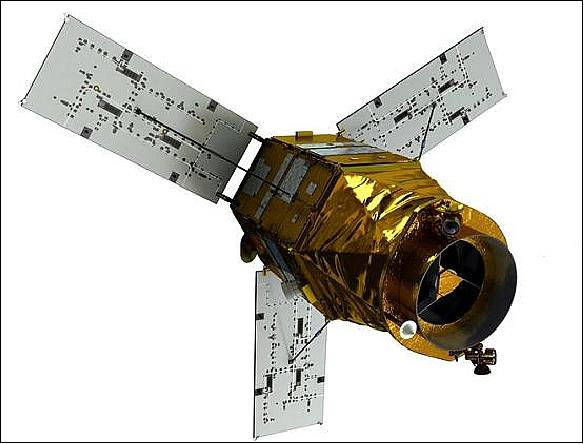
The spacecraft bus used by KOMPSAT-3A is identical to its sister satellite, KOMPSAT-3, and was designed specifically for these missions, featuring a hexagonal platform and a cylindrical nadir module hosting the optical payload systems.
The bus contains a Propulsion Module, an Equipment Module and the Nadir Module, with dimensions 2.0 m (diameter) x 3.5 m (height) and launches mass of 1100 kg. The ADCS (Attitude Determination and Control Subsystem) is equipped with a series of coarse sun sensors, an IMU (Inertial Measurement Unit) and star trackers as attitude determination sensors, with reaction wheels as attitude actuators. This ADCS can achieve pointing accuracy of 0.025°, and supports quick slew manoeuvres up to ±45° off-nadir. KOMPSAT-3A uses an S-band system for TT&C (Tracking, Telemetry and Command) communications and a high-speed, 1Gbit/s X-band system for imagery downlink from the solid-state memory module.
KOMPSAT-3A had an expected design life of 4 years, which it has outlasted, being still operational as of July 2022.
KOMPSAT-3A (Korea Multi-Purpose Satellite-3A) / Arirang-3A
Spacecraft Launch Mission Status Sensor Complement References
KOMPSAT-3A is Korea's first Earth observation/Infrared satellite with two imaging systems on board. The main goal of the KOMPSAT-3A program of KARI (Korea Aerospace Research Institute) is to develop an Earth observation satellite to obtain IR (Infrared) and high-resolution EO (Electro-Optical) images for GIS (Geographical Information Systems) applications in environmental, agricultural and oceanographic sciences as well as natural disasters.
A prime example of cooperation between the government and private sector to commercialize space technologies is the current KOMPSAT-3A project. KARI designed and built KOMPSAT-3, an Earth observation satellite that was launched in May 2012 from Japan's Tanegashima Space Center. Now KARI is assisting Korea Aerospace Industries (KAI) and Asia-Pacific Aerospace build the KOMPSAT-3A, a near replica of the KOMPSAT-3, in an exercise that will transfer technologies to these firms and enable them to enter the satellite supplier market. The Ministry of Science, ICT and Future Planning (MSIP) is tasked by the president to conduct studies and to develop strategies for the commercialization of the space sector, but the ministry delegates most of the actual work to KARI for subsequent review by the MSIP's Space Policy Division. The MSIP has commissioned KARI's Policy and International Cooperation Division to conduct an ongoing study on the commercialization of space technologies. 1)
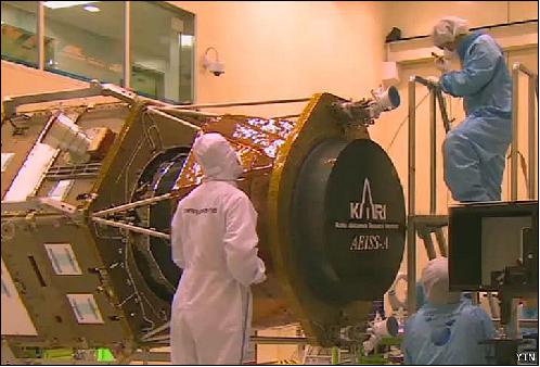
Spacecraft
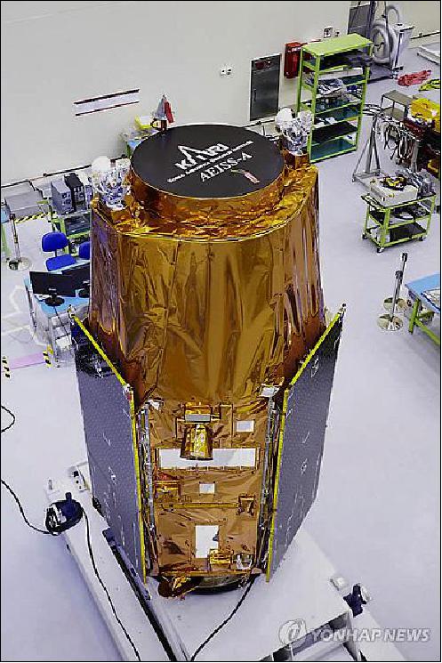
The spacecraft is being built at KAI (Korea Aerospace Industries, Ltd.) with HQs at Sacheon, Korea. The KOMPSAT-3A satellite carries an optical imaging system sensitive to wavelengths in the visible and infrared range, building on the KOMPSAT-2 and -3 satellites that carried similar payloads.
KOMPSAT-3A is the sister of KOMPSAT-3, using an identical satellite bus and payload with the only difference being an added infrared capability via beamsplitter and relay optics. The satellite will expand the existing constellation and ensure data continuity after KOMPSAT-3 reaches its planned EOL (End-of-Life) date after three to five years of operation. The main purpose of the optical KOMPSAT spacecraft is to deliver high-resolution imagery for Geographical Information Systems as well as environmental, agricultural and oceanographic monitoring.
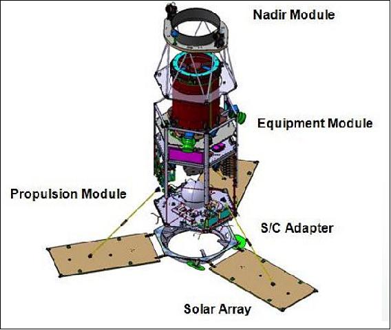
The satellite bus consists of a hexagonal platform and a cylindrical nadir module hosting the optical payload systems. Beginning in the aft, the satellite consists of a Spacecraft Adapter interfacing with the launcher, a Propulsion Module, an Equipment Module and the Nadir Module. The satellite has a mass of just under 1,100 kg measures 2.0 m in diameter and stands 3.5 m tall. The design life is 4 years.
ADCS (Attitude Determination and Control Subsystem)
The spacecraft is equipped with three different attitude sensors - a series of coarse sun sensors, an IMU (Inertial Measurement Unit) and star trackers. The coarse sun sensors provide a basic sun vector direction to be used in the event of a spacecraft safe mode to keep the solar panels pointed to the sun to ensure good power generation. The star trackers use optical imaging heads and electronics units to capture imagery of the star-filled sky using a narrow field of view. The stars in that field of view are compared to a catalogue of known star constellations from which the three-axis orientation of the satellite can be determined to provide very precise pointing information. Inertial measurement data is used to measure body rates used to reduce spacecraft motion to allow the star trackers to acquire star patterns which require low body rates on the satellite.
Attitude actuation is provided by reaction wheels. The reaction wheel assembly represents a rotating mass that is driven by a motor – when accelerating or decelerating the wheel, the satellite body will move in the opposite direction as the result of induced counter torque. To allow de-spins of the wheels, the satellite uses magnetic torquers that use the Earth's magnetic field to create a force that counters that of the de-spinning wheel to desaturate the reaction wheels at regular intervals. The agile attitude control system achieves a pointing accuracy of 0.025º and can support quick slew manoeuvres up to ±45 º off nadir. This satellite agility permits event monitoring. Position and velocity measurements are provided by a GPS unit.
EPS (Electrical Power Subsystem):
Provision of 1.4 kW with three deployable solar panels.
Orbit corrections and maintenance are supported by a hydrazine propulsion system that consists of a central hydrazine tank, a pressurization system and two thruster banks of four 4.5 N thrusters. The thrusters use the catalytic decomposition of hydrazine monopropellant over a heated catalyst bed to generate thrust.
RF communications:
Use of S-band systems for TT&C communications. A high-speed X-band system (1 Gbit/s) is used to downlink the acquired imagery from a large solid-state memory module.
Launch
The KOMPSAT-3A spacecraft was launched on March 25 2015 (22:08:53 UTC) on a Dnepr-1 vehicle (RS-20) from the Jasny Dombarovsky launch site in Russia. The launch was executed by the Russian Strategic Rocket Forces of the Russian Ministry of Defense with the support of the Russian, Ukrainian and Kazakhstan organizations, which are part of the ISC (International Space Company) Kosmotras industrial team. 2) 3) 4)
Orbit:
Sun-synchronous orbit, altitude = 528 km, inclination = 97.5º, LTAN = 13:30 hours, period = 98.5 minutes, repeat cycle = 28 days.
Mission Status
• January 2019: The KOMPSAT-3A mission is fully operational, producing high-resolution imagery for applications in environmental, agricultural and oceanographic sciences as well as natural disasters. SIIS (SI Imaging Services), a subsidiary of SI (Satrec Initiative), is the exclusive worldwide marketing and sales representative of the KOMPSAT series KOMPSAT-2, KOMPSAT-3, KOMPSAT-3A and KOMPSAT-5. 5)
• December 21, 2017: UrtheCast Corp. of Vancouver, Canada, and its subsidiary, the Earth Observation company Deimos Imaging of Spain, today announced the signing of an agreement with SIIS (SI Imaging Services) of Daejeon, Korea, a leading provider of remote sensing satellite data and exclusive worldwide marketing and sales representative of the KOMPSAT (Korea Multi-Purpose Satellite) program series of KARI (Korea Aerospace Research Institute), for the mutual global distribution of their respective product portfolios. 6) 7) The space assets of Deimos Imaging and SIIS include Deimos-1, Deimos-2 and the KOMPSAT series KOMPSAT-2, KOMPSAT-3, KOMPSAT-3A and KOMPSAT-5, resulting in a wide portfolio of X-band SAR and optical data in a wide range of resolutions, from 22 m to 0.4 m per pixel.
- This is key for a wide range of applications, especially those requiring frequent monitoring over the same area of interest and real-time response, such as emergency services, border and maritime surveillance and defence and security. The assets of SIIS combined with the strategic partners aligned with Deimos Imaging, resulting in a multi-satellite, multi-resolution virtual constellation, to deliver imagery services and geo-analytic applications to customers globally.
• September 29, 2017: SIIS (SI Imaging Services) of Daejeon, Korea is the exclusive worldwide marketing and sales representative of the KOMPSAT series KOMPSAT-2, KOMPSAT-3, KOMPSAT-3A and KOMPSAT-5. SIIS contributes to Remote Sensing and Earth observation industries societies by providing very high-resolution optical and SAR images through over 90 sales partners worldwide. 8) Customers from industries as well as government and international agencies were using KOMPSAT imagery for their missions and research and achieved good results in several remote sensing applications such as mapping, agriculture and disaster management.
• 2017: The KOMPSAT-3A/Arirang-3A spacecraft and its payload are operating nominally in January 2017. 9)
• October 25, 2016: A high-accuracy grid of 21 cm in elevation was verified by PhotoSat for KOMPSAT-3A data. The Canadian Vancouver-based PhotoSat company invented in recent years a new technology, that generates the world's most accurate satellite surveying; the technique specializes in elevation surveying for civil engineering infrastructure projects. PhotoSat had published the survey data processed from the recent 40 cm resolution KOMPSAT-3A satellite; SIIS is in charge of commercial marketing of the KOMPSAT satellite series that KARI (Korea Aerospace Research Institute) has developed and operates. 10) 11)
- For the study, PhotoSat produced a 1m grid of elevations using their proprietary geophysical processing technology with stereo satellite images taken by KOMPSAT-3A. PhotoSat's highly accurate survey grids have been used for years by oil and gas and mining engineers as a cost-effective alternative to ground GPS and airborne LiDAR surveying. The stereo satellite photos from KOMPSAT-3A would enable PhotoSat to deliver engineering-quality survey data everywhere in the world. The 40 cm GSD (Ground Sample Distance) of KOMPSAT-3A data is explained by the fact that SIIS is providing oversampled data products just as Airbus DS does with the Pleiades mission.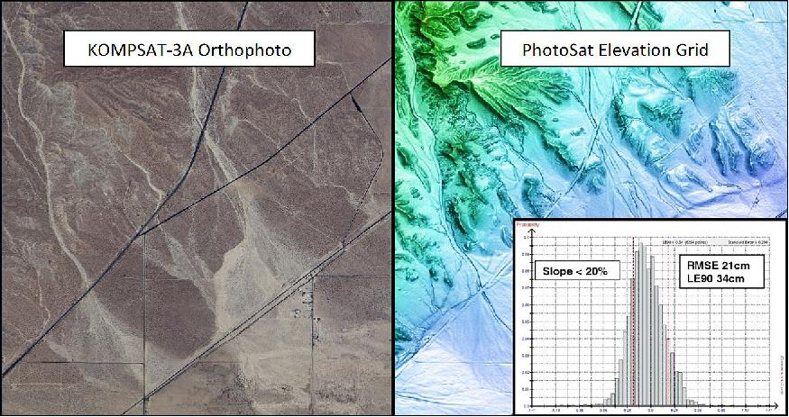
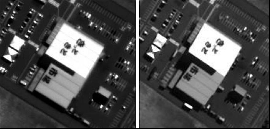
- KOMPSAT-3A is the sister spacecraft of KOMPSAT-3, using the same satellite bus and payload. Its local access time is very unique at 13:30 hours, which is the same as that of KOMPSAT-3. However, since KOMPSAT-3A was put into a lower orbit than KOMPSAT-3 (528 km for KOMPSAT-3A versus 675 km for KOMPSAT-3), it delivers clearer and sharper imagery. The same imaging time and similar payload with KOMPSAT-3 would amplify its capacity and help to even out the difference in colour.
- SIIS (SI Imaging Services) is a leading satellite imagery provider for Remote Sensing and Earth Observation. SIIS is the exclusive worldwide marketing and sales representative of the KOMPSAT constellation, including KOMPSAT-2, KOMPSAT-3, KOMPSAT-3A, and KOMPSAT-5. It is a combination of VHR (Very High Resolution)optical and SAR (Synthetic Aperture Radar) data with variable local access times from the morning to the afternoon (06:00, 10:50, 13:30, 18:00 hours). SIIS provides satellite imagery worldwide through over 80 sales partners.
• 2016: The KOMPSAT-3A spacecraft and its payload were operating nominally. 14)
• October 2015: An optimisation approach was proposed to operate KOMPSAT-3 and KOMPSAT-3A in a more efficient way. For this purpose, the project confirmed communication windows, geometrical characteristics, and contact sequences of the KGS (KARI Ground Station) with KOMPSAT-3A and KOMPSAT-3 during the operation period by using the real orbit data. Also, a mitigation plan was proposed to decrease the possibility of KOMPSAT-3 and KOMPSAT-3A flying over the KGS at the same time. Finally, some issues are removed such as contact overlap time and interference possibilities.15)
• September 2015: The nominal operations phase of the KOMPSAT-3A mission was started after the Cal/Val completion (results below) 16)
Satellite mission | Launch date | Mission altitude | Remark |
KOMPSAT-1 | Dec. 21, 1999 | 685 km SSO | End of mission on Dec. 30, 2007 |
KOMPSAT-2 | July 28, 2006 | 685 km SSO | In operation |
KOMPSAT-3 | May 18, 2012 | 685 km SSO | In operation |
KOMPSAT-5 | Aug. 22, 2013 | 550 km SSO | In operation |
KOMPSAT-3A | Mar. 25, 2015 | 528 km SSO | In operation |
- Table 2 shows the mission orbits of KOMPSAT-3A and KOMPSAT-3. Due to the same LTAN between KOMPSAT-3A and KOMPSAT-3 with different altitudes, the close approach of the two satellites is foreseen. For example, the difference in orbital periods makes the two satellites to be close to each other every second day.
Parameter | KOMPSAT-3A | KOMPSAT-3 |
Payload | EO, IR | EO |
Altitude | 528 km | 625 km |
Inclination | 97.513º | 98.13º |
Mean LTAN (Local Time on Ascending Node) | 13:30 hours | 13:30 hours |
Orbital period | 95.2 minutes | 98.5 minutes |
No of revolutions | 15.1 revolutions/day | 14.6 revolutions/day |
Orbit velocity | 7.60 km/second | 7.51 km/second |
Ground speed | 7.02 km/second | 6.78 km/second |
Repeated ground track | 28days/409revolutions | 28days/423revolutions |
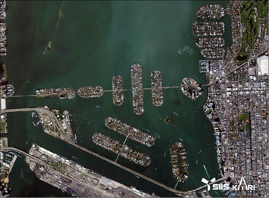
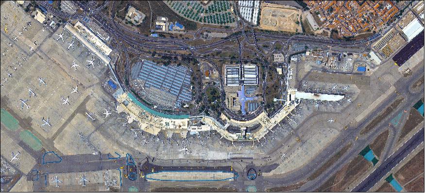
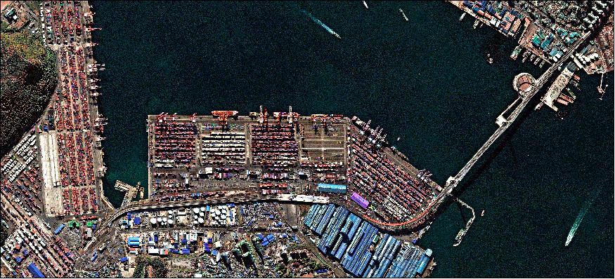
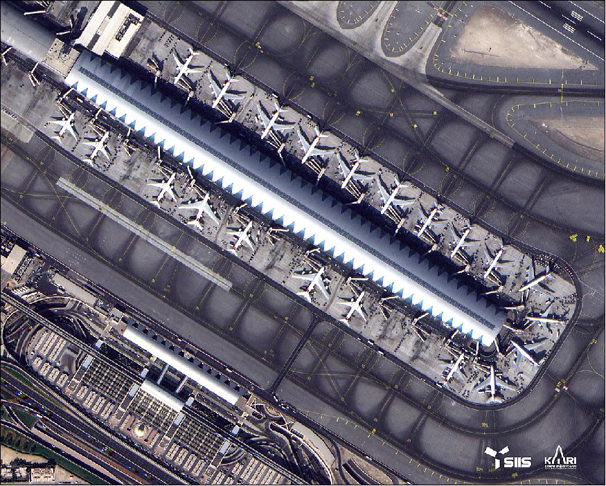
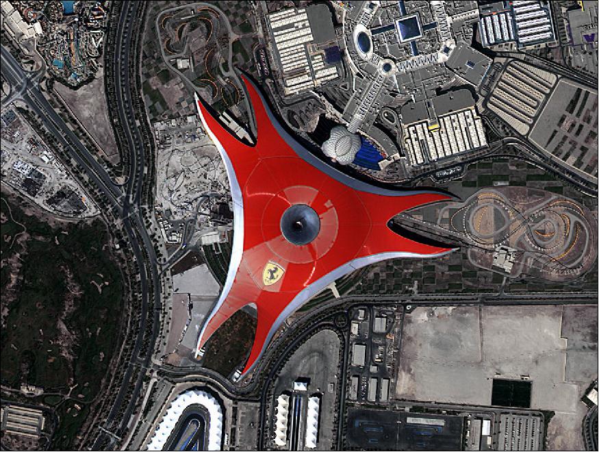
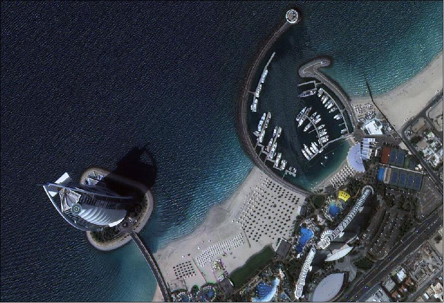
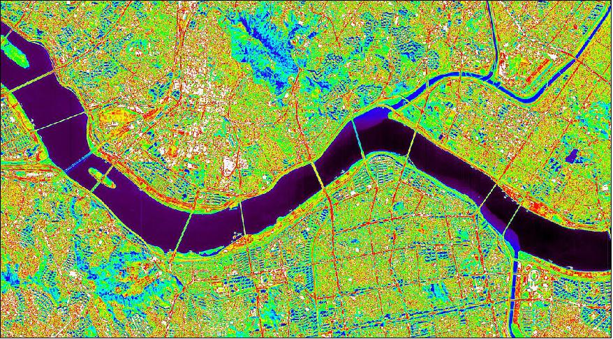
• April 2015: KARI is in the process of providing initial operations of the KOMPSAT-3A mission. 17)The first high-resolution images (55 cm) of KOMPSAT-3A were released on April 1, 2015, showing the Dubai Palm Jumeirah island and the Burj Al Arab hotel area and an infrared image (5.5 m) of the Han River in Korea (the latter two are shown below). 18)
• March 27, 2015: KOMPSAT-3A acquired its first image a day after launch. This was possible because the bus's initial activation and normal mode transition were finished in a day which had been done in three days for previous satellite programs (Ref. 16). The KOMPSAT-3A Earth observation satellite was launched on March 25 2015, and was successfully deployed in orbit and all systems were tested and verified. The KOMPSAT-3A was sent on its way under 15 minutes after liftoff, and deployed into the expected orbit of 528 km altitude, according to Russian press reports. KOMPSAT-3A was programmed to complete its initial steps shortly after separation, deploying its three solar panels, acquiring a stable orientation and switching on its transponders to begin sending data.
• November 2012: The Satrec Initiative (SI) of Daejeon, Korea announced an agreement with KARI (Korea Aerospace Research Institute) for "Worldwide Marketing and Sales Representative of KOMPSAT-2, -3, -3A and -5 image data." KARI assigned Satrec Initiative as the ‘worldwide exclusive representative' for KOMPSAT imagery sales. 19) In response, the SI (Satrec Initiative Group) started a new company, SIIS (SI Imaging Services). The SIIS facilities are located at KARI. SIIS is the satellite imagery provider for Remote Sensing and Earth Observation.
Sensor Complement
The high-resolution electronic optical camera AEISS-A features 55cm class optical photography, which is the highest resolution among cameras mounted on domestic satellites. The IR sensor, which is capable of detecting heat on the ground, is used to observe fires, volcanic activity and urban thermal islands during the day- and nighttime. Arirang-3A operates in the sun's synchronous orbit at an altitude of 528 km and passes over Korea twice (day and night), photographing the Korean Peninsula for up to 50 minutes each day.
AEISS-A (Advanced Earth Imaging Sensor System-A)
The AEISS-A instrument is similar to that of the KOMPSAT-3 spacecraft and was developed by KARI with technical support from Airbus Defence and Space (former EADS Astrium) and DLR (German Aerospace Center) that developed the FPA (Focal Plane Assembly) and the main CEU (Camera Electronics Unit).
AEISS-A consists of an Optical Module and CEU which itself is comprised of:
- a power supply,
- a camera controller
- the FPA (Focal Plane Assembly).
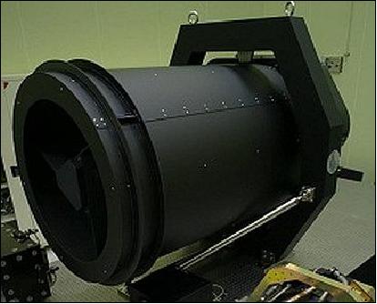
The electronics interface with the onboard computer via a 1553 data bus to exchange commands and housekeeping data. The Optical Module is cylindrical in shape, enclosed in a CFRP (Carbon Fiber Reinforced Plastic) structure that provides high thermal stability and structural stability, which is also provided by support struts to ensure the telescope structure remains in place with tolerances of a few micrometres. The two-star trackers of the spacecraft are installed on the aft segment of the cylindrical optical unit. The optical unit measures 1.3 m x 2.0 m and has a mass of around 80 kg (Ref. 4).
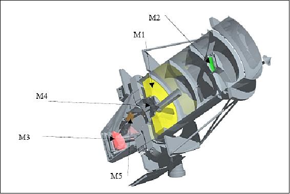
The telescope uses a Korsch combination with three aspheric mirrors and two folding mirrors, using an aperture diameter of 80 cm. This design was chosen because of its simplicity and compact size – fitting within the small spacecraft platform. An entrance baffle is used for stray light rejection. Light entering the instrument passes through a Cassegrain arrangement with an on-axis system of the concave M1 primary mirror and an on-axis convex M2 secondary mirror. The light then passes to an off-axis M3 mirror (concave) reflecting the light to an on-axis M4 aspherical concave mirror passing it on to the M5 folding mirror focusing the radiation onto the FPA. The additional M3 and M4 mirrors create a focal length of 8.6 m.
The telescope mirrors are installed on a CFRP structure while the mirrors themselves consist of Zerodur which provides extremely high thermal stability with low thermal gradients throughout the structure.
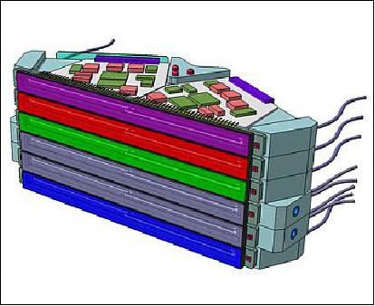
The FPA of the AEISS instrument features a stacked architecture - with two Focal Plane Modules dedicated to the panchromatic band covering a wavelength range of 450 - 900 nm. The two PAN modules are operated in cold redundancy with one module active at a given time. The remaining four Focal Plane Modules are covering the four multispectral channels of AEISS-A:
- blue channel (450-520 nm),
- green (520-600 nm),
- red (630-690 nm)
- and near-infrared (760-900 nm).
The panchromatic line array detector consists of 12,000 pixels per module using a TDI (Time Delay Integration) in four stages creating a raw data rate of 3.84 Gbit/s. The multispectral channels use 6,000-pixel line array detectors with TDI employing pixel binning and delivering data at 240 Mbit/s per channel. The optical payload uses anti-blooming techniques and a 14-bit data quantization. After going through onboard processing and compression, data is stored in solid-state memory for downlink via a high-speed X-band system.
The FPA includes an active focus control system that uses heater rings on the lower and upper sides of the telescope attachment. Heating the rings leads to a thermal expansion that allows for a slight displacement of the secondary mirror.
Overall, the AEISS-A instrument achieves a resolution of around 0.5 m for panchromatic imagery and 2.0 m for multispectral MWIR images, covering a ground swath of around 12 km.
Spectral bands | 450-900 nm Pan (Panchromatic) |
Optics | - Korsch-type telescope design on a CFRP optical bench |
GSD (Ground Sample Distance) | - 0.55 m for Pan band at nadir |
Swath width | 12 km (at nadir) |
Pan CCD detector module | - Line array of 24,000 pixels consisting of 2 stacks of 12 k pixels each |
MS CCD detector module | - Line array of 6,000 pixels, provision of 8 stacks, TDI capability |
Antiblooming | Yes |
PRNU (Photo Response Non-Uniformity) | Yes |
DSNU (Dark Signal Non-Uniformity) | Yes |
SNR (Signal-to-Noise Ratio) | > 100 for Pan and MS |
Data quantization | 14 bit |
Data compression | CCSDS 120.1-G-1E |
Payload data memory | 512 Gbit |
Data rate | 1 GB/s |
IIS (Infrared Imaging System)
The IIS instrument was built by AIM (AIM Infrarot-Module GmbH), Heilbronn, Germany. The overall objective is to capture geospatial, environmental and agricultural information by scanning the earth's surface in a pushbroom mode. According to KARI, temperature-sensitive infrared sensors onboard KompSat-3A can be especially useful for monitoring forest fires, volcanic activity and other natural disasters around the world.
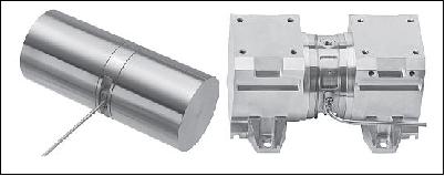
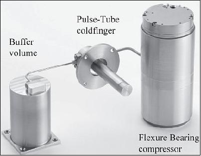
IIS operates within the MWIR (Mid-Wavelength Infrared) region of 3 - 5 µm at high spatial and thermal resolution. The sensing array is made of MCT (Mercury Cadmium Telluride) and hybridized with the ROIC (Read-Out-Integrated-Circuit) forming the FPA (Focal Plane Array). With a total heat load of 800 mW, the KOMPSAT-3A MWIR MCT detector is to be operated at 80 K. For those given conditions, the AIM SF400 compressor was chosen in conjunction with a ½" pulse-tube cold finger. Overall, the infrared imaging payload acquires imagery at a ground resolution of 5.5 m on a swath of 12 km. 21)
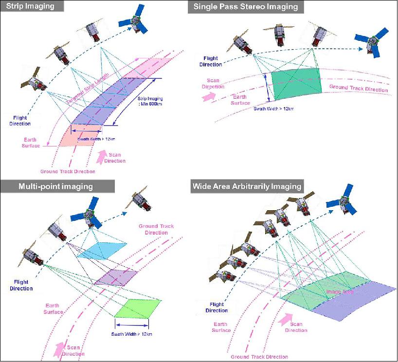
KOMPSAT-3A Imaging Modes
- Strip imaging is a scanning method in which the scan direction is aligned with satellite velocity. The satellite is fixed in LVLH coordinate and the yaw steering manoeuvre is automatically performed to eliminate the effect of the earth's rotation.
- Single-pass stereo imaging is a scanning method in which the scan direction is the same as strip imaging, but the satellite takes two images of the same target in the same pass. The first image is taken at a positive pitch tilt angle, and the second image is taken at a negative tilt angle. Therefore the two images of different viewpoints can be utilized to generate 3D images.
- Multi-point imaging is a scanning method in which the satellite takes an image and quickly rotates the body to the next position to take several images in a different location. While scanning, the satellite body is fixed in the LVLH coordinate.
- Wide arbitrary imaging is a scanning method in which the scan direction is different from the satellite velocity. Therefore, the ground track can be in an arbitrary direction such as a direct north direction, east direction, or west direction.
References
1) Daniel A. Pinkston, "Joining the Asia Space Race: South Korea's Space Program," Korea Economic Institute of America, 2014, URL: http://www.keia.org/sites/default/files/publications/kei_aps_2014_pinkston.pdf
2) "26 March 2015 KOMPSAT-3A Launch," ISC Kosmotras, March 26, 2015, URL: https://web.archive.org/web/20211026050628/http://www.kosmotras.ru/en/launch2015_eng/
3) Anatoly Zak, "Dnepr launches KompSat-3A," March 25, 2015, URL: http://www.russianspaceweb.com/dnepr-kompsat-3a-arirang-3a.html
4) Patrick Blau, "Silo-Launched Dnepr Rocket delivers KOMPSAT-3A to Orbit," Spaceflight 101, March 25, 2015, URL: http://www.spaceflight101.com/dnepr---kompsat-3a-launch-updates.html
5) Information provided by Sungdong Park, Chairman, Satrec Initiative Co., Ltd., Daejeon, Korea.
6) "UrtheCast and SIIS sign agreement for the global distribution of their respective portfolios," UrtheCast Press Release, 21 Dec. 2017, URL: http://investors.urthecast.com/file.aspx?IID=4388192&FID=391539306
7) "SIIS and UrtheCast sign agreement for the global distribution of their respective portfolios," SIIS, 21 Dec. 2017, URL: http://www.si-imaging.com/newsroom/?uid=235&mod=document
8) "SI Imaging Services," SIIS, 29 Sept. 2017, URL: http://www.si-imaging.com/aboutus/
9) Information provided by Moongyu Kim, President & CEO of SIIS (SI Imaging Services), Daejeon, Korea
10) "PhotoSat verifies the accuracy of survey data from the new KOMPSAT-3A satellite to 21cm in elevation," KOMPSAT -3A News Release, PhotoSat, SIIS, October 34, 2016, URL: http://www.photosat.ca/wp-content/uploads/2016/10/KOMPSAT-3A-survey-accuracy-PhotoSat-SIIS-jpegs-24oct2016-.pdf
11) "PhotoSat verifies accuracy of survey data from new KOMPSAT-3A satellite," Geospatial World, October 25, 2016, URL: https://www.geospatialworld.net/news-posts/photosat-
verifies-accuracy-survey-data-new-kompsat-3a-satellite/
12) Information provided by Moongyu Kim of SIIS, Daejeon, Korea.
13) "SI Imaging Services started KOMPSAT-3A commercial services," SIIS News, July 7, 2016, URL: http://www.si-imaging.com/ds6_1_1.html?db=new_bbs&n
o=104&c=view&page=1&SK=&SN=&kind3=&idx=
14) Information provided by Daewon Chung, head of the KARI Ground Systems Development Department, Daejeon, Korea.
15) Hwayeong Kim, Okchul Jung, Hyeonjeong Yim, Sang Il Ahn, "Analysis on the Minimization of Contact Overlap Time between KOMPSAT-3 and KOMPSAT-3A," Proceedings of the 25th International Symposium on Space Flight Dynamics, Munich, Germany, Oct. 19-23, 2015, URL: http://issfd.org/2015/files/downloads/papers/086_Kim.pdf
16) Moon-Jin Jeon, Sang-Rok Lee, Eunghyun Kim, Seong-Bin Lim, Seok-Weon Choi, "Launch and Early Operation Results of KOMPSAT-3A," Proceedings of the 14th International Conference on Space Operations (SpaceOps 2016), Daejeon, Korea, May 16-20, 2016, paper: AIAA 2016-2394, URL: http://arc.aiaa.org/doi/pdf/10.2514/6.2016-2394
17) http://www.yonhapnews.co.kr/bulletin/2015/0
4/14/0200000000AKR20150414089400017.HTML
18) SIIS (SI Imaging Services), April 14, 2015, URL: http://kompsat.satreci.com/ds6_1_1.html?db=new_bbs&n
o=44&c=view&page=1&SK=&SN=&kind3=&idx=
19) "Satrec Initiative Announces Agreement with Korea Aerospace Research Institute," SI, Nov. 15, 2012, URL: http://www.satreci.com/eng/ds1_1.html?tno=100&db=pr_board&no=22
20) https://web.archive.org/web/20160918150636/http://www.si-imaging.com/ds1_1_1.html
21) M. Mai, I. Rühlich, A. Schreiter, S. Zehner, "AIM-Space Cryocooler Programs," URL: https://smartech.gatech.edu/bitstream/handle/1853/38766/018.pdf
Spacecraft Launch Mission Status Sensor Complement References Back to top