KOMPSAT-6 (Korea Multi-Purpose Satellite-6) / Arirang-6
EO
Land
Multi-purpose imagery (land)
Land surface imagery
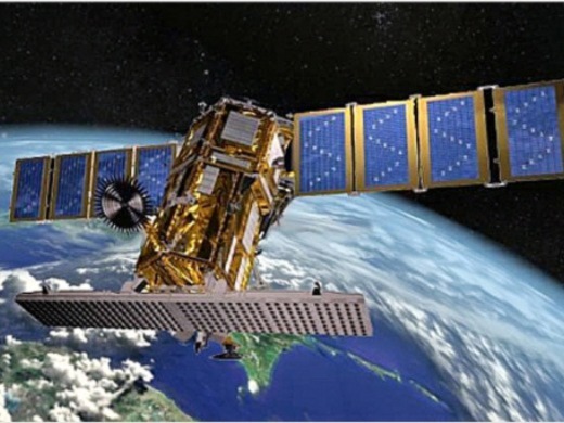
Planned for launch in December 2023, KOMPSAT-6 (Korea Multi-Purpose Satellite 6) is the second SAR (Synthetic Aperture Radar) imaging satellite developed by KARI (Korea Aerospace Research Institute), following on from KOMPSAT-5. KARI will also operate the satellite following launch. KOMPSAT-6 aims to provide high resolution radar imagery required in GIS (Geographical Information Systems), disaster & environment monitoring and ocean & land management.
Quick facts
Overview
| Mission type | EO |
| Agency | KARI |
| Mission status | Approved |
| Measurement domain | Land |
| Measurement category | Multi-purpose imagery (land), Landscape topography |
| Measurement detailed | Land surface imagery, Land surface topography |
| Instruments | SAR (KOMPSAT-6) |
| Instrument type | Imaging microwave radars |
| CEOS EO Handbook | See KOMPSAT-6 (Korea Multi-Purpose Satellite-6) / Arirang-6 summary |
Summary
Mission Capabilities
KOMPSAT-6 will carry two payloads, the XSAR instrument (X-Band Synthetic Aperture Radar) and the S-AIS (Satellite-Automatic Identification System). XSAR is a high resolution all-weather imager which has applications in mapping, GIS, environment and disaster monitoring as well as management of ocean and land. The S-AIS payload is a maritime wireless system used to identify position, heading, destination and cargo of larger vessels with the main purpose of collision prevention between larger vessels and with additional applications in maritime traffic management.
XSAR consists of the SSS (SAR Sensor Subsystem), DLS (Data Link Subsystem) and PLM (Payload Module). The SSS is comprised of the (SAR controller electronics), in charge of command and control of the SSS, the RFE (Radio Frequency Electronics), which carries out frequency up-converting and bandwidth multiplication for signal transmission, as well as down-converting and I/Q demodulating for signal reception, the FEI (Front End Interface), which provides RF (Radio Frequency) signal routing, the SAA (SAR Antenna Assembly), an active phased array, and the APS (Antenna Power Supply). The DLS manages data storage, handling and transmission, while the PLM consists of the structure, thermal control hardware and harness.
Performance Specifications
XSAR has 4 operational modes, High Resolution A, High Resolution B, Standard, and Wide Swath, with spatial resolutions 0.5 m, 1.0 m, 3.0 m and 20 m and swath widths 5 km, 10 km, 30 km and 100 km, respectively. The instrument’s operational frequency is 9.66 GHz (X-band), with a 320 mm wavelength and an incidence angle of 20°- 60°. It is capable of Single, Double or Quad multi-polarisation (HH, HV, VH, VV), with 1 Tbit onboard storage capacity. S-AIS operates in VHF (Very High Frequency) band, with 4 GB of data memory.
KOMPSAT-6 operates in a sun-synchronous dawn-dusk frozen orbit, with mean altitude of 550 km, inclination 98.1°, LTAN (Local Time on Ascending Node) 0600 hours and a 28 day repeat cycle.
Space and Hardware Components
The KOMPSAT-6 satellite bus was jointly constructed by LIG (Leading Innovation Group) Nex1 Co. Ltd., a Korean aerospace manufacturer owned by LIG Corp., and German company Airbus Defence and Space. The spacecraft has a design life of 4 years and a wet mass of 1,750 kg. The bus is capable of numerous operations in supporting system operations, including satellite timing, power and thermal management, attitude pointing and determination, orbit determination and orbit manoeuvring. These capabilities are enabled by a series of bus integrated subsystems, SMS (Structures and Mechanisms Subsystem), TCS (Thermal Control Subsystem), PS (Propulsion Subsystem), TC&R (Telemetry, Ranging and Command Subsystem), EPS (Electrical Power Subsystem) and FSW (Flight Software Subsystem). The spacecraft has an off-pointing angle of ±37°, and POD (Precise Orbit Determination) accuracy of 0.2 m, using a dual-frequency GPS receiver. In terms of RF communications, TT&C (Tracking, Telemetry and Control) data is transmitted in S-band, while payload data transmissions are in X-band, with a 600 Mbit/s data downlink rate.
KOMPSAT-6 (Korea Multi-Purpose Satellite-6) / Arirang-6
Spacecraft Launch Sensor Complement Ground Segment References
KOMPSAT-6 is the second SAR satellite of KARI (Korea Aerospace Research Institute) as a follow-on from KOMPSAT-5. The mission objective of KOMPSAT-6 system is the expedite provision of the spaceborne SAR (Synthetic Aperture Radar) images with high resolution required for the national demand in GIS (Geographical Information Systems), Ocean & Land management, Disaster monitoring, and Environment monitoring. The primary mission of KOMPSAT-6 system is to provide the SAR imagery of 0.5 m and 1 m resolution in the high resolution mode, 3 m resolution in standard mode, and 20 m resolution in the wide swath mode at an incidence angle of 45º. 1)
Spacecraft
The spacecraft will be built by LIG Nex1 Co. Ltd. of Korea and Airbus Defence and Space's of Friedrichshafen, Germany. The contract was signed in Seoul on February 24, 2014 by Hyokoo Lee, CEO of LIG Nex1 Co. Ltd and Eckard Settelmeyer, Head of Earth Observation of Space Systems in Germany. Seoul-based LIG Nex1 Co., a division of the LG Group and a major Korean defense contractor, will use the KOMPSAT-6 work to enter into a long-term cooperation with Airbus Defence and Space in the domain of spaceborne radar. LIG Nex1 is accountable to KARI (Korea Aerospace Research Institute) for handling all aspects of the radar sensor. KARI plans to launch the satellite in 2020 as a replacement and successor to KOMPSAT-5 (launch on Aug. 22, 2013). 2) 3) 4)

The spacecraft bus provides a number of functions to support the system operations. These functions consist of providing a stable platform for SAR payload, AIS payload, the state of health telemetry data, satellite timing, power and thermal management, attitude pointing and determination, and orbit determination. The spacecraft bus also provides the orbit maneuver capability necessary to maintain the orbit required for the KOMPSAT-6 mission.
The bus features the following subsystems: SMS (Structures and Mechanisms Subsystem), TCS (Thermal Control Subsystem ), AOCS (Attitude and Orbit Control Subsystem), PS (Propulsion Subsystem), TC&R (Telemetry, Command, and Ranging Subsystem), EPS (Electrical Power Subsystem), and FSW (Flight Software Subsystem). The key design features of KOMPSAT-6 spacecraft bus are described as follows:
- Integrated structure with hexagonal cross section
- Primary structure made out of CFRP (Carbon Fiber Reinforced Polymer)
- Fixed SAR antenna on a panel
- Fixed solar array with one deployable wing
- Panel-mounted units covered with MLI (Multi-Layered Insulation) tents
- 3-axis attitude control with zero momentum bias
- Dual-frequency GPS receiver for POD generation
- Passive & processor-controlled thermal control
- 1 N thrusters for precise orbit correction
- Solar array capability: 2.250 kW
The spacecraft bus uses the MIL-STD-1553B data bus interfaces for most of the spacecraft bus and payload to the IBMU (Integrated Bus Management Unit). The dual frequency GPS receiver provides the time, satellite position and velocity for on-orbit ephemeris, and L1/L2 frequency GPS pseudo-range and carrier phase data for post-processed precision orbit determination on ground. TC&RS includes S-band antennas, a RF assembly and redundant S-band transponders. AOCS provides 3-axis stabilization with off-pointing capability and yaw steering capability during imaging periods.
In addition, the spacecraft bus provides the mechanical and electrical interface to the launch vehicle, and the necessary strength and stiffness to deliver the satellite to mission orbit during launch, ascent, and insertion. For the case where the launch vehicle has placed the satellite into orbit within nominal dispersions from the desired mission orbit, the spacecraft bus provides the capability to correct the orbit through a series of orbit maneuvers to the final mission orbit.
Spacecraft design life | 5 years |
Spacecraft mass, power | 1,750 kg (wet mass), 2.250 kW |
Repeat Ground Track Maintenance | 250 m (3σ) |
POD (Precise Orbit Determination) accuracy | 20 cm (1σ), Dual-frequency GPS receiver |
Spacecraft off-pointing angle | ±37º |
RF communications | - S-band for TT&C data transmissions |
EPS (Electrical Power Subsystem)
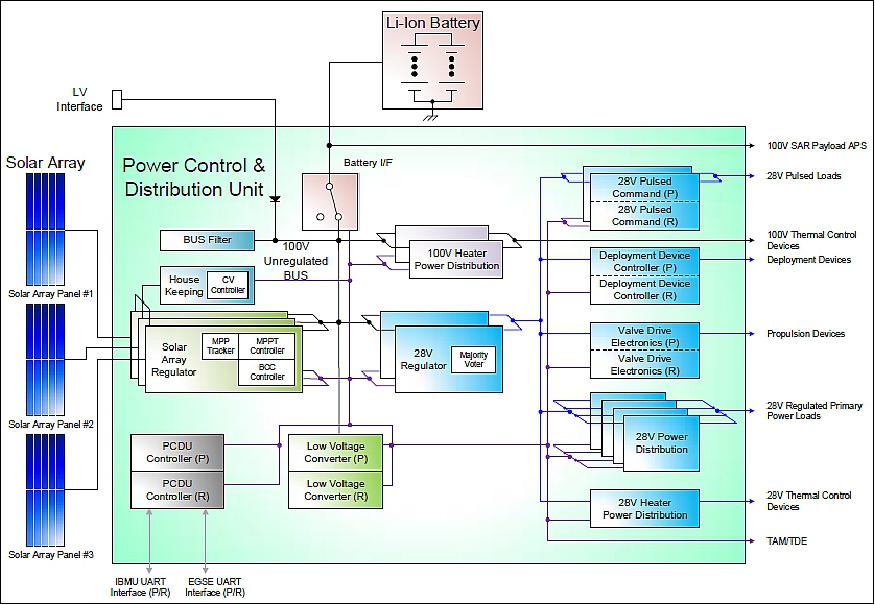
The EPS of KOMPSAT-6 uses TJ (Triple Junction) type solar panels for the generation of spacecraft power, the Li-Ion battery for the storage of spacecraft energy, and the PCDU (Power Control & Distribution Unit) for the power control and distribution. The capability of the solar panels was decided as 2,250 W at EOL (End of Lifetime) and the capacity of the battery was determined as 82 Ah at EOL to satisfy the systems mission and power requirements (Ref. 4).
The main functions of the PCDU are to provide the 100 V bus voltage, the heater power, the high level pulsed command, to distribute the power for the electronics units, and to protect the battery fault by the DNEL (Disconnect Non-Essential Load) and UV (Under Voltage) logic design. The electrical performance analysis was performed with the parameters based on the results of the electrical power systems design. The performance analysis results show that the designed electrical power systems are fully able to meet the satellite mission and the power requirements.
Design of the EPS: The KOMPSAT-6 applied the heritage electrical power systems design for low Earth orbit (LEO) satellite program and added new several electrical design concepts.
The EPS consist of the solar array, the battery, and the PCDU, which are shown in the electrical power systems block diagram of Figure 2 and described in more detail in subsequent sections.
Solar Array: The solar array converts solar energy to electrical energy and delivers it to the loads and the battery. The KOMPSAT-6's solar array consists of three panels, which are the bus fixed panel, the payload fixed panel, and the payload deployable panel. Each panel has 11 strings of 39 cells and cells are made up of the third generation triple-junction solar cells with minimum average cell efficiency of 28.7 % from SolAero Technologies of Albuquerque, NM, USA. The layout of the KOMPSAT-6 solar array panels is shown in Figure 3.

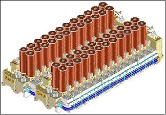
Battery: The battery accepts and stores the electrical energy from the solar array. The KOMPSAT-6's battery consists of 24 cells in series with 2 parallel Li-ion cells (2P24S), cell bypass circuits, and monitoring electronics (ISIS) from Saft (France). The configuration of the battery modules for the KOMPSAT-6 is shown in Figure 4.
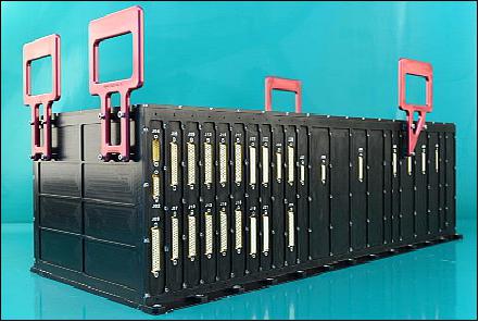
PCDU (Power Control & Distribution Unit): The PCDU generates and distributes 100 V of unregulated power and 28 V of regulated power to the bus and payload units via the controlled load switch. The PCDU also provides the secondary power for the PCDU internal module, the TDE (Torque Drive Electronics), and TAM (Three Axis Magnetometer). The heater power for thermal control hardware, high-level pulsed commands for load activation, and deployment activation signals for solar array panel are also provided by PCDU. PCDU applies the power limit operation mode to protect the buck-boost type solar array regulator and the DNEL & UV protection concept for battery protection. These concepts are described in more detail in sequent subsection.
KOMPSAT-6 EPS design: The new designs for the KOMPSAT-6 are the power limit mode for the solar array regulator protection, DNEL and UV concept for battery protection, the buckbooster converter scheme for solar array regulator, and 100 V bus voltage implementation for SAR payload high power consumption demand.
Operation Modes of Solar Array Regulator: The solar array regulator has three operational modes depending on the voltage of the unregulated primary power (100 V) bus and output power of the solar panels. The operation modes of the solar array regulator consist of the MPPT (Maximum Power Point Tracking) mode, the CV (Constant Voltage) mode, and the Power Limit mode similar with DET (Direct Energy Transfer) mode. The power limit mode is newly applied design to compensate the DET mode and this mode is to limit the power to protect the solar array regulator damage by the high power generation beyond the solar array regulator capability. The operation flow diagram for the solar array regulator operation modes is depicted in Figure 6.

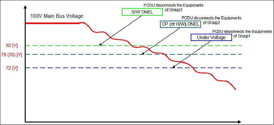
UV/DNEL Concept Design for Battery Protection: The UV and DNEL concept for battery protection are implemented in PCDU design. The KOMPSAT-6 will apply the UV and the DNEL scheme for power FDIR (Fault Detection and Isolation Recovery). The DNEL logic will disconnect equipment which is not essential for the operation in spacecraft safe mode when unregulated 100 V main bus voltage is less than DNEL voltage. The DNEL logic is not directly applied for 28 V regulated bus power. For the execution of DNEL, 100 V main bus voltage will be monitored by S/W or H/W logic. The S/W DNEL will react before the H/W DNEL takes an action for the DNEL event. The design concept scenario of the DNEL condition is illustrated in Figure 7.
The S/W DNEL logic will be performed. Next phase, if the main bus voltage drops to 78 V (or 76 V), the CP (Critical Parameter) DNEL (or H/W DNEL) will be executed. H/W DNEL is the backup of the CP DNEL when the CP DNEL is not activated correctly. In each case, PCDU will disconnect the equipment in the Group 3 for S/W DNEL and Group 2 for CP DNEL (or H/W DNEL), respectively. Finally, if the main bus voltage level decreases and arrives at the 72 V UV voltage level, the PCDU will disconnect all equipment except essential units (IBMU, S-band transponder) by the UV protection logic. The equipment groups for power system autonomy are shown in Table 2.
Classification | Units (Equipment) to be OFF |
Group 1 | Safe Hold Mode Heaters |
Group 2 | Units for System Stand-by |
Group 3 | SAR Payload Units |
Buck-Boost converter for solar array regulator: The PCDU adopted the buck-boost converter topology for the solar array regulator to accommodate 100 V bus voltage. The solar array regulator comparison for the heritage program and the KOMPSAT-6 is summarized in Table 3. The simplified circuit configuration of buck-boost power stage is shown in Figure 8.
Category | KOMPSAT-5 | KOMPSAT-6 |
Topology | Zero Ripple Buck | Buck-Boost |
Input | 55 - 110 V | 60 - 150 V |
Output | 31 - 51 V | 65 - 106.6 V |
Capability | 450 W per Converter | 450 W per Converter |
Redundancy | 2 of 3 Red. | 2 of 3 Red. |
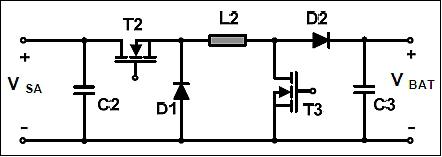
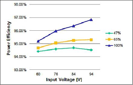
Figure 9 shows the measured efficiency of the solar array regulator according to the load condition. The efficiency of the solar array regulator is above 94 % required value at EOL.
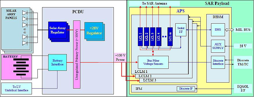
The 100 V Power Interface for SAR Payload: The bus voltage was selected as 100 V to lower the current level, because the SAR payload requires the high power during the radar operation. The power interface between the PCDU and the APS (Antenna Power Supply) was optimized to minimize the power loss as shown in Figure 10. The APS unit to supply 100 V power for the SAR antenna consists of three LCLM (Latching Current Limiter Module), an IFM (Interface Module), and a DHSM (Data Handling System Module).
Performance Analysis Results of Electrical Power Systems
In order to demonstrate the design maturity of the electrical power systems and estimate the dimensioning of the solar array & battery to support the KOMPSAT-6 mission, the performance analysis has been performed with the parameters based on the designed results.
Requirements for Electrical Power Systems: The KOMPSAT-6 has the following requirements which are related with the mission, the power, and the energy balance for the electrical power systems.
Mission requirements: The mission requirements for the electrical power systems are shown as follows:
• The spacecraft bus shall provide the required power for the continuously 150 second imaging operation of SSS (SAR Sensor Subsystem) per Korean peninsula pass where an eclipse occurs in orbit time frame.
• The spacecraft bus shall provide the required power for the continuously 150 second imaging operation of SSS per every orbit where no eclipse occurs in orbit time frame.
Power requirements: The power requirements for the electrical power systems are shown as follows:
• The spacecraft bus shall generate orbit average power without eclipse occurrence shall not be less than or equal to 2,250 W at the end of its mission lifetime.
• The maximum capacity of battery at EOL shall provide at least 82 Ah with an assumption of 8% degradation over the mission lifetime.
• The average battery depth of discharge (DOD) shall not exceed average 20 % for one day in case of one cell package failure.
• The maximum battery depth of discharge (DOD) shall not exceed 35 % for one day in case of one cell package failure.
Energy balance requirement: The energy balance requirement for the electrical power systems is shown as follows:
• The spacecraft bus shall be capable of providing 1 day energy balance (to satisfy the full battery recharge) with the maximum imaging time for both eclipse and non-eclipse occurrence.
Parameters and assumptions for electrical performance analysis: The parameters for electrical performance analysis are described in this section.
Parameters summary: The parameters for electrical performance analysis are summarized in Table 4. Some parameters are defined from the supplier's data and others are assumed from the design heritage.
Solar array regulator efficiency | 94% |
28 V regulator efficiency | 93% |
Secondary converter efficiency | 70% |
Harness losses | 1% |
Required power at EOL | 2,250 W |
Predicted Pmp at EOL (72 degrees C) | 2,258 W |
Predicted Pmp at BOL (28 degrees C) | 2,874 W |
Launch
Launch: A launch of the KOMPSAT-6 satellite of KARI is planned for 2020 with the Angara 1.2 vehicle of ILS (International Launch Services) from the Plesetsk Cosmodrome in Russia. 5)
Orbit: Sun-synchronous ground repeat track dawn-dusk frozen orbit, mean altitude = 505 km, inclination = 97.42º, LTAN (Local Time on Ascending Node) = 6 hours, the repeat cycle is 11 days.
Sensor Complement
XSAR (X-band Synthetic Aperture Radar)
XSAR is a multi-mode operations instrument consisting of the SSS (SAR Sensor Subsystem), the DLS (Data Link Subsystem) and the PLM (Payload Module). The SSS is equipped with an active phased array antenna, with electronic scanning capabilities in the azimuth and the elevation planes. The DLS is in charge of the storage and ground transmission of the SAR sensor data and of the ancillary data.
The following key characteristics are considered for XSAR payload architecture design: 6)
• X-band Active Phased Array Synthetic Aperture Radar with dual H/V polarized wideband slotted waveguide antenna and T/R modules
• Electronic beam steering capability in both azimuth and elevation plane
• Multi-mode operation over a wide access region by SAR techniques; High resolution mode by sliding spotlight, Standard mode by stripmap technique and Wideswath mode by TOPS (Terrain Observation with Progressive Scan) technique
• ATI/GMTI (Along-Track Interferometry/Ground Moving Target Indication) mode for experimental applications 7)
• High speed data rate downlink with two channels
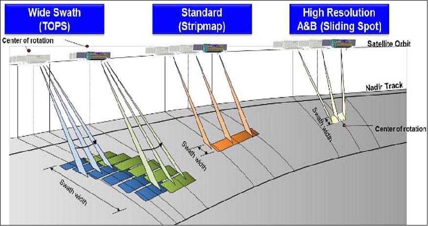
The SSS comprises the following equipments:
• SCE (SAR Controller Electronics), which includes DTCU and DRU. The SCE is in charge of the command and control of the SSS to achieve the SAR mission. It provides wideband chirp signal generation, digitization, smart digital filtering and block adaptive quantization for data reduction. It also manages radar timing control and redundancy configuration of SSS.
• RFE (Radio Frequency Electronics). RFE performs frequency up-converting and bandwidth multiplication for transmitting signal, frequency down-converting and I/Q demodulating for receiving signal, and reference clock provision.
• FEI (Front End Interface). The FEI provides RF signal routing for nominal operation and calibration, and manages amplification and distribution RF signal.
• SAA (SAR Antenna Assembly). The SAA is an active phased array and it is able to operate different beam characteristics for transmission and reception. It manages electrical beam steering for horizontal and vertical direction. It consists of two leaves with 12 IFETs as basic elements and the fixed antenna structure.
• APS (Antenna Power Supply). The APS provides 100 V power to SAA and FEI which is received from the Platform PCDU (Power Control and Distribution Unit).
The SSS requires the internal calibration resources by hardware network and software tools in order to achieve radiometric performance.
The DLS (Data Link Subsystem) manages data storage, data handling and data transmission to ground station. DLS comprises the following equipments:
- DSHA (Data Storage & Handling Assembly). DSHA controls the SAR data acquisition and storage, data formatting and coding according to CCSDS standard, and data encryption.
- XTA (X-band Transmission Assembly). XTA provides baseband data modulation onto two carriers and power amplification of each downlink channel.
- XAA (X-band Antenna Assembly). XAA consists of two fixed wide coverage antenna for transmission to ground station of modulated data stream with an isoflux shaped radiation pattern.
PLM (Payload Module) consists of the structure, thermal control hardware and harness. The PLM structure is configured as one frame concept in the spacecraft structure without discrimination of platform and payload. This concept is able to use the fixed SAR antenna on structure without a deployment mechanism. The satellite structure is designed using CFRP panels to reduce the satellite mass and enhance the thermal characteristics. The payload thermal hardware is designed to maintain the payload component within the specified temperature limits during all mission lifetime using passive thermal control method such as SSM foil, heaters and sensors.
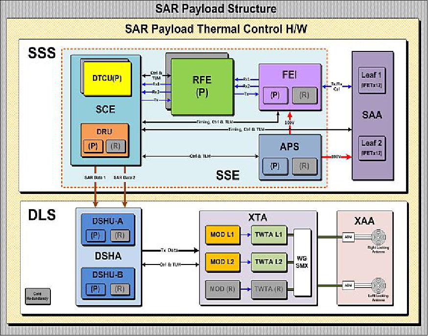
The SSS provides the following functions:
• Transmit equipment for signal generation and distributed transmit signal high power amplification
• Receive equipment for distributed receive signal low noise amplification, coherent down-conversion and digitization
• The SAA (SAR Antenna Assembly) with real-time [PRI to PRI (Pulse Repetition Interval)] beam forming capability in azimuth and elevation via phase and amplitude control including temperature compensation and providing single phase as well as dual phase center
• Quad linear polarization(HH, VV, VH, HV) with dual coherent HH/HV and VV/VH
• Quad linear polarization(HH, VV, VH, HV) with dual coherent HH/HV and VV/VH
• Command and control functionality for agile and flexible operation.
The DLS comprises all the functions necessary for acquisition, storage and handling of data generated by the SSS, and for real-time or near real-time transmission to the ground station.
Design life | 5 years |
Operational frequency | 9.66 GHz (X-band) or 3.2 cm wavelength |
Operational modes | - High Resolution-A: 0.5 m resolution, 5 km swath width |
Image acquisition time | 150 seconds per orbit |
Multi-polarization | - Single: HH, HV, VV, VH |
Incidence angle | 20-60º |
NESZ (Noise-Equivalent Sigma Zero) | -20 dB |
Onboard data storage capability | 1 Tbit |
Downlink data rate | 600 Mbit/s |
SAR payload development
The KOMPSAT-6 payload system design and development is performed by the leading of KARI payload team. Korea industries are involved in the development of the SSS (SAR Sensor Subsystem), DLS (Data Link Subsystem) and PLM (Payload Module). The overseas partners are engaged in the payload unit development, in a mutual cooperative fashion.
The core development equipment of the SAR payload are the SCE (SAR Controller Electronics) and the DSHA (Data Storage& Handling Assembly). The core units are being developed by the KARI payload team and Korea industries based on SAR technology and the KOMPSAT program heritage. The PGSE (Payload Ground Support Equipment) are also being developed in accordance with payload verification and payload test plan, respectively. The payload AIT (Assembly, Integration and Test) activities will be performed at KARI facilities. For the next step, the detailed payload system design and units development will be executed according to its specification. In particular, the engineering model of the SCE (SAR Controller Electronics) and DSHA (Data Storage& Handling Assembly) are under development.
S-AIS (Satellite-Automatic Identification System) payload
AIS is a maritime wireless system designed to identify basic parameters relating to the position, heading, destination and cargo of larger vessels with the main purpose of collision avoidance. The AIS payload is the secondary payload of the KOMPSAT-6 satellite. The AIS payload receives and provides the AIS signal data for ship collision avoidance and traffic management. The AIS objectives are: 8)
• AIS signal collection from vessels on sea
• Raw data sampling for OGP (On Ground Processing) mode
• Demodulation of AIS burst signals for OBP (On Board Processing) mode.
The AIS payload for KOMPSAT-6 consist of the AIS receivers and the AIS antennas. The satellite AIS receivers are able to disentangle these multiple collision signals of the ground target region and reconstruct the original messages. The AIS receivers are able to operate in both frequency spectrum capture modes (Raw/OGP) and on-board processing (OBP) mode allowing simultaneous operation.
VHF band antennas are needed for the AIS signal reception. Multiple VHF antennas can be used for better AIS signal reception. An antenna deployment mechanism is applied for deploying the antennas after the satellite deployment into orbit.
Design life | 5 years |
Mass, power | 5 kg, 7 W |
Operational modes | OBP (On-board Processing), OGP (On-ground Processing) |
Operational frequency | VHF band |
Data memory | 4 GB |
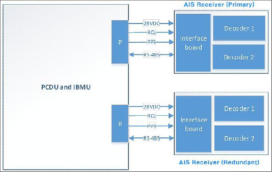
Electrical Interface Design: The IBMU (Integrated Bus Management Unit) primary (RCL, PPS and COM) is connected to the AIS receiver primary (hot), and the IBMU redundant is connected to the AIS receiver redundant (cold), as shown in Figure 13. The AIS payload has the following electrical interface characteristics.
- RS-422/RS-485: 115.2 kb/s, 230.4 kb/s, 460.8 kbaud/s and 921.6 kbaud/s (baud rate is selectable)
- PPS input: RS-422/RS-485
- Redundancy control: RS-422/RS-485
- Connectors: Antennas: SMA 50 Ohm female
- Power: High performance micro D-subminiature
- Serial: High performance micro D-subminiature
This configuration offers complete redundancy on all parts and quadruple redundancy on the decoder boards and the interface boards. The Interface Board contains an RF front-end filter, one LNA (Low Noise Amplifier) for each antenna, external interface connectors, board connectors, power supply, and communication transceivers.
Mechanical Interface Design: The mechanical interfaces design has been carried out for the AIS receiver and the AIS antennas mounting on the spacecraft. The unit accommodation design for KOMPSAT-6 is in a preliminary design phase so far. Mounting configurations of AIS receiver and locations of the antennas on the spacecraft are shown in Figure 14 for the AIS receiver and Figure 15 for the AIS antennas, respectively. 9)
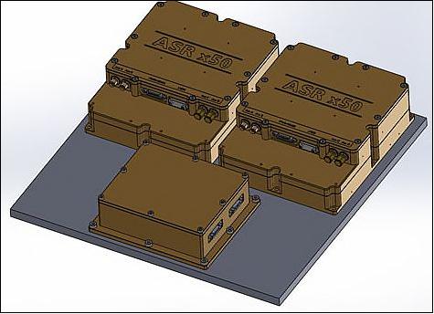

The AIS receiver consists of three interconnected boards in a housing with all external connectors mounted at a recessed top front. The mounting points to the satellite structure are placed on a single plane at the bottom of the receiver. The enclosure is made as a non-magnetic metallic case which forms an all-enclosing electromagnetic and radiation shield. The mechanical design assumes a spacecraft manufacturing tolerance of ±0.1 mm.
ETRI (Electronics and Telecommunications Research Institute) of Daejeon is to design and develop the S-AIS system for KOMPSAT-6.
Ground Segment
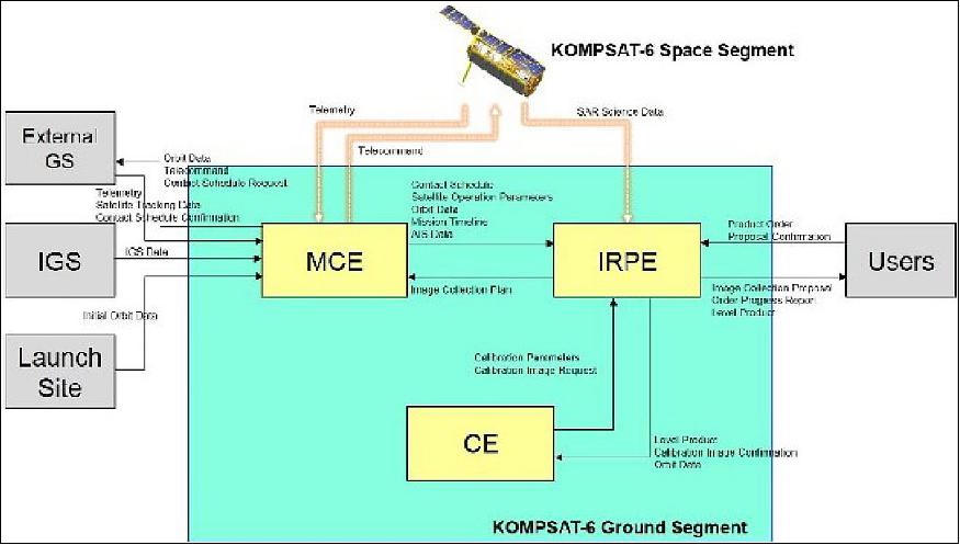
The ground segment of the KOMPSAT-6 system is under design to comply with the requirements assigned to the ground segment. According to the requirement analysis, the ground segment is designed to be comprised of three elements, which consist of the MCE (Mission Control Element) , IRPE (Image Reception and Processing Element) and the CE (Calibration Element), respectively. Both internal and external interfaces of the ground segment are under design considering all operational aspects. As a result, the ground segment is expected to have functionalities such as monitoring the state of health of the satellite, programming and control for the operation, receiving and processing SAR observation data to provide standard products to the user community. 10)
The KOMPSAT-6 ground segment is to be operated based on mission operation procedures in support for mission scheduling and planning activities and observation data reception and processing activities. Detailed procedures for mission scheduling and planning activities consist of the following support functions:
1) Reception of product orders from users
2) Generation of image collection proposal based on the order analysis result
3) Generation of image collection plan
4) Generation of mission plan including satellite operation timelines
5) Command generation and transmission to the satellite.
The KGS is located at the KARI (Korea Aerospace Research Institute) site; it is comprised of the MCE (Mission Control Element), IRPE (Image Reception and Processing Element) and CE (Calibration Element). The satellite interfaces with ground station via both S-band and X-band communications capabilities. The launch segment is comprised of the launch vehicle, launch related equipment, and launch services/operations required for delivery the satellite into mission orbit.
The KOMPSAT-6 external interfaces include the King Sejong station on Antarctica to support urgent imaging request with looking mode change and contingency support, additional ground stations in support of LEOP (Launch and Early Orbit Phase), and the IGS (International GPS Service) data center providing high accuracy ground based GPS data products to KARI for POD (Precision Orbit Determination) processing.
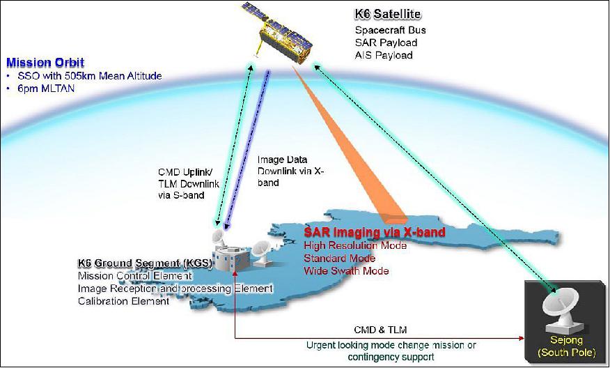
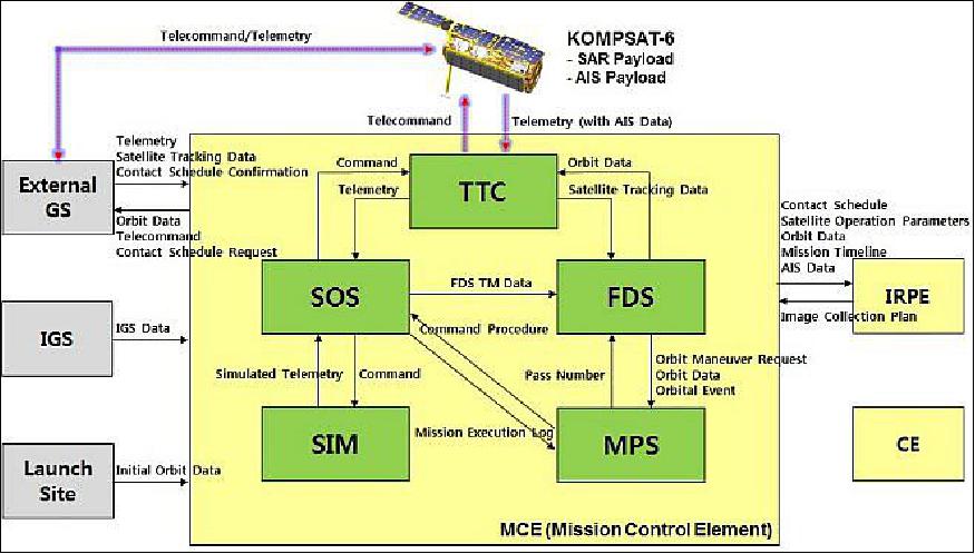
MCE (Mission Control Element): The MCE provides the satellite control capabilities that allow operators to carry out the KOMPSAT-6 mission with mission planning, command generation and transmission, telemetry processing and SOH (State of Health) monitoring, space flight dynamics support, and simulation for satellite operation. The MCE is designed to provide the S-band RF communication capability which links it with the KOMPSAT-6 satellite in space for the command uplink, ranging and telemetry downlink including AIS (Automatic Identification System) data. These key functions of the MCE are summarized as follows:
• Communication with KOMPSAT-6 satellite via S-band RF link
• Satellite Control and Monitoring
• Mission Activity Planning and Command Procedure Planning
• Orbit Determination, Prediction, and Maintenance
• Satellite simulation
The MCE is designed to consist of five subsystems. The TTC (Telemetry, Tracking & Command ) subsystem provides the functionality for telecommand and telemetry communications with the KOMPSAT-6 satellite via S-band RF link. The SOS (Satellite Operation Subsystem) provides the functionality for command generation and transmission to the satellite, monitoring SOH of the satellite and data processing for the AIS as well as the housekeeping telemetry. The MPS (Mission Panning Subsystem) provides overall satellite mission planning, incorporates requests, defines KOMPSAT-6 configurations, and prepares the operation timeline. The FDS (Flight Dynamics Subsystem) provides space flight dynamics support such as orbit determination, orbit prediction, and orbit maneuvers. The SIM (Simulator) provides the function of command/telemetry simulation, operator training and satellite visualization. Figure 18 depicts the architecture and interfaces of the MCE.
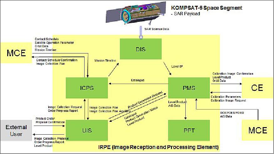
IRPE (Image Reception and Processing Element): The IRPE is designed to provide the capability of receiving RF signal from KOMPSAT-6 satellite via X-band, retrieving SAR observation data, generating Level 0 products, standard products and value-added products if needed, and providing level products to users. The IRPE consists of five subsystems, which are UIS (User Interface Subsystem), ICPS (Image Collection Planning Subsystem), DIS (Direct Ingestion Subsystem ), PMS (Product Management Subsystem ), and PPT (Post Processing Tool). Figure 19 shows the architecture and interfaces of the IRPE.
The UIS provides functionalities for the reception, management of product order, generating image collection proposal based on feasibility study and image collection request as the confirmation on image collection proposal and submitting product generation request for the generation of standard products. The ICPS is designed to have functionalities such as the generation of image collection plan which are essential in detailed command parameters for the SAR payload operation, management of image collection planning status. To make the image collection plan optimal in view of resources, the ICPS provides the capability of managing resources related to the SAR payload operation. The DIS, in connection with the X-band antenna system, provides functionalities such as scheduling X-band RF signal reception, X-band RF signal receiving and status monitoring, analog to digital conversion to extract CADU (Channel Access Data Unit) frames for retrieving SAR source packet data. The PMS is designed to have functionalities such as catalog data generation, product generation status control and monitoring and standard product generation. Finally the PPT is designed to be used for SAR application such as interferometry, ATI/GMTI (Along-Track Interferometry/Ground Moving Target Indicator), the fusion of SAR data with AIS data, and so on.
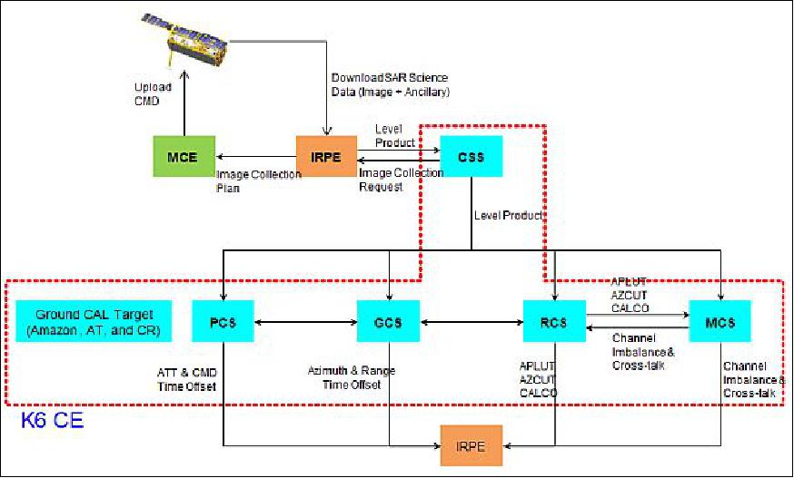
CE (Calibration Element): The SAR calibration encompasses the activities or processes to link the values of acquired SAR images to reflectivity of ground targets (back scattering coefficient) by achieving the highest instrument observation accuracy of measurements. The CE, as part of the KOMPSAT-6 ground segment, provides the capabilities or tools to achieve efficient SAR calibration by providing the following functions: 1) range & azimuth antenna pointing offset measurement, 2) geometric range & azimuth offset measurement using point target, 3) product coverage location error measurement, 4) antenna pattern verification, 5) absolute radiometric calibration factor evaluation, 6) polarimetric effects (channel imbalance & cross-talk) compensation, 7) long-term & daily calibration image scheduling.
To fulfil these functions, the CE is designed to consist of five subsystems. The PCS (Pointing Calibration Subsystem) is used in calibrating the range and azimuth antenna pointing offsets by using notch beam pattern. The GCS (Geometric Calibration Subsystem) is to be used in calibrating pixel localization offsets by using point target and measures image product coverage location errors. The RCS (Radiometric Calibration Subsystem) is prepared for verifying reference antenna pattern with the measured antenna pattern from images and ground receiver, and also used in calculating absolute radiometric calibration factors. The MCS (Multi-polarimetric Calibration Subsystem) provides a means to compensate polarimetric distortions such as channel imbalance and cross-talk. Finally, the CSS (Calibration Scheduling Subsystem) is used for organizing the long-term and daily calibration image collection schedule. Figure 20 shows the architecture of CE with internal and external interfaces.
References
1) Seon-Ho Lee, Jae-Cheol Yoon, Jin-Hee Kim, "KOMPSAT-6 Mission, Operation Concept, and System Design," Proceedings of EUSAR 2016, 11th European Conference on Synthetic Aperture Radar, Hamburg, Germany, June 6-9, 2016
2) "Airbus Defence and Space sign contract to deliver space radar to the Republic of Korea,", Airbus DS Press Release, March 14, 2014, URL: https://airbusdefenceandspace.com/newsroom/news-and-features/airbus-defence-
and-space-sign-contract-to-deliver-space-radar-to-the-republic-of-korea/
3) Peter B. de Selding, "German-Korean Industrial Team To Build KOMPSAT-6 Radar Imager," Space News, Feb. 26, 2014, URL: http://www.spacenews.com/article/financial-report/39625german
-korean-industrial-team-to-build-kompsat-6-radar-imager
4) Young-Jin Won, "The Electrical Power Systems Design and the Performance Analysis for the Second Korean SAR Satellite," Proceedings of the 70th IAC (International Astronautical Congress), Washington DC, USA, 21-25 October 2019, paper: IAC-19-C3.3.3 , URL: https://iafastro.directory/iac/proceedings/IAC-19/
IAC-19/C3/3/manuscripts/IAC-19,C3,3,3,x49909.pdf
5) "ILS's First Contract With Korea Aerospace Research Institute To Launch Angara 1.2 & KOMPSAT-6," Satnews Daily, Aug. 2, 2016, URL: http://www.satnews.com/story.php?number=976279666
6) Yong Chul Hwang, Chang Ho Nam, Ui Young Pak, Se Young Kim, Jeong Ho Lee, "KOMPSAT-6 SAR Payload System Design," Proceedings of EUSAR 2016, 11th European Conference on Synthetic Aperture Radar, Hamburg, Germany, June 6-9, 2016
7) Dochul Yang, Okchul Jung, Donghan, Lee, "KOMPSAT-5/6 SAR Interferometry," Proceedings of EUSAR 2016, 11th European Conference on Synthetic Aperture Radar, Hamburg, Germany, June 6-9, 2016
8) Yong-Min Lee, Jin-Ho Jo, Byoung-Sun Lee, "Preliminary Design of S-AIS Payload for KOMPSAT-6," SPACOMM 2016 : The Eighth International Conference on Advances in Satellite and Space Communications, Lisbon, Portugal, Feb. 21-25, 2016, URL: https://www.thinkmind.org/download.php?articleid=spacomm_2016_2_20_20016
9) Design Definition File Summary Report, Issue 1A, ASRx50-KSX-DDF-014, Kongsberg Seatex AS, 2015
10) Chiho Kang, Okchul Jung, Taebong Oh, Dochul Yang, Gabho Jeun, "Operation concept of KOMPSAT-6 ground segment," Proceedings of EUSAR 2016, 11th European Conference on Synthetic Aperture Radar, Hamburg, Germany, June 6-9, 2016
The information compiled and edited in this article was provided by Herbert J. Kramer from his documentation of: "Observation of the Earth and Its Environment: Survey of Missions and Sensors" (Springer Verlag) as well as many other sources after the publication of the 4th edition in 2002. - Comments and corrections to this article are always welcome for further updates (eoportal@symbios.space).
Spacecraft Launch Sensor Complement Ground Segment References Back to top