LAICE (Lower Atmosphere/Ionosphere Coupling Experiment)
EO
Atmosphere
Planned
University of Illinois
Quick facts
Overview
| Mission type | EO |
| Agency | University of Illinois |
| Mission status | Planned |
| Measurement domain | Atmosphere |
| CEOS EO Handbook | See LAICE (Lower Atmosphere/Ionosphere Coupling Experiment) summary |
LAICE (Lower Atmosphere/Ionosphere Coupling Experiment)
Overview Spacecraft Launch Sensor Complement References
Overview
LAICE is is a collaborative project between the University of Illinois(UI) at Urbana-Champaign, IL, and the Virginia Polytechnic Institute and State University, Blacksburg, VA (aka Virginia Tech), which seeks to perform atmospheric gravity wave studies via in-situ measurements of wave perturbations in the ionosphere and remote sensing of the middle atmosphere. These measurements can then be correlated with weather maps of the lower atmosphere, allowing for atmospheric coupling studies over a wide altitude range. 1) 2)
LAICE is a US NFS (National Science Foundation) funded aeronomy CubeSat, and the first publicly funded, University-constructed satellite to use the "6U" form factor in the United States. The project formally began in 2013, and is expected to launch in early 2016.
LAICE is based on the University of Illinois designed 'Illinisat-2' generic picosatellite bus system. Illinisat-2 is a scalable CubeSat platform that handles all communication, power, command and data handling, and attitude determination and control needs for the satellite, using only 0.75U of volume. This frees all remaining extended volume for use by potential payloads. While Illinisat-2 buses have been developed primarily for 1.5 to 3U form factors, the expansion to a 6U, double-wide form was a logical, and moderately straightforward extension of the design.
Responsibility for construction of LAICE is divided into three primary working groups. The University of Illinois Advanced Research for the Exploration of Space Center, the developers of Illinisat-2 are responsible for all bus related development and testing. The University of Illinois' Remote Sensing and Space Sciences group in the Electrical and Computer Engineering Department is responsible for the remote sensing payloads. Finally, Virginia Tech is responsible for the development and testing of the in-situ sensing payloads, as well as being the lead center on the overall mission.
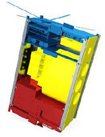
While the payloads only benefit from the expansion to a 6U form, granting them significant extra mass and volume, this design does come with some new design challenges. It required a complete rebuild of the satellite's power system, to accommodate the superior power generation, as well as an update to the satellite structure. Unlike the standardized 1U to 3U form factors, the 6U form is not yet common, and different potential launch vehicle deployers offer unique takes on its dimensions and interface.
The LAICE mission has two primary science objectives.
• First, it seeks to observe gravity waves with large vertical wavelengths via in-situ measurements of ion and neutral density fluctuations at lower F-region heights and correlate these with remote sensing measurements of wave-induced airglow perturbations in the upper mesosphere.
• Second, it will produce global maps of active gravity wave regions in the mid- and low-latitude ionosphere over multiple seasons at all local times, with the goal to quantitatively compare and correlate these waves with terrestrial weather systems via ray-trace modelling.
To accomplish these two goals, four science payloads are flying on board LAICE. To observe night time airglows, the University of Illinois-supplied photometer payload aims in the nadir direction, and has four photometer channels observing different wavelengths associated with 2 airglow emissions. The remaining three payloads are focused at the in-situ sensing objectives. The ion density and temperature is determined using a retarding potential analyzer (RPA). Finally, the LINAS (LAICE Ionization gauge Neutral Atmosphere Sensor) and the SNeuPI (Space Neutral Pressure Instrument) share an aperture and handle the neutral density detection. The development of the latter three instruments is under the guidance of Virginia Tech.
Background: Gravity waves are produced at low altitudes by convective weather systems, auroral heating during magnetic storms, and other natural perturbations. They carry energy upwards into the ionosphere, where they can provide the seed energy to create plasma density perturbations in the lower ionosphere. These ionospheric disturbances can disrupt and/or distort radio propagation by causing phase & amplitude scintillation, as well as multipath distortion over a wide range of frequencies from HF to the microwave region. These gravity-wave effects should be observable in LEO at low & mid-latitudes.
Spacecraft
Unlike the 1U to 3U configurations which are carefully regulated by the CubeSat Design Specification, there is not a single design specification for the 6U form factor. Each deployment system supplies its own payload design recommendations, and among the available deployers, there has been no standardization. The two deployers that are furthest along are the CSD (Canisterized Satellite Dispenser) of PSC (Planetary Systems Corporation) , and the NASA Ames NLAS (Nanosatellite Launch Adapter System). As the launch provider has not finalized the deployment system to be used, the 6U IlliniSat-2 bus and LAICE has been designed for a last-minute part swap to support either deployer. It is anticipated, that a decision will happen before environmental testing occurs, and that only the appropriate hardware need to be tested.
Bus structure: The IlliniSat-2 bus frame consists of a rail and plate design (Figure 2, left) whereby the satellite comprises of three plates (service, middle, and payload) and a set of connecting rails. The plates support the satellite electronics, antenna, batteries, and payloads, while the rails support the solar panels and connect the plates. The two plates attach to the rails via 12 screws points each. These parts are machined from 6061-T6 aluminum and then anodized or iridited, depending on the component.
The expansion to 6U form factor necessitated additional support structure for the IlliniSat-2 system – two flat rails were added, and the overall height of the satellite increased from 340.5 mm to 356 mm. Further, LAICE-specific modifications were made to the structure in order to accommodate the in-situ sensor's volume and support requirements, leading to a shortening of the rails despite the overall increase in the satellite, and transferring part of their load path to a larger, custom payload plate.
Another important update to the Illinisat-2 bus derives from the deployer accommodation requirements. The NASA Ames NLAS has a CubeSat-like corner-rail system with a pre-loaded push-plate, much like the original P-POD, and aside from the geometric increase in size, no additional changes were necessary. The CSD of PSC, on the other hand, utilizes a clamping system to a set of rail tabs on one of the surfaces of the satellite, and does not have a pre-loaded push-plate. By designing a variant of the rails with this tab running their entire length, the Illinisat-2 bus is compatible with the PSC deployer as well. The CSD system also requires a different aluminum alloy to be used when compared to the NASA system or the original CubeSat Design Specification.
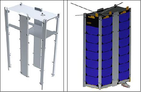
The service plate supports the primary satellite subsystems. This includes the subsystem stack (power board, C&DH board, Z-axis magnetic torque, and optional payload interface board) as well as the CadetU radios and radio interface board. Externally, the service plate houses feet separation springs, separation switched, and the satellites communications antenna.
The middle plate carries the battery packs. Its large thermal mass helps diffuse heat from the batteries to the rails where it is thereby conduct to the service plate and solar panels to be radiated out. There are two cutouts in this plate – the smaller one to pass cable harness from the payloads to the subsystem stack and the larger one to accommodate the PMT payload for the LAICE mission.
Both plates attach to the rails via 12 screw points each. The bus has a total of six rails that can be seen in Figure 2 right: two flat rails and four corner rails. All of them have small tabs to support the integration with solar panels.
ADCS (Attitude Determination and Control Subsystem): The ADCS is comprised of a series of 3-axis magnetometers and torque coils, as well as accelerometers and photodiodes, all of which are mounted to solar panels (with the exception of the Z-axis torquers). The satellite uses the 3-axis magnetometers to determine the strength and direction of the earth's magnetic field. The magnetic field data is combined with the knowledge of the satellite's orbit (which is propagated internally) to determine the satellite's attitude, and calculating the change in magnetic fields allows the satellite to determine its angular velocity. The magnetometers and torquers each run their own local microcontroller, while the flex cable itself has a microcontroller for use with the low level sensors (such as the accelerometers and photodiodes). All flex-cable mounted devices communicate back to the central processor on an RS-485 bus line. Each magnetometer consists of the HMC1053 magnetometer chip and a 3-channel 16-bit ADC, and is controlled by the PIC microcontroller.
Each solar panel has a small photoresistor mounted to its outer face. By using several sensors, it is possible to determine the pose of the spacecraft with respect to the sun. This is necessary for a Triad determination algorithm, and can improve convergence of the EKF (Extended Kalman Filter) determination algorithm.
A three-axis accelerometer will be mounted to the inside face of each solar panel on the solar panel flexible power/instrumentation harness. The accelerometer is only used to assist in reconciling discrepancies in the determination and control system.
The attitude sensors on board are the gyros, magnetometers and sun sensors (or photodiodes), while the only actuators are magnetorquers.
C&DH subsystem: The C&DH subsystem features two boards – the daughter and the carrier. The daughter card has the Cortex A8 processor (and a NAND flash memory, plus few other chips). This daughter card is mounted on a base carrier board using a JAE MM80-204B1-1 SODIMM connector – this base board contains all the peripheral ports.
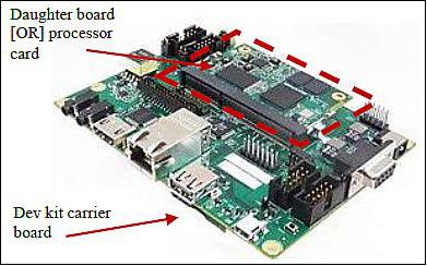
The C&DH board will connect to the power board through a backbone connector, containing pins to two UART ports – one to the housekeeping sensors (on the solar panel via the flex cable) and the other to the power board diagnostics that provides information about the batteries. The other UART ports connecting the C&DH board to the two payloads and the radio come in through harnesses. This backbone connector also supplies a 3.3 V power line and ground line to the C&DH board. Flash memory of 1 GB is provided on the daughter card to store mission critical operating system data and flight software. The 2 GB on the carrier board is split into two 1GB arrays of memory, with simultaneous write issued commands to both at any time. Using these, the C&DH system is set up so that all science data is stored once redundant, and the mission critical operating system data is stored twice redundant.
EPS (Electrical Power Subsystem): For the LAICE mission, only five of six possible solar panels are present due to the nadir-looking requirements of one of the payloads. The power board will use three 2 A maximum power point tracking battery chargers, one for each face of the satellite that has solar panels. A resistor divider network limits the maximum voltage that the chargers can set for the battery stack, which will be set somewhere within the 8.4V-8.7 V range. The battery assembly contains the battery cells and other electronics needed to protect it – the cell balancers, overvoltage protection, cut-off switches and temperature control circuitry. The Li-ion battery can store 38 Whr of energy.
RF communications: The communication system uses the CadetU radio manufactured by L3Communications and a single antenna. It operates in an allocated atmospheric band, yet to be allocated, but likely in the 460-470 MHz range (UHF), with a maximum transmit power of 4 W. It will download the science data at 2 Mbit/s to a designated ground station (18 m UHF antenna) at NASA Wallops, which has also a 20 m dish antenna. These transmission opportunities occur about four times/day.

The LAICE nanosatellite (6U CubeSat) has a mass of 12 kg and a size of 20 cm x 10 cm x 34 cm.
Launch
A launch of LAICE is expected in early 2016. The nanosatellite is manifested in NASA's ELaNa (Educational Launch of Nanosatellites) program. LAICE is to be deployed from the ISS.
Orbit: Near circular orbit, altitude range of 350-400 km, inclination = 51.6o. An orbital lifetime of ~9 months is expected.
Sensor Complement
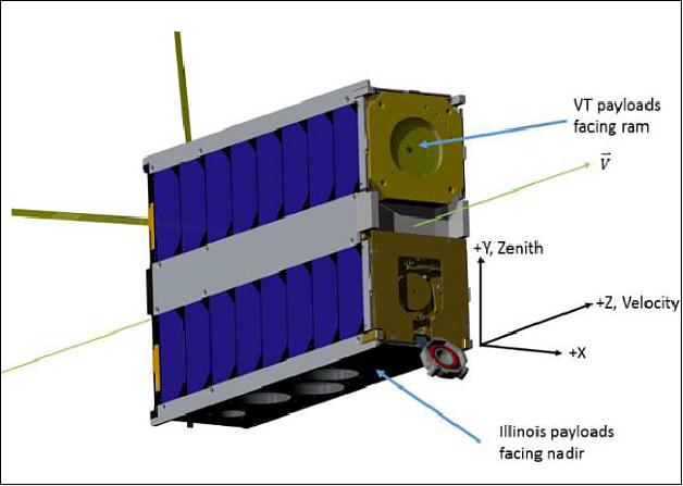
LAICE will fly in a primary science orientation, maintaining the in-situ sensors into the velocity direction, while the photometers will point in a nadir direction. This is shown in Figure 5. The photometer payloads can only operate during orbital night. The remaining payloads can operate during the daytime, however for power preservation reasons, are intended to primarily operate only when the photometers are also operating. Further, the LINAS instrument is particularly power hungry, and is always run at only a 10% duty cycle (Ref. 1).
The three in-situ instruments RPA, LINAS and SNeuPI are provided by Virginia Tech. The overarching objective is to investigate the gravity wave-driven coupling between the terrestrial atmosphere and the lower thermosphere/ ionosphere. In-situ instrumentation will measure the perturbations the waves produce in both neutral and ion densities at F-region heights, while on-board photometers will simultaneously measure the wavelengths and amplitudes of the wave fields in the upper mesosphere. 4)
Photometer Assembly
The photometer assembly is provided by the University of Illinois. The objective is to observe the nighttime airglows. The assembly look direction is toward nadir; it has four photometer channels observing different wavelengths associated with 2 airglow emissions.
To observe gravity waves in the middle atmosphere, remote sensing of mesospheric airglows was selected, which is a well-proven method. The airglow bands selected for observation were O2 Atmospheric (0,0) at 762 nm and O2 Herzberg I at 280 nm which has a broadband UV spectrum. These bands are advantageous for observation from space, as the lower atmosphere is absorptive at these spectra, which minimizes background noise for a nadir-pointed instrument. Also, their band centroids are separated by ~3 km in altitude, enabling a vertical wavelength determination by the phase shift in observed waves.
Horizontal wavelengths are determined by use of a 4-pixel linear array, which is constructed by fiber coupling 4 PMT sensors to one of the O2 A band photometer channels. A background channel at 770 nm will provide a background noise calibration for the O2 A channels. Determination of mesospheric temperatures is accomplished by use of 2 O2 A channels with differing wavelengths (763.5 and 765.5 nm). In all, 4 photometer channels are required for this observation approach.
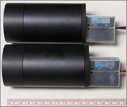
The PMTs (Photomultiplier Tubes) were selected as the sensor based on initial performance analysis of commercially available photo sensors. The specific sensors selected were Hamamatsu PMT modules model H10682-01 (IR channels) and H10682-110 (UV channel), which are COTS (Commercial off the Shelf) sensors that come equipped with most of the power and signal electronics built-in: high-voltage power supply, amplifiers, pulse discriminators and shapers. Selection of these COTS sensors reduced development and test risk vs. custom development, with the tradeoff of requiring space qualification of the COTS sensors.
The optical design of the photometer channels uses a single lens, bandpass filter, field stop, and baffle and utilizes COTS optical tubes. Prototypes are shown below in Figure 6. The designs of the 770 nm and 763.5 nm channels are similar, differing only in tube diameter and focal length. The short baffle is designed to prevent light from Earth's limb to directly impact the last optical element (filter).
RPA (Retarding Potential Analyzer)
The ionospheric ion density and temperature will be measured in-situ via the RPA (Retarding Potential Analysis) technique. Mechanically, an RPA is a series of finely woven wire mesh grids in a stacked planar configuration between an aperture grid and a solid planar collector. The collector and all but one of the grids are held at constant (but different) potentials, and the non-constant retarding voltage (RV) grid voltage is swept over a range of positive values from spacecraft ground potential through about +12 V. The full assembly is depicted in Figure 7.

The suppressor grid must have a large enough negative voltage to prevent secondary and photo electrons from leaving the collector, since these effects would bias the current measurement by artificially enhancing the measured positive collector current. A sufficient value to repel the electrons is -5 V, so the electronics must be able to drive the suppressor grid at or below this level.
The grid voltages are controlled by a four-channel 16 bit DAC (Digital Analog Converter) with an output range of 0-5 V. Each DAC output goes through a simple RC filter to minimize noise on the grids, and then is amplified by factor of 2.4 by a simple non-inverting op-amp (operational amplifier) configuration. This makes the output voltage range 0-12 V for each grid. In addition, the DAC output to the suppressor grid goes through an inverting stage, resulting in a suppressor grid voltage range of 0 to -12 V, surpassing the -5 V requirement.
LINAS (LAICE Ionization gauge Neutral Atmosphere Sensor)
LINAS consists of a Cannon Corp. MG-2M Bayard-Alpert ionization gauge, controller electronics, and associated harnesses. LINAS is primarily based on the IGS (Ionization Gauge Streak) design that was flown on the STREAK satellite mission (launch Sept. 23, 2005) with modifications for the LAICE CubeSat. Modifications include replacement of obsolete parts, removal of unneeded features (stepping voltage, chamber screen), miniaturization of connectors, and a repackaged board for 1U CubeSat form factor. This sensor is based on a hot-filament ionization gauge that is routinely used to make laboratory pressure measurements in vacuum chambers.
The LINAS gage operates by partially ionizing a volume of gas to be measured using a stream of electrons, and then measuring the current resulting from the ions collected by the biased collector. The density of the gas within the chamber/volume is proportional to the ratio of the collected ion current to the ionizing electron current. From the pressure data, the neutral temperature may also be calculated. What makes LINAS a thermospheric sensor and not merely a standard ionization gauge commonly used in laboratories, is the high resolution, high performance measurements made by state-of-the-art electronics. A functional block diagram is shown in Figure 8.
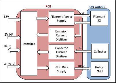
The ionization gauge consists of two Yttria-coated Iridium filaments providing redundancy. The filament emission according to design is 0.4 mA. The supply for the gauge grid potential generates up to 180 V as referenced to the signal ground.
SNeuPI (Space Neutral Pressure Instrument)
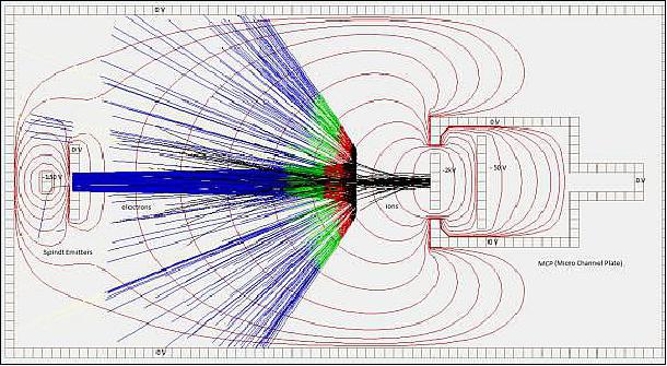
SNeuPI will measure the in-situ upper atmospheric neutral gas density. The instrument is comprised of an aperture, baffle, MCP (Micro-Channel Plate) sensor and a microtip electron emission source (Figure 9) for a depiction of the SNeuPI electron trajectories.
The microtip electron emission source is comprised of a series of Spindt-type field emitters. Each consists of a small sharp molybdenum cone to form a collective large-area field electron source. The emitters form the cathode and a counter-electrode "gate" serves as a grid to shape the electron emission. The emitter tips are driven to a negative potential with respect to the gate. Owing to their sharp apex, the emitter tips create a high electric field at a relatively low voltage.
The Spindt emitter tips are operated at -150 V, while the emitter gate is at ground and the MCP is at -2 kV. With this configuration, electrons which are at approximately 150 eV at the emitter gate, slow down as they approach the MCP.
At a certain distance from the plate, they are repelled and will be absorbed by the walls of the accommodation chamber. It is known that the highest ionization efficiency is in the range of 80-120 eV. It is intended that at these levels, the neutral gas let in through the aperture and the baffle is ionized upon collision. The ions formed will then be attracted to the MCP.
The MCP acts as a multiplier. The current output of the MCP is proportional to the number of ions at its input. Since the number of ions is related to the neutral gas density, this instrument demonstrates an effective method to measure the gas density in the upper atmosphere (Ref. 1).
Payload to bus interface: All payloads receive a dedicated 3.3 V power channel as well as access to the unregulated battery voltage. Each payload is then responsible to appropriately support its specific power requirements using the above. The three in-situ payloads receive their power through a shared set of power lines via a central coordinating the LIIB (LAICE Instrument Interface Board). The photometers similarly share a separate 3.3 V and unregulated power line through a photometer electronics board. Similarly, the in-situ and photometer payloads communicate with the satellite command and data handling through a serial interface implemented over an RS-422.
References
1) Alexander Ghosh, Bindu Jagannatha, Stephen Noel, Greg Earle, Gary Swenson, Kevin Bassett, Rebecca Bishop, Victoria Coverstone, Ryan Davidson, Lucy Fanelli, Chad Fish, Patrick Haddox, Zachary Harlow, Zhe Ji, Erik Kroeker, Tony Mangognia, Peter Marquis, Daniel Martin, Cameron Orr, Robert Robertson, Shimeng Wang, John Westerhoff, "Increasing CubeSat Form Factor to 6U: the Lower Atmosphere/Ionosphere Coupling Experiment," Proceedings of the 65th International Astronautical Congress (IAC 2014), Toronto, Canada, Sept. 29-Oct. 3, 2014, paper: IAC-14-B4.4.10
2) Lynn Nystrom, "Space@Virginia Tech to lead new NSF satellite study to improve communications," May 22, 2013, URL: http://www.eng.vt.edu/news/spacevirginia-tech-lead-new-nsf-satellite-study-improve-communications
3) https://web.archive.org/web/20150923000534/http://isgc.aerospace.illinois.edu/urop/documents/10Coverstone-GhoshLAICE.pdf
4) Gregory Earle, "Collaborative Research: CubeSat--Lower Atmosphere/Ionosphere Coupling Experiment (LAICE)," URL: http://grantome.com/grant/NSF/AGS-1242898
The information compiled and edited in this article was provided by Herbert J. Kramer from his documentation of: "Observation of the Earth and Its Environment: Survey of Missions and Sensors" (Springer Verlag) as well as many other sources after the publication of the 4th edition in 2002. - Comments and corrections to this article are always welcome for further updates (eoportal@symbios.space).
Overview Spacecraft Launch Sensor Complement References Back to Top