Landsat-1 to 3
EO
NASA
Mission complete
RBV
Landsat is the pioneering land remote sensing satellite program, conceived by USGS (United States Geological Survey) and developed by National Aeronautical and Space Administration (NASA) in the United States in 1972. The primary objective was to monitor Earth’s resources via multispectral, high spatial resolution images of solar radiation reflected from Earth’s surface. The first three spacecraft of the series were launched in July 1972, January 1975 and March 1978, respectively, and were decommissioned in January 1978, February 1982 and March 1983, respectively.
Quick facts
Overview
| Mission type | EO |
| Agency | NASA |
| Mission status | Mission complete |
| Launch date | 23 Jul 1972 |
| End of life date | 02 Jan 1978 |
| Instruments | RBV |
| Instrument type | TBD |
| CEOS EO Handbook | See Landsat-1 to 3 summary |
Related Resources
Summary
Mission Capabilities
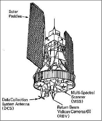
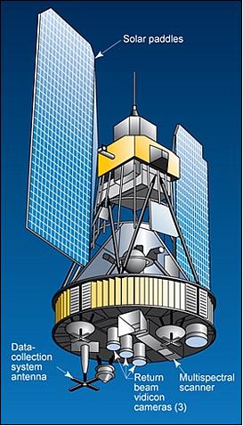
Landsat-1, -2 and -3 each carried three instruments: a multispectral scanner (MSS), a Return Beam Vidicon (RBV) camera and a World Reference System (WRS-1). An experimental Data Collection System (DCS) also flew onboard to collect and retransmit data from remote data collection platforms. Built by SBRC (Santa Barbara Research Centre), the purpose of MSS was to provide repetitive daytime acquisition of high-resolution, multispectral data of the Earth’s surface on a global basis to demonstrate that remote sensing from space is a feasible and practical approach to managing Earth’s resources. MSS employed a whiskbroom scanning method to image in four spectral bands in the visible and near-infrared (VNIR) region. The RBV system was designed and developed at RCA Astro-Electronics Division and consisted of three coaligned television cameras, one for each spectral band (blue-green, yellow-red and near IR). WRS is a global notation system for data processing of the Landsat program, and Landsat-1, -2 and -3 employed the WRS first generation (WRS-1).
Performance Specifications
MSS was capable of imaging eight bands with a spatial resolution of 80 m and a swath width of 185 km. A line array of six detectors positioned in the along-track direction provided an instantaneous parallel along-track coverage of 480 m in one cross-track scan. The RBV system technology became only a secondary observation technology when compared to the MSS systems due to their susceptibility to malfunctions. The MSS whiskbroom scanning technology also proved to be more stable and flexible than the video technology of the RBV system. RBV viewed a ground scene 185 x 185 km in size with 80 m resolution.
Landsat-1, -2 and -3 each occupied a sun-synchronous near-circular orbit at an altitude of 908 km with an inclination of 99°. Each satellite had a period of approximately 103 minutes, a repeat cycle of 18 days and a local equator crossing time at 0945 hours on a descending node.
Space and Hardware Components
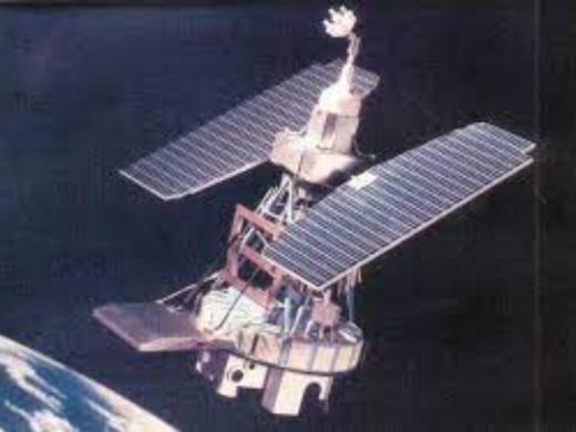
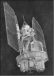
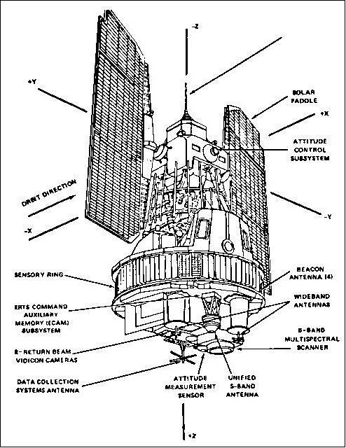
Landsat-1, -2 and -3 were developed as modified versions of the Nimbus spacecraft. Each was 3 m tall and 1.5 m in diameter with twin solar paddles (single-axis articulation) that extended to 4 m with masses of 816 kg, 953 kg, and 960 kg respectively. The three-axis stabilised Earth-oriented platform featured an advanced attitude control system consisting of horizon scanners, sun sensors and a command antenna combined with a Freon gas propulsion system. Nickel-cadmium batteries were used for eclipse phase operations support. Built with a design life of one year, each of the three Landsat spacecraft surpassed their predicted end-of-life date.
Landsat-1 to Landsat-3
Spacecraft Launch Mission Status Sensor Complement References
Landsat is the pioneering US (United States) land remote sensing satellite program which has provided a continuous supply of synoptic, repetitive, multispectral data of the Earth's land surfaces since 1972. Over the years a large international user community evolved along with the Landsat series. The program opened entire new fields of research, providing insights into geologic, agricultural, and land-use surveys, and led eventually to new paths of resource exploration - in all, for a better understanding of the Earth system.
The primary mission objective was to monitor Earth resources with two imaging systems and to achieve periodic and complete coverage of the United States via multispectral, high spatial resolution images of solar radiation reflected from the Earth's surface. Secondary objectives included acquisition of multispectral images over important major land masses other than the United States, at least once per season, and the relay of data acquired by ground based platforms via the Landsat satellite to a central analysis facility to support the modelling of Earth resource oriented processes. 1) 2)
On reflection, the success of the Landsat program stimulated new approaches to data analysis and gave impetus to new sensor designs. In addition international participation was fostered on many levels which spawned other Landsat-like programs such as the SPOT series of France, the Resurs series of Russia, and the IRS series of India. 3) 4) 5)
Spacecraft
The NASA LS-1 (Landsat-1) spacecraft was a modified version of Nimbus-4 bus (built by General Electric), a three-axis stabilized Earth-oriented platform. An advanced attitude control system, consisting of horizon scanners, sun sensors, and a command antenna combined with a Freon gas propulsion system permitted the spacecraft's orientation to be maintained within plus or minus 0.7º in all three axes. Twin solar paddles (single-axis articulation) provided 1000 W (BOL peak), 515 W (BOL average). NiCd batteries were used for eclipse phase operations support. The spacecraft design life was 1 year, but operations continued until Jan. 6, 1976 (3 1/2 years of operations). 6)
In the timeframe of the early 1970s, the spacecraft (LS-1 and LS-2) used an OBC (OnBoard Computer) referred to as APO (Advanced Onboard Processor) and a 4096 word x 18 bit plated wire memory (a simple memory with hard wired logic). 7)
Spacecraft communications: Data were transferred with a 1 W transponder. The S-band and VHF communications system included a command subsystem operating at 154.2 and 2106.4 MHz and a PCM narrow-band telemetry subsystem, operating at 2229.5 and 137.86 MHz, for spacecraft housekeeping, attitude, and sensor performance data. Video data from the three-camera RBV system was transmitted in both real-time and tape recorder modes at 2265.5 MHz, while information from the MSS was constrained to a 20 MHz RF bandwidth at 2229.5 MHz. - Two WBVTR (Wideband Video Tape Recorder) were installed on LS-1 through LS-3. Each WBVTR was capable of recording 30 minutes of either 3.2 MHz video (analog) data from RBV, or 15 Mbit/s digital data from the MSS multiplexer. On LS-1 the WBVTR-1 lasted until July 1974, while WBVTR-2 operated for only 10 days.
It quickly became apparent that the digital image data, acquired by the MSS (Multispectral Scanner) instrument, a whiskbroom scanning device, were of great value for a broad range of applications and scientific investigations. For the first time, the data of an orbiting instrument were available in digital form, quantified at the instrument level - providing a great deal of flexibility by offering all the capabilities of digital processing, storage, and communication. On reflection, the MSS ushered in an era of hitherto unimagined synoptic knowledge of Earth. An extraordinary number of uses for MSS data emerged as data were acquired and disseminated: land-use planning, vegetation inventories, crop growth and health assessments, and cartography, to name a few.
The LS-1 to -3 satellites were all modified Nimbus spacecraft about 3 m tall and 1.5 m in diameter, the solar panels extended to 4 m. The different S/C had the following on-orbit dry masses: LS-1 = 816 kg; LS-2 = 953 kg; LS-3 = 960 kg;
Launch
Launch: A launch of LS-1 took place on July 23, 1972 on a Delta-900 launch vehicle from VAFB (Vandenberg Air Force Base), CA.
Orbit: Sun-synchronous near-circular orbit of LS-1, LS-2 and LS-3, average altitude of 907 to 915 km, inclination of 99º, period of 103 min, repeat cycle of 18 days (251 orbits in cycle), local equator crossing time at 9:45 hours on a descending node (i.e., in north-south direction).
Data: image size: 2583 lines x 5500 pixel (EDIPS format); image size: 2286 lines x 3600 pixel (Telespazio format).
Mission Status
Landsat-1
• January 1978: Landsat-1 was taken out of service after its tape recorders malfunctioned.36)
• July 23, 1972: Landsat-1 (initially named ERTS-A) was launched on a Delta 0900 out of Vandenberg Air Force Base in California. 34)35)
Landsat-2
• March 31, 1983: The satellite was placed in standby mode on.37)
• February 25, 1982: The satellite was removed from operations due to a faulty yaw control thruster.38)
• April 1975: Landsat-2 transmitted its data to several international ground stations. Operations at the ground stations first began in Prince Albert, Canada. 39)
• January 22, 1975: Landsat-2 was launched on a Delta 2910 out of Vandenberg Air Force Base in California. Landsat 2 was originally set to launch on January 19, 1975, but an electrical problem with the launch vehicle caused the launch to be postponed. 38)
Landsat-3
• September 7, 1983: Landsat 3 was decommissioned.41)
• March 31, 1983: The satellite was placed in standby mode.40)
• March 5, 1978: Landsat 3 was launched from Vandenberg Air Force Base, California. Landsat 3's MSS had five spectral bands, however, one failed shortly after launch.40)
Sensor Complement
MSS (Multispectral Scanner)
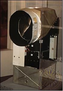
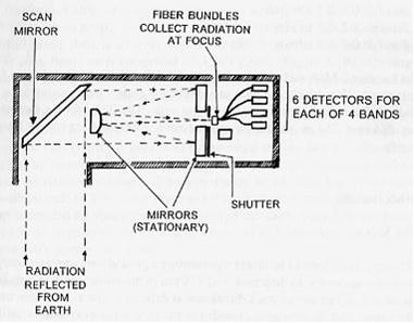
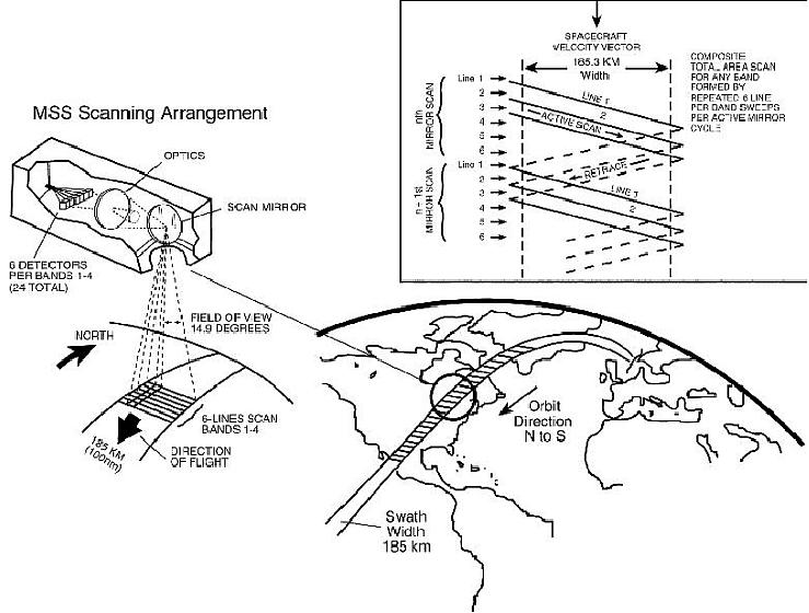
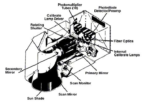
The MSS instrument was built by SBRC (Santa Barbara Research Center) of Hughes and flown on LS 1-5; PIs: Joseph Arlauskas, S. C. Freden. The objective of MSS was to provide repetitive daytime acquisition of high-resolution, multispectral data of the Earth's surface on a global basis and to demonstrate that remote sensing from space is a feasible and practical approach to efficient management of the earth's resources. MSS is an opto-mechanical scanning instrument (whiskbroom technique, unidirectional operation) consisting of a double reflector-type telescope, scanning mirror, filters, detectors, and associated electronics. 12) 13)
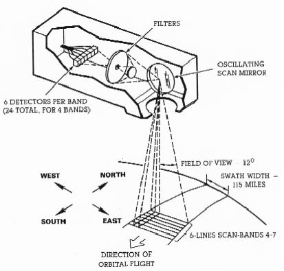
The MSS consisted of an oscillating mirror scanning the ground in the cross-track direction by using six simultaneous line scans (one line scan per detector per spectral band). The sensor operated by repeatedly scanning a 24-element fiber-optic array (arranged in 6 x 4 elements) from west to east across the Earth's surface, the orbital motion provides the natural north-south scanning motion (see Figure 6). A separate binary-number array was generated for each spectral band. Mirror scan rate: 13.6 Hz (74 ms period); telescope: 22.9 cm diameter, f/3.6, Ritchey-Chretien type telescope; size 53 x 58 x 127 cm; six detectors were employed in each of the four spectral bands. Note: the line array of six detectors was positioned in the along-track direction, thus providing an instantaneous parallel along-track coverage of about 480 m in one cross-track scan with the configuration. This wide along-track coverage permitted sufficient integration time for all cells in each scan sweep. Spectral bands 4 to 6 used photomultiplier tubes (PMT) as detectors, and band 7 used silicon photodiodes.
Instrument mass = 64 kg; power = 50 W; data quantization = 6 bit; spatial resolution = 56 m in cross-track and 80 m in along-track direction; swath width = 185 km; four spectral bands: 0.5 - 0.6 µm, 0.6 - 0.7 µm, 0.7 - 0.8 µm, and 0.8 - 1.1 µm; a gray-lamp sensor calibration is performed during every second retrace period of the scan mirror.
A multiplexer included in the MSS system processed the scanner's 24 channels of video data. The data were time-multiplexed and then converted to a pulse-code modulated signal by an A/D converter. The data were then transmitted (2229.5 MHz) directly to an acquisition station or, in the case of remote areas, stored on magnetic tape for subsequent playback the next time the spacecraft came within communication range of an acquisition station. 15)
Note: LS-1-3 orbits were at an average altitude of 908 km while LS-4 and LS-5 orbits were positioned at an altitude of 705 km. For reasons of compatibility the optics of LS-4 and LS-5 were adjusted to keep the spatial (cross-track) resolution at 80 m.
Parameter | Value | Parameter | Value |
Spectral bands (nm) | 500-600, 600-700, 700-800, 800-1100 | Detector arrangement | 6 parallel (along-track) in each of 4 bands |
FOV (swath width) | 11.56º (185 km) | Single-sweep ground track length covered | 480 m (6 x 80 m) |
Spatial resolution (IFOV) | 80 m, 86 µrad (258 µrad for band 8 = 240 m) | Mirror scan rate | 13.6 GHz, (74 ms) |
Detector type | PMT (Photomultiplier) | Telescope type | Ritchey-Chretien |
Telescope aperture | 22.9 cm diameter, f/3.6 | Telescope size | 53 cm x 58 cm x 127 cm |
Instrument mass, power | 64 kg, 50 W | Data quantization | 6 bit |
Channel designation on Landsat S/C | Spectral Range (nm) | |
LS-1 through LS-3 | LS-4 and LS-5 |
|
Channel 4 | Channel 1 | 500 - 600 (green) |
Channel 5 | Channel 2 | 600 - 700 (red) |
Channel 6 | Channel 3 | 700 - 800 (photo-IR) |
Channel 7 | Channel 4 | 800 - 1100 (NIR) |
Channel 8 (channel 8 only on LS-3 for test purposes until July 11, 1978) | 10400 - 12600 (TIR) | |
Note: Starting with LS-4 the MSS bands were renumbered to bands 1 through 4 (from 4 through 7 on LS-1 to 3).
Whiskbroom scanning method employed: The MSS instrument scanned 6 contiguous lines (detector arrays for each band) in parallel with each mirror oscillation resulting in a 1/6 reduction of the scan rate. With 6 x 80 m resolution, this resulted in a 480 m parallel observation coverage in the along-track direction in one scan sweep. The advantage of this parallel detector arrangement resulted of course in much longer dwell (or integration) times for each pixel in the cross-track direction.
Imaging steps of the MSS instrument:
• Unidirectional whiskbroom scanner
• Imaging of the Earth surface in cross-track using an oscillating mirror
• The along-track dimension is provided by the satellite motion in its path
• Six scan lines are being imaged simultaneously; each scan line collects four spectral bands (6-bit resolution)
• The effective instrument IFOV 68 m x 83 m (resolution), a typical scene is 185 km x 185 km.
RBV (Return Beam Vidicon Camera)
The RBV system was designed and developed at RCA Astro-Electronics Div., Princeton, NJ (PI: Oscar Weinstein). This instrument was only flown on LS-1 to LS-3. It consisted of three coaligned television cameras, one for each spectral band (band 1: blue-green, band 2: yellow-red, band 3: near IR). RBV measurements of reflected solar radiation were only conducted in daylight. The three earth-oriented cameras were mounted to a common base, which was structurally isolated from the spacecraft to maintain accurate alignment. Each camera contained an optical lens, a 5.08 cm RBV, a thermoelectric cooler, deflection and focus coils, a mechanical shutter, erase lamps, and sensor electronics. The cameras were similar except for the spectral filters contained in the lens assemblies that provided separate spectral viewing regions. 16)
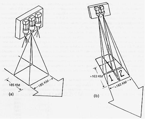
RBV imaged an entire ground scene (frame) instantaneously thereby providing a greater cartographic fidelity than MSS. The viewed ground scene, 185 by 185 km in size (80 m resolution), was stored on the photosensitive surface of the camera tube, and, after shuttering, the image was scanned by an electron beam to produce a video signal output. Each camera was read out sequentially, requiring about 3.5 s for each of the spectral images. The cameras were operated every 25 s to produce overlapping images along the direction of spacecraft motion. RBV contained a "reseau grid" to compensate for image distortions. Video data from the RBV were transmitted (2265.5 MHz) in both real-time and tape recorder modes. The RBV and MSS systems observed simultaneously the same ground swath at nadir of 185 km width. This arrangement provided also a good comparison of the two different observation methods. 17)
Note: A reseau grid is used in the science of photogrammetry for establishing a geometrical basis for measuring objects in photographs. It can be used to correct for any misalignment of the film in the camera, or distortions in the image after development or electronic scanning.
RBV Instrument | |
Spectral bands (µm) | 1) 0.48 - 0.58, 2) 0.58 - 0.68, 3) 0.70 - 0.83 (bands 1 through 3) |
Spatial resolution | 80 m |
Three coaligned cameras | image of 185 km x 185 km (framing cameras) |
Radiometric signal | Analog video signal transmission, 33 dB SNR in bands 1 and 2, 30 dB in band 3 |
MSS Instrument | |
Spectral bands (µm) | 4) 0.5 - 0.6, 5) 0.6 - 0.7, 6) 0.7 - 0.8, 7) 0.8 - 1.1 (bands 4 through 7) |
Spatial resolution | 80 m |
Swath | 185 km (continuous strip image) |
Radiometric signal | Digital video signal transmission; 6 bit per pixel, linear coding;; logarithmic coding also available on bands 4), 5), and 6) |
In the LS-1 mission, the RBV operated only from July 23 1972 to Aug. 5, 1972 when a malfunction occurred. Only 1690 scenes in total were collected. In the LS-2 mission, only occasional RBV imagery was obtained for cartography in remote areas.
DCS (Data Collection System)
DCS was flown on LS-1 through LS-3. Heritage of IRLS (Interrogation, Recording, and Location System- of Nimbus-3). DCS was an experimental system with the objective to collect and retransmit data from remote data collection platforms (DCPs). The onboard DCS serviced initially only a pilot group of only six DCPs, with user agencies procuring, instrumenting, and developing additional platforms according to their needs. The DCP uplink frequency to the Landsat S/C was at 401.55 MHz. The onboard DCS equipment, essentially a receiver, received and retransmitted data (at 2287.5 MHz, DCS data on 1.024 MHz subcarrier) to selected ground receiving stations. There was no signal multiplexing or data processing on the satellite. From a nominal orbital altitude of approximately 900 km, the S/C was capable of acquiring data from DCPs within a radius of approximately 3000 km from the subsatellite point, thus allowing data to be obtained from any remote platform at least once every 12 hours. On LS-1, DCS was operational until January 6, 1978, when the spacecraft was turned off.
Ground Segment
RBV (video) - MSS (scanning) technology comparison
The RBV system technology on LS-1, LS-2 and LS-3 became only a secondary observation technology when compared to the MSS systems due to the following reasons:
• The RBV technology turned out to be much more susceptible to malfunctions than the MSS scanning technique based on solid-state imaging technology. The RBVs were onboard the spacecraft to produce framed images (the conventional approach), whose geometry was more familiar to photogrammetrists. However, the method of RBV camera readout and electronic signal production turned out to be rather complicated. In addition, a separate camera was needed for each spectral band.
• The MSS whiskbroom scanning technology turned out to be much more stable and flexible then the video technology of the RBV system. MSS was the first spaceborne imager in the history of remote sensing capable of producing multispectral data in a digital format. The scan mirror assembly of MSS was in fact the key to providing wide-field and `high-resolution' coverage - in digital form by a simple A/D conversion. The new method was capable of converting incident photons directly into electrical current. In particular, the MSS techniques demonstrated to skeptics that line scanning devices were viable. The new technique of scanning had indeed the promise of more things to come (making imagery quantitatively available to computer processing methods). Thus, on the spaceborne side, MSS (with a cross-track whiskbroom-type scanner) ushered in an era of previously unimaginable synoptic knowledge of the Earth.
Background on MSS: In 1968, SBRC (Santa Barbara Research Center) of Hughes Aircraft Company proposed to NASA to place a new type of imaging device on the planned ERTS spacecraft, namely a "scanner system" in combination with a photodiode detector system. However, at the time, scanners were viewed with great skepticism by most scientists for two reasons. First of all, the scanner employed a moving part, an oscillating mirror, which was considered unreliable. Secondly, the scanner was not a full-frame imaging device; it created images from strips. Cartographers were suspicious of the scanner's geometric integrity.
WRS (World Reference System)
Data from the Landsat satellites is collected in a continuous stream of data along a near vertical path as the satellite moves from north to south in a descending pass. The path/row designation is referred to as the Landsat WRS (Worldwide Reference System). The rows have been positioned in such a way that Row 60 coincides with the equator. This reference system is different for Landsat-1 to -3 and Landsat-4 to -7 because of the different altitudes and inclination angles of the satellites. 18)
WRS is a global notation system for data processing of the Landsat program. WRS enables a user to inquire about satellite imagery (ground coverage in any repeat cycle) over any portion of the world by specifying a nominal scene center designated by PATH and ROW numbers. The WRS has proven valuable for the cataloging, referencing, and day-to-day use of imagery transmitted from the sensors of the Landsat program. 19)
• WRS-1 is being used for the Landsat-1 to -3 mission data. The 18-day ground coverage cycle for Landsat 1-3 is accomplished in 251 orbits. WRS-1 assigns sequential path numbers from east to west to 251 nominal satellite orbital tracks, starting with number 001 for the first track which crosses the equator at 65.48º west longitude.
• WRS-2 is being used for Landsat-4, -5 and -7 mission data (extension to WRS-1). WRS-2 defines Landsat scenes as 185 km x 180 km rectangular areas on the Earth's surface designated by path and row coordinates. The 16-day ground coverage cycle for Landsat 4-7 is accomplished in 233 orbits. Hence, the WRS-2 system is made up of 233 paths numbered 001 to 233, east to west, with Path 001 crossing the equator at 64.60º west longitude.
Some background on the Landsat program
The idea of a civilian Earth resource satellite was conceived by the USGS (United States Geological Survey) of DOI (Department of the Interior) in the mid-1960s. Plans for the first dedicated civil spaceborne Earth-surface imaging project, called EROS (Earth Resources Observation Satellite), were announced at a press conference on Sept. 20, 1966 in Washington, DC. NASA was given the task to plan and build the spacecraft and its payload. NASA launched the newly designated ERTS-1 (Earth Resources Technology Satellite) on July 23, 1972. 20)
• The ERTS program, initiated in 1966, changed its name in 1975 to Landsat. Hence, the former ERTS-1 and ERTS-2 spacecraft were subsequently renamed to Landsat-1 and Landsat-2.
• For LS-1 through LS-3, NASA and USGS shared responsibility for acquiring and distributing the MSS data in the US. The three satellites also transmitted MSS data to international ground receiving stations, sharing the data with much of the world.
• In 1979, the "Presidential Directive 54" under President Jimmy Carter transferred the Landsat operations from NASA, a research and development agency, to NOAA. The directive also recommended development of a long-term operational system with four additional satellites beyond Landsat-3, and recommended transition to private sector operation of Landsat. However, the Landsat system remained a research/experimental NASA program until 1983. The system was then declared as "operational" and its management was turned over to NOAA (LS-4 in 1983 and LS-5 in 1984). Although satellite operations transferred to NOAA, NASA retained responsibility for building and launching Landsat-4 and Landsat-5. 21)
• Commercialization efforts and policies: The Land Remote-Sensing Commercialization Act of 1984 almost immediately authorized a phased commercialization of remote sensing data. This Act authorized the commercial operation of the Landsat satellites under contract to NOAA and with subsidies from the US Government. Following a solicitation and competitive bidding process, NOAA selected the Earth Observation Satellite Company (EOSAT) to operate Landsat-4 and Landsat-5 under a ten year contract. The contract granted EOSAT the exclusive rights to market LS-4 and LS-5 data up to 10 years after the date of data acquisition. EOSAT also received the fees from the international ground stations receiving Landsat data. The contract also assigned EOSAT the responsibility for building, launching, and operating the following two Landsat satellites with government subsidization.
• Some difficulties ensued in the following years of commercial Landsat operations. EOSAT's control over the conditions of data sales were constrained by provisions in the 1984 Act. EOSAT could only sell unenhanced Landsat data to protect the value added vendors and could not provide favorable prices to selected customers in order to ensure nondiscriminatory access to the data. To compensate, EOSAT substantially increased Landsat data prices and severely restricted the redistribution of the data by their customers. Scientists and educators found the data difficult to impossible to afford for research and teaching. Data sales to academic institutions dropped dramatically.
• Following to a contentious commercialization effort, the Land Remote-Sensing Policy Act of October 1992 reversed the 1984 decision to commercialize the Landsat system. The 1992 Policy Act identified the continuity of Landsat data as the fundamental goal of the legislation and created a new "Landsat Program Management" under NASA and DoD leadership. Due to difficulties with the Landsat-7 development program, DoD withdrew from the Landsat Program Management in early 1994.
In spring 1994, the Landsat-7 program was restructured and in May 1994 it was put under joint NASA/NOAA/USGS management by Presidential Decision Directive, with NASA responsible for the development of the LS-7 spacecraft, instrument, and ground system; NOAA is responsible for LS-7 S/C and ground system operations; and USGS responsible for maintaining the national archive of LS data and data distribution to the user community. The EDC (EROS Data Center) of USGS is prime US receiving station of LS-7 data. 22)
Date | Landsat Program Event/Action |
Sept. 21, 1966 | The Department of Interior (DOI) announced that an Earth Resources Observation Satellite (EROS) Program was being initiated to gather data about natural resources from earth-orbiting satellites carrying remote sensing observation instruments. |
July 15, 1968 | An interagency Earth Resources Survey Program Review Committee was established with participation from USDA, USN, ESSA (NOAA), USGS, and NASA |
Aug. 16, 1969 | NASA approved a contract with Hughes Aircraft Company for a multispectral scanner system for ERTS |
June 20, 1969 | NASA approved a contract with RCA Astro-Electronics Division for an ERTS return beam vidicon multispectral three-camera system |
July 15, 1970 | NASA announced its selection of GE as prime contractor (Phase D) for ERTS (contract definitized in May 1971) |
July 23, 1972 | NASA successfully launched ERTS 1 (Landsat-1). |
Jan. 22, 1975 | NASA launched the ERTS-2 spacecraft (LS-2) |
Oct. 20, 1975 | NASA awarded RCA a contract for the return beam vidicon for Landsat C (LS-3), which would have twice the resolution of earlier instruments |
March 5, 1978 | NASA successfully launched Landsat-3 |
July 16, 1982 | NASA successfully launched Landsat-4 |
Mar. 1, 1984 | NASA launches LS-5, NOAA provides LS-4 and LS-5 operation |
Sept. 1985 | Eosat (a partnership of Hughes Aircraft and RCA) was selected by NOAA to operate the LS system (LS-4 and LS-5), to market LS data, and to build and launch LS-6 |
Sept. 1992 | Eosat loses capability of processing MSS data (no further acquisition of MSS in USA) |
Oct. 1992 | Land Remote Sensing Policy Act (Congress) LS program management under NASA and DoD (develop and launch LS-7) |
Oct. 1992 | DoD signs contract with Martin Marietta Astro Space to build HRMSI for LS-7 |
Oct. 5, 1993 | LS-6 launch failure |
Spring 1994 | DoD withdraws from the LS program (HRMSI is withdrawn from LS-7) |
April 1994 | LS program management and Eosat agree for continued operation of LS-4 and LS-5 |
Aug. 10, 1994 | Management Plan for the Landsat Program (LS-7 objectives and beyond). LS program responsibilities are with NASA (S/C), NOAA (operations), and USGS (archive) |
Dec. 1994 | NOAA and Eosat sign a contract to extend LS-5 operation |
Nov. 1995 | Eosat completed maneuvers to correct the equatorial crossing time of LS-5 (to 9:30 AM) |
1998 | By 1998, the management of the Landsat-4 (and Landsat-5) operations contract was transferred from NOAA to the USGS; however, operations were continued by the private sector until July 1, 2001 when Space Imaging (formerly EOSAT) returned the operations contract to the U.S. Government. |
July 23, 2002 | 30th anniversary of Landsat observation program in orbit |
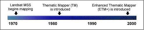
The Landsat satellite family is managed and procured by NASA [built by GE Astro Space of East Windsor, NJ (S/C), and Raytheon Santa Barbara Remote Sensing, formerly a Hughes Santa Barbara Research Center Division. (sensors)]. In 1985 the functions of Landsat S/C operation and data handling were handed over from NOAA to a commercial contractor company: Eosat (Earth Observation Satellite Company, of Lanham, MD; Eosat is a Division of Lockheed Martin Space Imaging. The science data (of LS-4 and LS-5) are processed and archived by Eosat and commercially distributed. The LS-4 and LS-5 S/C and sensors are regarded as second generation technology in the LS program, following the early MSS (Multispectral Scanner) sensor series. The MSS instrument was flown for the last time on LS-5; LS-7 carries an improved Thematic Mapper sensor known as the Enhanced Thematic Mapper Plus (ETM+). 24) 25)
Application: Land use, agriculture, forestry, geology, water resources, mapping, etc. Landsat data are particularly suited to long-term estimation and monitoring of standing vegetation biomass, biological productivity, and the movement of fragile ecosystem boundaries.
The purchase of Landsat imagery became rather expensive to the user community with S/C operations and data distribution in the hands of Eosat. NOAA and Eosat agreed in November 1990 that all Landsat data older than 10 years return to the "Public Domain" category, hence affordable for research. The "Public Domain" data is provided and distributed by the EROS Data Center (EDC), Sioux Falls, S D. All MSS data is in the public domain at EDC, effective as of February 1993.
Orbit for LS-1 to LS-3: Sun-synchronous polar orbit (AM Orbit), altitude = 907- 915 km, inclination = 99.2º, period = 103 minutes, repeat coverage = 18 days, equator crossing time at 9:42 hours on descending node.
Orbit for LS-4 and LS-7: Sun-synchronous polar orbit (AM Orbit), altitude = 705 km, inclination = 98.2º, period = 99 minutes, repeat coverage = 16 days, nominal equator crossing time at 9:45 hours on descending node.
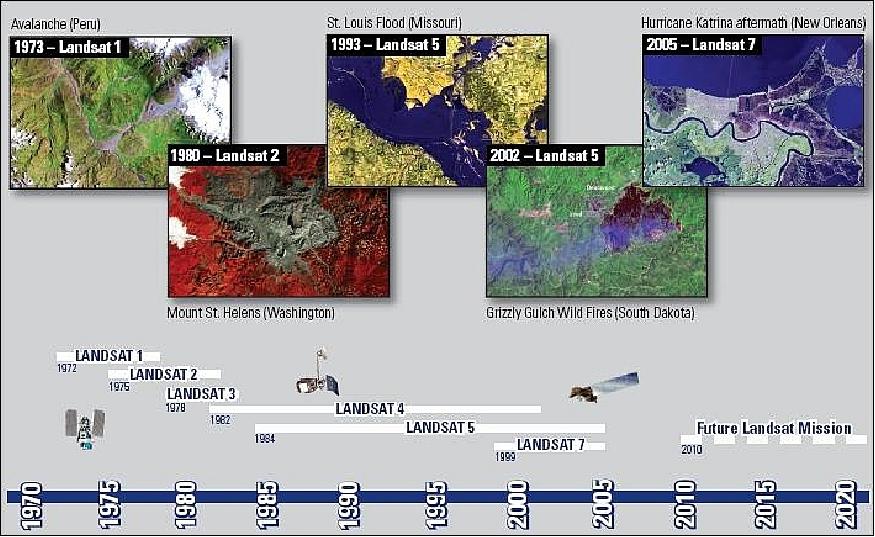
S/C | S/C Launch | Sensor | Data | Data Communications | Orbital | S/C | Revisit Time (days) | Data Rate |
LS-1 (ERTS-1) | Jul. 23, 1972 | RBV | 80 | DD (Direct Downlink) | 907 km | NASA | 18 | 15 |
LS-2 | Jan. 22, 1975 | RBV | 80 | DD with | 908 km | NASA | 18 | 15 |
LS-3 | Mar. 5, 1978 | RBV | 30 | DD with | 915 km | NASA | 18 | 15 |
LS-4 | Jul. 16, 1982 | MSS | 80 | DD | 705 km | NOAA ('83) | 16 | 85 |
LS-5 | Mar. 1, 1984 | MSS | 80 | DD | 705 km | NOAA ('84) | 16 | 85 |
LS-6 | Oct. 5, 1993 | ETM | 15 (PAN) | DD with recorders | launch failure | 85 | ||
LS-7 | Ap. 15, 1999 | ETM+ | 15 (PAN) | DD with recorders | 705 km | NOAA | 16 | 150 |
In 2002, the Landsat program had its 30th anniversary of providing satellite remote sensing information to the world; indeed a record history of service with the longest continuous spaceborne optical medium-resolution imaging dataset available anywhere. The imagery has been and is being used for a multitude of land surface monitoring tasks covering a broad spectrum of resource management and global change issues and applications.
The future
In view of the outstanding value of the data to the user community as a whole, NASA and USGS were working together (planning, rule definition, forum of ideas and discussion among all parties involved, coordination) on the next generation of the Landsat series satellites, referred to as LDCM (Landsat Data Continuity Mission). The overall timeline foresaw a formulation phase until early 2003, followed by an implementation phase until 2006. The goal was to acquire the first LDCM imagery in 2007 - to ensure the continuity of the Landsat dataset (185 km swath width, 5 m resolution and a new set of spectral bands). Overall science objectives of LDCM are: 26) 27) 28) 29) 30) 31)
However, the fate of the Landsat program extension became rather uncertain in Sept. 2003 when NASA rejected the proposal of Resource21 LLC of Englewood, CO to build and operate the LDCM spacecraft. This was the only bid submitted in response to the LDCM request for proposals. 32)
After a long period of uncertainty in program continuity prospects, a solution was reached in early 2007. The plans are to launch LDCM in 2011. NASA and USGS share the responsibility for LDCM. NASA will procure and/or develop the satellite, instrument, launch services and perform on-orbit satellite checkout. The USGS will develop and implement the ground station network, archive and image processing facilities and conduct satellite operations, data archiving and product dissemination. In addition, the USGS will be responsible for satellite flight operations. 33)
In January 2007, an RFP (Request for Proposal) was released by NASA for OLI (Operational Land Imager).
References
1) http://landsat.gsfc.nasa.gov/about/landsat1.html
2) Goddard Space Flight Center NASA. URL: [web source no longer available]
3) Special Issue: 25th Anniversary of Landsat, PE&RS Vol. LXIII, No. 7, July 1997, pp. 829-905
4) Ames Research Center NASA. URL: [web source no longer available]
5) "The Good ERTS," Time Magazine of Nov. 13, 1972, URL: http://www.time.com/time/magazine/article/0,9171,910465-2,00.html
6) NASA Jet Propulsion Laboratory (JPL). URL: [web source no longer available]
7) J. G. Lesko Jr., "Landsat 2 on-board computer," Proceedings of the International Telemetering Conference, Washington, D.C., October 14-16, 1975, (A76-42801 21-32) Pittsburgh, PA, Instrument Society of America, 1975, pp. 400-408
8) CIRA - Cooperative Institute for Research in the Atmosphere. URL: [web source no longer available]
9) Steven J. Covington, Thomas R. Hill, "Maintaining the Legacy of Landsat," Crosslink, The Aerospace Corporation Magazine, Vol. 9, No 2,Winter 2008/2009, URL: http://www.aero.org/publications/crosslink/winter2008/03.html
10) "The Island Named After a Satellite," NASA Earth Observatory, 23 October 2019, URL: https://earthobservatory.nasa.gov/features/videos/landsat-island
11) "The Island Named After a Satellite," NASA Earth Observatory, Image of the day for 10 April 2018, URL: https://earthobservatory.nasa.gov/images/91972/the-island-named-after-a-satellite
12) S. C. Freden, F. Gordon, "Landsat Satellites," Chapter 12 of `Manual of Remote Sensing,' 2nd edition, Vol I, published by the American Society of Photogrammetry, 1983, pp. 517-570
13) A. M. Mika, "Three Decades of Landsat Instruments," PE&RS, July 1997, pp. 839-852
14) https://web.archive.org/web/20100409022338/http://www.nasm.si.edu/research/ceps/rpif/landsat/Landsat.html
15) http://nssdc.gsfc.nasa.gov/database/MasterCatalog?sc=1972-058A&ex=2
16) "Return Beam Vidicon (RBV) panchromatic two-camera subsystem for LANDSAT-C," Final Report RCA Astro-Electronics Div., Princeton, NJ, June 1977
17) http://nssdc.gsfc.nasa.gov/database/MasterCatalog?sc=1972-058A&ex=1
18) http://www.geoimage.com.au/geoweb/pdfs/flyers/LANDSAT_flyer.pdf
19) http://landsat.gsfc.nasa.gov/about/wrs.html
20) S. Goward, T. Arvidson, D. Williams, J. Faundeen, J. Irons, S. Franks, "Historical Record of Landsat Global Coverage: Mission Operations, NSLRSDA, and International Cooperator Stations," PE&RS (Photogrammetric Engineering & Remote Sensing), Vol. 72, Oct. 2006, pp. 1155-1168
21) J. R. Irons, "The Present and Future of the Landsat Program," 2000, URL: [web source no longer available]
22) E. J. Sheffner, "The Landsat Program: Recent History and Prospects," PE&RS, Vol. 60,, 1994, pp. 735-744
23) https://web.archive.org/web/20230421132208/https://history.nasa.gov/SP-4012/vol3/table4.161.htm
24) Monitoring Earth's Ocean, Land, and Atmosphere from Space, Volume 97, AIAA, 1985, Chapter 3
25) A. F. Goetz, J. B. Wellman, W. L. Barnes, "Optical Remote Sensing of the Earth," Proceedings of the IEEE, Vol. 73, No. 6, June 1985, pp. 950-969
26) Landsat Data Continuity Mission (LDCM) NASA, URL: [web source no longer available]
27) U.S. Geological Survey, Landsat Data Continuity Mission (LDCM), URL: [web source no longer available]
28) "Operational Land Imager Requirements Document, Landsat Data Continuity Mission (LDCM)," Revision Draft, Nov. 2, 2006, GSFC, URL: [web source no longer available]
29) J. D. McCuistion, C. D. Wende, J. R. Irons, "Landsat Data Continuity Mission: Creating a Unique Government-Industry Partnership for Global Research," Proceedings of IGARSS 2003, Toulouse, France, July 21-25, 2003
30) J. R. Irons, N. J. Speciale, et al., "Data Specifications for the Landsat Data Continuity Mission," Proceedings of IGARSS 2003, Toulouse, France, July 21-25, 2003
31) http://prod.nais.nasa.gov/eps/eps_data/102577-SOL-001-005.pdf
32) Space News Sept. 29, 2003
33) NASA Goddard Space Flight Center, URL: [web source no longer available]
34) https://web.archive.org/web/20170205002004/https://landsat.usgs.gov/landsat-1-history
35) https://web.archive.org/web/20041118074722/https://history.nasa.gov/SP-4012/vol3/table1.33.htm
36) https://web.archive.org/web/20161228020505/http://astronautix.com/l/landsat1-2-3.html
37) https://web.archive.org/web/20160428104809/http://landsat.usgs.gov/about_landsat2.php
38) https://web.archive.org/web/20170327170533/https://landsat.gsfc.nasa.gov/landsat-2/
39) https://landsat.usgs.gov/historical-international-ground-stations/
40) https://web.archive.org/web/20160412202239/http://landsat.usgs.gov//about_landsat3.php
41) https://nssdc.gsfc.nasa.gov/nmc/spacecraft/display.action?id=1978-026A
Spacecraft Launch Mission Status Sensor Complement References Back to top