LEAP (Low-frequency Earthquake Precursor)
EO
Cancelled
Gravity and Magnetic Fields
Gravity, Magnetic and Geodynamic measurements
Quick facts
Overview
| Mission type | EO |
| Mission status | Cancelled |
| Measurement domain | Gravity and Magnetic Fields |
| Measurement category | Gravity, Magnetic and Geodynamic measurements |
| Instruments | GPS receiver |
| Instrument type | Gravity instruments |
LEAP (Low-frequency Earthquake Precursor) Microsatellite
LEAP is an earthquake precursor research mission of the National Cheng Kung University (NCKU) of Tainan, Taiwan. The goal is to detect the ULF emission in space to confirm postulations on the correlation between the presence of ELF/ULF (Extremely Low Frequency/Ultra Low Frequency) signals and earthquake activities so as to pave a way for a possible earthquake detection method. Taiwan is in the earthquake hotspot region and has previously encountered several major earthquakes including the Chi-Chi (M=7.5) earthquake in September 1999. 1)
Similar satellite missions, such as the DEMETER (CNES) and QuakeSat (Stanford University) satellites, are being flown with instrumentation to detect the ULF/ELF signals in space. The main significance of the LEAP project lies in the ULF range signal which is lower than DEMETER (VLF) and QuakeSat (ELF). The other significance for the LEAP mission is the near equatorial orbit, providing an Earth magnetic filed observation rather than synchronized orbits of QuakeSat and DEMETER. In addition, some analysis capability is built into the onboard digital processor of the LEAP spacecraft to track the variation of ELF/ULF signal frequency. 2) 3)
The LEAP project intends to serve as a testbed by utilizing several subsystem/payload techniques developed and fabricated in Taiwan. These domestic components include GPS receiver software, a MEMS-based digital sun sensor, and a high frequency communication experiment payload.
Spacecraft
The LEAP microsatellite includes the satellite bus, and the sensor complement (payload). The satellite bus (Figure 1) consists of six subsystems: power (EPS), structure (SMS), telecommunication (TT&C), onboard computer (C&DH), thermal control (TCS), and attitude control (ADCS). The spacecraft bus has inherited some features from PACESat (Platform for Attitude Control Experiment Satellite), a former nanosatellite project (2 kg) that has been conducted at National Cheng Kung University. 4)

The SMS (Structure and Mechanical Subsystem) is an aluminum box (7075 T6), a cube of ~ 30 cm side length. The ULF payload (red box) is positioned on top of the satellite body. The TCS (Thermal Control Subsystem) adopts an NCKU self-fabricated MEMS experiment as temperature sensors. The system adopts MINCO patch heaters as active control devices. Sensors are positioned on several components to measure the temperature fluctuations. The spacecraft has a launch mass of 30 kg.
The internal spacecraft configuration is illustrated in Figure 3 showing the various components. A gravity gradient boom is centered into the middle of the structure. The –Z face is equipped with the tip, GPS antenna and solar cells. Two deployable solar panels are folded on the +X and –X faces.
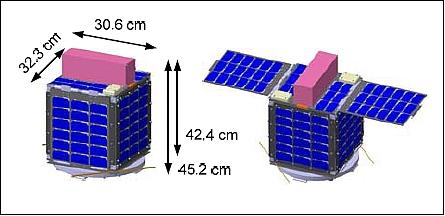
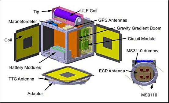
The spacecraft is 3-axis stabilized. The ADCS (Attitude Determination and Control Subsystem) provides active (magnetic coils) and passive control hardware (gravity gradient boom). The gravity gradient boom is comprised of 14 tubular elements with total deployed length 2.94 m. The material of the boom is aluminum. A spring mechanism is used to deploy the boom (Figure 5). In the deployment process, the ULF coil will be moved from the top of the spacecraft to the top of the extended boom.
The block diagram of the ADCS is shown in Figure 4. The magnetometer can provide the magnetic field value in the body frame. The data from the magnetometer can be used directly as the feedback of the magnetic control law to detumble the satellite. The am-meter can detect the current of solar cells of each phase to distinguish the illuminated phases from the dark phases. The current value may contain some attitude information which can determine the timing to deploy the boom (Figure 5).
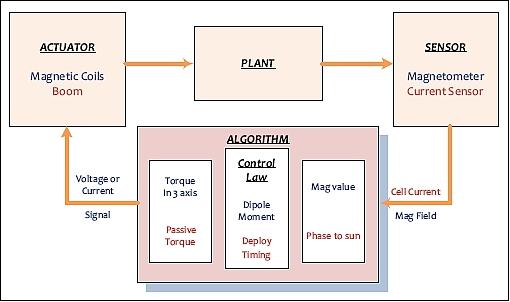
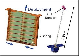
Attitude is sensed with a Honeywell 2300 digital magnetometer, solar panel current detection, as well as aiding information from GPS and the DSS (Digital Sun Sensor) payloads. The spacecraft pointing accuracy is in the range of < 5º. 5)
The EPS (Electrical Power Subsystem) is comprised of surface-mounted solar cells (Emcore), batteries (Li-ion) and the DRU (Distribution and Regulation Unit). An average on-orbit power of 19.8 W is being provided. The C&DH (Command and Data Handling Subsystem) employs a COTS device consisting of CPU, DIO (Digital Input Output), ADC (Analog Digital Converter), and DAC (Digital Analog Converter). About 1.4 MByte of data are being generated per orbit.
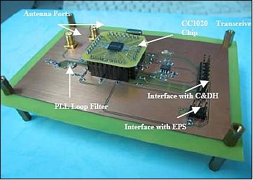
RF communications: A COTS TT&C transceiver module (with contact and beacon modes) is being used in the amateur radio band (UHF, 430 MHz) with a downlink data rate of 9.6 kbit/s. Continuous beacon signals (Morse signal broadcast) are being sent in the ground segment (to reach the NCKU ground station as well as the amateur community). The telemetry data is formatted according to the AX.25 protocol. The onboard TT&C subsystem also receives the telecommand data from the ground during station passes.

Launch
A launch of LEAP microsatellite as a secondary payload was initially planned for the period 2010/11. While the LEAP development has been completed, the spacecraft will not be launched due to budgetary problems by the LEAP project. 6)
Sensor Complement
The satellite payload includes a ULF payload for earthquake precursor research, a GPS payload experiment, a DSS (Digital Sun Sensor) payload for attitude control usage and an ECP (Experiment of Communication Payload) for the high frequency communication experiment.
ULF (Ultra Low Frequency) Sensor
The device is positioned in the tip of the gravity gradient boom. The objective is to measure the Earth's magnetic field in ultra-low frequency range. ULF consists of a search coil, a calibration coil and an amplifier/filter circuit. The search coil is of 20 cm length, a diameter of 5 cm, and a mass of 2 kg with a sampling rate of 10 Hz. The magnetic field is measured at a rate of 0.03 to 3 Hz. The ULF sensor is being operated continuously throughout the mission.


GPS Receiver
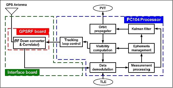
The GPS receiver payload includes a processor, a RF board with RF/correlator IC, antenna, interface circuits, and GPS software. The software consists of orbit propagator, Kalman filter, tracking loop control, visibility computing, ephemeris management, data demodulation and measurement processing. The payload produces position, velocity and time as output to the C&DH.
DSS (Digital Sun Sensor)
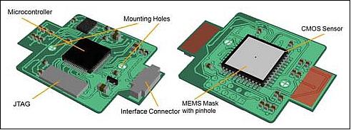
The MEMS-based device is a 2-axis instrument, developed by the LEAP team, using a domestic off-the-shelf (COTS) CMOS APS sensor. DSS includes an image sensor chip as the focal plane, a pinhole mask placed in front of it at a certain distance, an AD converter and a separate data processing unit to compute the sun vector, and to communicate with the C&HD. The sensor will support the ADCS for flip recovery operation. 7)
ECP (Experiment of Communication Payload)
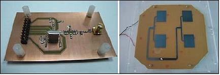
An onboard S-band (2.4 GHz) transmitter is being implemented (in addition the the RF communication system). The objective is to transmit real-time science data during station passes. The ECP device includes a transceiver module with four patch antennas mounted on the Earth-facing side of the spacecraft. ECP serves as an experimental payload with a downlink science data rate of 19.2 kbit/s. With sufficient power available, it will be operated in parallel with the main TT&C system.
References
1) Jyh-Ching Juang, Jiun-Jih Miau, Yi-Yin Liu, Bo-Chang Chen, “Overview of the LEAP: A University MicroSatellite Program at NCKU,” URL: http://satellite.ncku.edu.tw/Publications/eabs_leapoverview.pdf
2) Jyh-Ching Juang, Jiun-Jih Miau, Yi-Yin Liu, Bo-Chang Chen, “Earthquake Research from Space: LEAP Microsatellite Design in Taiwan,” Proceedings of the Asian Space Conference 2007, Nanyang Technological University (NTU), Singapore, March 21-23, 2007
3) Jyh-Ching Juang, Yung-Fu Tsai, Jiun-Jih Miau, “Status Update of the LEAP Microsatellite,” The Fourth Asian Space Conference 2008, Taipei, Taiwan, October 1-3, 2008, URL: http://www2.nspo.org.tw/ASC2008/4th%20Asian%20Space%20Conference%202008/oral/S11-06.pdf
4) Chuen-Feng Hu, Shao-Tai Lu, S. T. Jenq, Jyh-Ching Juang, Jiun-Jih Miau, “Analysis and Design of the LEAP Structure System,” The Fourth Asian Space Conference 2008, Taipei, Taiwan, October 1-3, 2008, URL: http://www2.nspo.org.tw/ASC2008/4th%20Asian%20Space%20Conference%202008/oral/S12-04.pdf
5) K. N. Wang, J. C. Juang, Y. F. Tsai, "Design and Verification of the LEAP Attitude Control System" Proceedings of the. 7th Asian Control Conference , Hong Kong, China, Aug. 27-29, 2009
6) Information provided by Jyh-Ching Juang of NCKU of Tainan, Taiwan (March 14, 2012)
7) Artur Scholz, J. J. Miau, J. C. Juang, “Miniature Digital Sun Sensor for Application in Nano- and Picosatellites,” 2008 CubeSat Developers Workshop, San Luis Obispo, CA, USA, April 9, 2008, URL: http://mstl.atl.calpoly.edu/~workshop/archive/2008/Spring/Day%201/1330%20-%20Scholz%20-%20Digital%20Sun%20Sensor.pdf
The information compiled and edited in this article was provided by Herbert J. Kramer from his documentation of: ”Observation of the Earth and Its Environment: Survey of Missions and Sensors” (Springer Verlag) as well as many other sources after the publication of the 4th edition in 2002. - Comments and corrections to this article are always welcome for further updates (eoportal@symbios.space).