Meteor-M-1 Mission
EO
Ocean colour instruments
Atmosphere
Ocean
Quick facts
Overview
| Mission type | EO |
| Agency | ROSKOSMOS, ROSHYDROMET |
| Mission status | Mission complete |
| Measurement domain | Atmosphere, Ocean, Land, Gravity and Magnetic Fields, Snow & Ice |
| Measurement category | Cloud type, amount and cloud top temperature, Liquid water and precipitation rate, Atmospheric Temperature Fields, Cloud particle properties and profile, Ocean colour/biology, Aerosols, Multi-purpose imagery (ocean), Radiation budget, Multi-purpose imagery (land), Surface temperature (land), Vegetation, Albedo and reflectance, Gravity, Magnetic and Geodynamic measurements, Surface temperature (ocean), Atmospheric Humidity Fields, Sea ice cover, edge and thickness, Snow cover, edge and depth, Ocean surface winds |
| Measurement detailed | Cloud top height, Ocean imagery and water leaving spectral radiance, Ocean chlorophyll concentration, Precipitation intensity at the surface (liquid or solid), Aerosol optical depth (column/profile), Cloud type, Color dissolved organic matter (CDOM), Cloud imagery, Aerosol Extinction / Backscatter (column/profile), Cloud liquid water (column/profile), Land surface imagery, Upward long-wave irradiance at TOA, Aerosol effective radius (column/profile), Fire fractional cover, Earth surface albedo, Magnetic field (scalar), Magnetic field (vector), Short-wave Earth surface bi-directional reflectance, Land cover, Atmospheric specific humidity (column/profile), Atmospheric temperature (column/profile), Land surface temperature, Sea surface temperature, Wind vector over sea surface (horizontal), Ocean suspended sediment concentration, Sea-ice cover, Snow cover, Wind speed over sea surface (horizontal), Normalized Differential Vegetation Index (NDVI), Sea-ice thickness, Sea-ice type, Height of tropopause, Diffuse attenuation coefficient (DAC) |
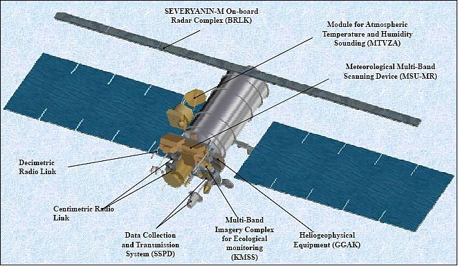
| Instruments | DCS, KMSS, MTVZA-GY, MSU-MR, SCAT-M3, GGAK-M, Severyanin-M, ARMA-M3, MSU-O, CZS |
| Instrument type | Ocean colour instruments, Imaging multi-spectral radiometers (vis/IR), Space environment, Scatterometers, Imaging multi-spectral radiometers (passive microwave), Data collection, Imaging microwave radars, Atmospheric temperature and humidity sounders |
| CEOS EO Handbook | See Meteor-M-1 Mission summary |
Meteor-M-1
Overview Spacecraft Launch Mission Status Sensor Complement Ground Segment References
The Meteor-M-1 (also referred to as Meteor-M N1) satellite is a Roskosmos/Roshydromet/Planeta (Moscow, Russia) follow-up polar-orbiting meteorological mission to Meteor-3M-1 (launch Dec. 10, 2001). The organization responsible for the acquisition, recording, processing, archiving, cataloging, and dissemination of space data is NTs OMZ (Research Center for Earth Operative Monitoring), Moscow.
The overall objectives of the Meteor-M-1 mission are to provide operational meteorological services: 1)
1) To acquire multispectral imagery in the visible range as well as radar imagery of the Earth's surface and to obtain measurements of the Earth-atmosphere system in various bands of the energy spectrum in terms of absolute energy values
2) To acquire information of the Sun-Earth system (solar wind parameters)
3) To perform a data collection function from independent measuring platforms in the ground segment.
The data acquired from the Meteor-M spacecraft is being used to solve the following main tasks:
• Regional and global weather analysis and prediction, including climate and global change monitoring
• Analysis and prediction of ocean surface-water states
• Analysis and prediction of the space weather (solar wind, ionospheric interaction, Earth's magnetic field, etc.).
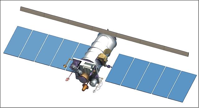
Spacecraft
The spacecraft platform used is being built by VNIIEM of Moscow as prime contractor to Roskosmos. It's heritage is of the Resurs-O1 spacecraft series and is now being referred to as Resurs-USP. The spacecraft is three-axis stabilized. Attitude sensing is being provided with a star tracker, referred to as BOKZ-M. The S/C pointing accuracy is 0.1º, the angular drift rate is 0.0005º/s. A navigation subsystem (GPS/GLONASS receiver) provides orbit determination and timing services.
The BOKZ-M star tracker is of Resurs-DK1 (launch June 15, 2006) heritage. The BOKZ family instrument is a monoblock with the digital TV camera based on a CCD array detector, a signal processor based computer and a secondary power supply unit. The instrument is providing a pointing accuracy of 2 / 20 arcsec (x, y / z), the attitude data is updated at a frequency of 0.3 Hz, the instrument has a mass of 4 kg, power consumption of 11.2 W, and a size of 37 cm x 23 cm x 23 cm.
Solar power of 2 kW (BOL) is provided by two deployed panels which are continuously sun pointed for optimum power generation (solar panel area of 23 m2, solar array span of 14 m).
The S/C mass is ~ 2900 kg (payload mass of ~ 1250 kg). The S/C design life is 5 years with a goal of additional service provision. 2) 3) 4) 5)
RF communications: Use of LRIT (Low Rate Information Transmission) and HRIT (High Rate Information Transmission) communication standards according to WMO (World Meteorological Organization) to permit data exchange on an international level.
1 | X-band data transmission | 8025-8400 MHz |
| Nominal carrier frequency | 8128 (T1); 8320 (T2) MHz |
| Data transmission rate | 15.36, 30.72, 61.44, or 122.88 Mbit/s |
| Transmitter output power | 10 W |
| Data modulation type | RFM, DRFM (Digital Radio Frequency Memory) |
2 | L-band data transmission | 1.69 - 1.71 GHz |
| Nominal carrier frequency | 1.7 GHz |
| Data transmission rate | 665.4 kbit/s |
| Transmitter output power | 5 W |
| Modulation type | PSK (Phase-Shift Keying) |
3 | VHF-band data transmission | 137-138 MHz (MSU-MR bands in LRPT format) |
4 | Onboard data collection and transmission system from DCPs (Data Collection Platforms) | |
| No of DCPs in visibility zone, common | 150, < 500 |
| Message volume | 250 bit |
| Data transmission rate | 1200 or 400 bit/s |
| Location accuracy of DCP | 3.6 km (for one session) |
| Total volume of stored data for one orbital revolution | 300 kByte |
| Data reception frequency from DCPs | 401.2-402.0 MHz (UHF band) |
| Data transmission from S/C to ground | 1690-1710 MHz (L-band) |
Launch
The Meteor-M-1 spacecraft was launched on Sept. 17, 2009 on a Soyuz-2.1b/Fregat vehicle from Baikonur in Kazakhstan. -- The mission was initially planned to be launched in 2007 but was postponed several times.
The six secondary payloads on this flight were: 6) 7)
• Tatiana-2, also spelling of Tatyana-2 (Universitetskiy, 100 kg), a microsatellite of the Lomonosov Moscow State University (MSU), Moscow
• Sterkh-2 (a microsatellite of ~ 171 kg), will serve as Cospas-12 in the COSPAS-S&RSAT search & rescue network.. Sterkh-2 was built by PO Polyot.
• UGATUSat (a microsatellite of 30 kg) of Ufa State Aviation Technical University (UGATU), Russia, built by PO Polyot.
• ZASat-002 (SumbandilaSat, a microsatellite of 82 kg) of SunSpace, South Africa.
• BLITS (Ball Lens In the Space), a nanosatellite of 7.53 kg (sphere, reflector). BLITS was developed and manufactured by the IPIE center, under a 2006 agreement between Roskosmos and International Laser Ranging Service (ILRS). The purpose of the mission is experimental verification of the spherical glass retroreflector satellite concept.
• IRIS , an experimental unit attached to the Fregat upper stage, built be NPO Lavochkin and designed to test an inflatable and solidifying material in space.
Note: The Fregat upper stage can deliver only an even number of piggyback satellites.
Orbit: Sun-synchronous near-circular orbit, mean altitude of 832 km, inclination = 98.85º, period of 101.3 minutes, local equatorial crossing time at 12:00 hours.
Note: The launch vehicle placed the ZA-002/SumbandilaSat spacecraft into an orbit of 510 km altitude.
Mission Status
• April 2014: The Meteor-M1 spacecraft is still operated by Roshydromet; however, with limitations due to some instruments failures. The current status of the basic instruments: 8)
- MSU-MR instrument is functional with limitations (calibration issues and large noise level in the IR channels)
- MTVZA-GY instrument is functional with limitations due to failures of on-board memory and atmospheric sounding channels
- KMSS instrument is fully functional
- Severjanin instrument is non-operational
- DCS is functional with limitations due to interferences to signals from ground sources
- LRPT transmission is functional with limitations due to information compression errors
- GGAK-M is operational with significant limitations.
• In 2012, the Meteor-M1 spacecraft and its payload are operating nominally. 9)
• In the spring of 2010, the Meteor-M-1 spacecraft status is referred to as 'experimental operation.' 10)
• October 7, 2009: during flight testing of the spacecraft Meteor-M-1, the GGAK-M heliogeophysical complex was switched on by NTs OMZ. The GGAK-M equipment operated nominally.
• The first switching on of onboard equipment on the Meteor-M-1 spacecraft was carried out on Oct. 1 and 2, 2009. Reception and processing of KMSS imagery was carried out at NTc OMZ of Roskosmos, which operates the spacecraft Meteor-M-1. 11)
• Sept. 23, 2009: The Meteor-M-1 spacecraft is in the early checkout phase. 12)
Sensor Complement
MSU-MR (Low-resolution Multispectral Scanner)
MSU-MR was designed and developed by FSUE/RISDE (Federal State Unitary Enterprise) / Russian Scientific Institute of Space Device Engineering), Moscow. Objective: Global and regional cloud cover mapping, SST (Sea Surface Temperature), and LST (Land Surface Temperature). The optomechanical MSU-MR instrument provides imagery in six bands in the VIS and IR spectral regions (similar in performance and function to the AVHRR/3 instrument on the POES missions of NOAA) with a spatial resolution of 1 km.
Parameter | Value |
Band No 1 (VIS= Visible) | 0.50 ± 0.2 - 0.70 ± 0.2 µm |
Band No 2 (VNIR=Visible Near Infrared) | 0.70 ± 0.2 - 1.10 ± 0.2 µm |
Band No 3 (SWIR= Short Wave Infrared) | 1.60 ±0.50 - 1.80 ± 0.50 µm |
Band No 4 (MWIR= Mid Wave Infrared) | 3.50 ± 0.50 - 4.10 ± 0.50 µm |
Band No 5 (TIR = Thermal Infrared) | 10.5 ± 0.50 - 11.5 ± 0.50 µm |
Band No 6 (TIR = Thermal Infrared) | 11.5 ± 0.50 - 12.5 ± 0.50 µm |
Scanning geometry-plane, scanning angle | 108º, 54º |
Swath width | 2800 km |
Angular resolution in all spectral channels | 1.2 +0.2 mrad |
Spatial resolution at nadir | 1 km |
SNR in bands 1 and 2, in band 3 | ≥ 200, ≥ 100 |
Overall relative measurement error of radiance in bands 1-3 | 10% |
Range of radiation temperature measured in bands 4-6 | 213-313 K |
NEDT (Noise Equivalent Differential Temperature) at 300 K |
|
Overall absolute measurement error at 333 K in bands 4-6 | 0.5 K |
Data quantization | 10 bit |
Calibration | Use of onboard calibration sources |
Data rate | 660 kbit/s |
Operational mode | Continuous |
Instrument mass | ≤ 70 kg |
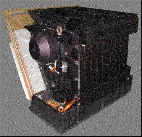
Severyanin OBRC (Onboard Radar Complex)
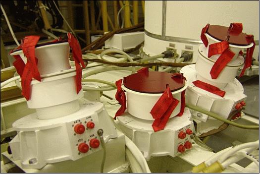
The small size radar Severyanin-M (translation from Russian - "Northerner") is a part of the on-board hardware of the spacecraft Meteor-M series designed and developed by the Research Institute of Precise Instruments, Moscow, Russia. Serveryanin-M is an X-band side-looking radar instrument providing vertical polarization. The main objective is sea ice monitoring in the polar regions, but the radar imagery can also be used for land surface observation, for vegetation monitoring, and a number of other applications. The system consists of two main components: the antenna subsystem and the electric unit. The radar antenna consists of seven segments, six of which are deployed after launch with the central segment attached to the zenith-pointing deck of the satellite. The instrument has a mass of 150 kg and requires 1 kW of power when in operation, the source data rate is 10 kbit/s. 13)
The OBRC instrument operates at a center frequency of 9.623 GHz and an incidence angle range of 25 -48º. A 450 to 600 km ground swath is covered by the radar, depending on the observation mode as it can operate in low and medium resolution mode. In low resolution mode, the radar reaches a ground resolution of 700-1,000 m while the medium resolution mode leads to images with a spatial resolution of 400-500 m.
Parameter | Value |
Center frequency (X-band, 3.1 cm wavelength) | 9.623 GHz |
Incidence angle access range | 25-48º |
Swath width | 450-600 km |
Spatial resolution in medium resolution mode | 400-500 m |
Spatial resolution in low resolution mode | 700-1000 m |
Source data rate | 10 Mbit/s |
The radar uses an uncontrolled antenna array, klystron transmitter, digital receiver and special digital device for forming the sounding signals, the echoed signals prefiltering and matching to the radiolink. It has embedded facilities for inner amplitude calibration. In addition there is possibility to change parameters of the sounding signal and some other radar parameters through the command radio-link from the Earth.
The spacecraft specifics dictated restrictions on the following radar characteristics:
- radar power consumption: not more than 1 kW
- radar mass: not more than 150 kg (including the antenna mass – not more 40 kg)
- data transfer rate of the radio-link used: not more than 10 kbit/s.
KMSS (Multispectral Scanning Imaging System)
KMSS was designed and developed at IKI (Space Research Institute), Moscow. The objective is Earth surface monitoring. The instrument comprises three pushbroom cameras in the VNIR range; two cameras (MSU-100) have a focal length of 100 mm; the third one (MSU-50), has a focal length of 50 mm. The two MSU-100 cameras are tilted ±14º in cross-track to each side of nadir; together they cover a swath width of 960 km, which is close to the swath of MSU-50. 14)
Each camera has a focal plane with 3 CCD lines (each covered with a corresponding filter) behind a common lens. The three-line camera system (with 3 CCD-lines in a focal plane and 1 lens, the corresponding detector elements of different bands look necessarily in different along-track directions) provides the following along-track observation directions: ±17º and 0º (nadir) for MSU-50, and ±8.7º and 0º for MSU-100. The KMSS instrument represents simply the mounting fixture of three separate cameras, and the KMSS image will be an image of 3 separate cameras put together in ground processing.
Parameter | Value |
Swath width (2 MSU-100, 1 MSU-50) | 960 km (cumulative of 2 cameras), 940 km |
FOV (Field of View) in cross-track direction | 31º, 62º |
Spatial resolution | 60 m (MSU-100) |
Total No of spectral bands | 6 |
Spectral bands (µm) of MSU-100 | 0.535-0.575; 0.630-0.680; 0,760-,900; |
No of CCD elements in cross-track | 8000 |
Data quantization | 8 bit |
SNR for bright objects (clouds at high sun elevation) | 200 |
Source data rate per band | 9.8 Mbit/s |
Source data rate of 1 camera system, 2 camera system | ~30 Mbit/s, ~60 Mbit/s |
MSU-100 mass, power | 2.9 kg, 6.8 W (peak power consumption) |
MSU-100 size | 210 x 200 x 200 mm (the last size - along the optical axis) |
MSU-50 size | 210 x 200 x 140 mm (the last size - along the optical axis) |
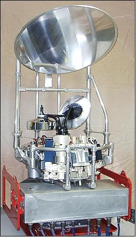
MTVZA-GY (Microwave Imaging/Sounding Radiometer)
MTVZA-GY was designed and developed at the Space Observations Center, Moscow, under contract to Roskosmos. The instrument is of MTVZA heritage flown on the Meteor-3M-1 mission (launch Dec. 10, 2001). MTVZA-GY is a passive 29-channel microwave radiometer - similar to the SSMIS (Special Sensor Microwave Imager Sounder) of the DMSP-F16 mission, as well as to NOAA's AMSU-A (Advanced Microwave Sounding Unit-A) and -B radiometers. Note: MTVZA-GY was named in memory of Gennady Ya Gus'kov (1919-2002, Moscow) - the Russian designer of various spaceborne instruments.
The objective of the MTVZA-GY instrument is to monitor ocean and land surfaces as well as global atmospheric parameters such as temperature and water vapor profiles and to obtain sea surface wind profiles. MTVZA-GY is a conical scanning instrument with a common field of view for imaging and sounding channels (simultaneous multispectral and polarization measurements), due to the single antenna design.
The operating frequencies are located in the transparent atmospheric windows at 10.6, 18.7, 23.8, 31.5, 36.7, 42, 48, and 91.65 GHz, as well as in the oxygen absorption lines at 52-57 GHz and water vapor at 183.31 GHz. 15) 16)
The instrument consists of a large rotating main reflector and an Instrument Support Structure facilitating the RF electronics and sensors as well as the spin mechanism and support systems. MTVZA-GY has a mass of 90 kg, requires 80 W of power and has a data rate of 35 kbit/s. The operating frequencies of the instrument cover the transparent atmospheric range, the oxygen absorption lines and the water vapor absorption range.
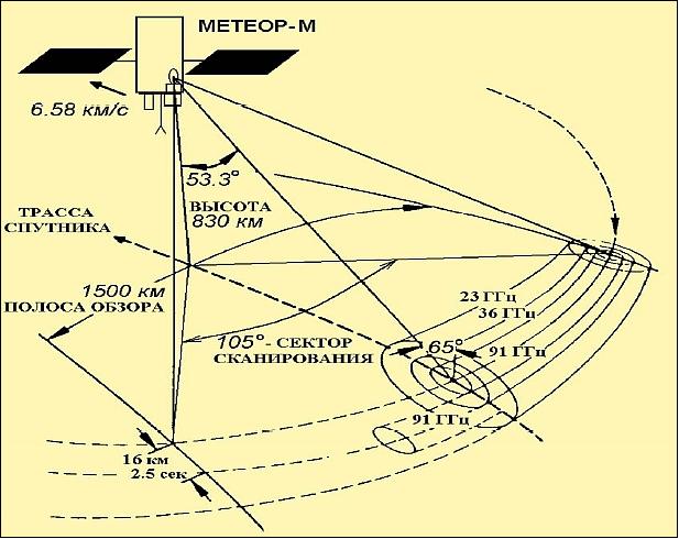
Observation geometry: MTVZA-GY is a conical-scanning radiometer rotating continuously about an axis parallel to the local spacecraft vertical with a period of 2.5 s. The view direction of the instrument is backwards (anti-velocity direction) with a viewing angle of 53.3º and an incidence angle of 65º (with respect the the surface). The scan direction is from the left to the right when looking in the aft direction of the spacecraft, with the active scene measurements in the range from -90º to +15º about the aft direction, resulting in a swath width of 1500 km.
Observation region | Parameter | Range of measurements | Error |
Ocean | SST Ice: age (gradations) |
| ±1.0 K |
Atmosphere | Temperature profile | up to 45 km | ±1.5 K |
Clouds: |
|
| |
Rain rate | 0-25 mm/h | ±5.0 mm/h | |
Land | Thickness of dry snow | up to 1.5 m | ±0.2 m |
Channel No | Center Frequency (GHz) | No of Passbands | Bandwidth (MHz) | Effective FOV | Pixel size (km x km) | Sensitivity (K/pixel) | Approx. peak sensitivity altitude (km) |
1 | 10.6 | 1 | 100 | 89 x 198 | 32 x 32 | 0.5 | - |
2 | 18.7 | 1 | 200 | 52 x 16 | 32 x 32 | 0.4 | - |
3 | 23.8 | 1 | 400 | 42 x 94 | 32 x 32 | 0.3 | - |
4 | 31.5 | 1 | 1000 | 35 x 76 | 32 x 32 | 0.3 | - |
5 | 36.5 | 1 | 1000 | 30 x 67 | 32 x 32 | 0.3 | - |
6 | 42 | 1 | 1000 | 26 x 60 | 32 x32 | 0.4 | - |
7 | 48 | 1 | 1000 | 24 x 43 | 32 x 32 | 0.4 | - |
8 | 52.80 | 1 | 400 | 21 x 48 | 48 x 48 | 0.4 | 2 |
9 | 53.30 | 1 | 400 | 21 x48 | 48 x 48 | 0.4 | 4 |
10 | 53.80 | 1 | 400 | 21 x 48 | 48 x 48 | 0.4 | 6 |
11 | 54.64 | 1 | 400 | 21 x 48 | 48 x 48 | 0.4 | 10 |
12 | 55.63 | 1 | 400 | 21 x 48 | 48 x 48 | 0.4 | 14 |
13 | 57.290344±0.3222±0.1 | 4 | 50 | 21 x 48 | 48 x 48 | 0.4 | 20 |
14 | 57.290344±0.3222±0.05 | 4 | 20 | 21 x 48 | 48 x 48 | 0.7 | 25 |
15 | 57.290344±0.3222±0.025 | 4 | 10 | 21 x 48 | 48 x 48 | 0.9 | 29 |
16 | 57.290344±0.3222±0.01 | 4 | 5 | 21 x 48 | 48 x 48 | 1.3 | 35 |
17 | 57.290344±0.3222±0.005 | 4 | 3 | 21 x 48 | 48 x 48 | 1.7 | 42 |
18 | 91.65 | 2 | 2000 | 14 x 30 | 16 x 16 | 0.6 | Surface |
19 | 183.31±7.0 | 2 | 1500 | 9 x 21 | 32 x 32 | 0.5 | 1.5 |
20 | 183.31±3.0 | 2 | 1000 | 9 x 21 | 32 x 32 | 0.6 | 2.9 |
21 | 183.31±1.0 | 2 | 500 | 9 x 21 | 32 x 32 | 0.8 | 5.3 |
All instrument channels are switched to four feed-horn antennas. MTVZA-GY employs a total-power radiometer design providing a better sensitivity (factor 2) over a conventional Dicke-switched system. The channels in the 10-48 GHz domain are direct amplification radiometers, while the channels in the 52-57, 91 and 183 GHz range are realized as as superheterodyne receivers using balanced mixers. The performance parameters are given in Tables 6 and 7. The following comment applies to Table 7:
• Channels 1-7 and 18 operate on both vertical and horizontal polarization
• Channels 13-17 operate on horizontal polarization only. - Hence, the total number of MTVZA-GY channels amounts to 29.
The antenna system of MTVZA-GY consists of an offset parabolic reflector of dimension 65 cm, illuminated by the four broadband feed-horn antennas. The antenna and radiometers are mounted on a drum for the purpose to provide an invariant viewing and polarization geometry for the reflector scan. The drum contains the various system components like digital data subsystem, power and the signal transfer assembly, which rotates continuously about an axis parallel to the local spacecraft vertical. The power, commands, all data, timing and telemetry signals pass through slip ring connectors to the rotating assembly.
Hot and cold reference absorbers are used for calibration. They are mounted on the non-rotating part of the instrument and are positioned such that they pass between the feed-horns and the parabolic reflector, occulting the feed-horns once on each scan. The temperature difference between the hot and cold target is expected to be 50-60 K.
Spatial resolution (km) | 16-198 (horizonal); 1.5 - 7 (vertical) | ||||||||
Conical scanning period | 2.55 s | ||||||||
Viewing angle | 53.3º | ||||||||
Incident angle | 65º | ||||||||
Swath width | 1500 km | ||||||||
Instrument mass, power | 90 kg, 80 W | ||||||||
Data rate, data quantization | 35 kbit/s; 16 bit | ||||||||
GGAK-M (Geophysical Monitoring System Komplex)
The geophysical Monitoring Complex consists of two instruments: 1) MSGI-MKA (Spectrometer for Geoactive Measurements), and 2) KGI-4C (Radiation Monitoring System).
The MSGI-MKA instrument features four channels for the measurement of the following parameters:
• Electron fluxes in the energy range of 0.1-15 keV (high-sensitivity channel)
• Ion (proton) fluxes in the energy range of 0.1-15 keV (high-sensitivity channel)
• Electron fluxes in the energy range of 0.1-15 keV (low-sensitivity channel)
• Monitoring of integral electron fluxes with a threshold energy of 40 keV
The FOV (Field of View) is 10º x 10º for each channel (3) and 20º x 20º for the integral electron flux. The instrument has a mass of 5 kg and a power consumption of 6.8 W.
KGI-4C (Radiation Monitoring System). The objective is to monitor flux densities within the following threshold energy ranges:
• Total proton flux threshold energy of: 5, 15, 25, 30, and 40 MeV
• Total electron flux threshold energy of: 0.17, 0.7, 1.7, 2.0 and 3.2 MeV
• Proton fluxes with threshold energies of: 25 and 90 MeV
The KGI-4C instrument has a mass of 12 kg and a power consumption of 6.8 W (max).
DCS (Data Collection System)
The objective is to collect in-situ data from DCPs (Data Collection Platforms) in the ground segment with location capability.
No description available.
Ground Segment
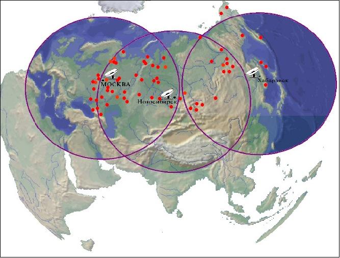
SRC (Space Research Center) "Planeta" of Moscow is the key organization of the CGS, (Core Ground Segment) that carries out all the main functions of the Meteor-M-1 mission - control, acquisition, processing, archiving, and dissemination of data, provided by Russian and foreign satellite systems.
• 3 Main centers:Europe (Moscow-Obninsk-Dolgoprudny)
• Siberia (Novosibirsk)
• Far-East (Khabarovsk)
In addition, there are 68 local centers.
References
1) Y. V. Trifonov, A. V. Gorbunov, V. F. Kharitonov, “S/C “Meteor-M” - a new stage of the operating meteorological space system,” Proceedings of the 31st International Symposium on Remote Sensing of Environment, Saint Petersburg, Russia, June 20-24, 2005
2) A. B. Uspensky, “Status of current and future Roshydrometsatellite programmes,” ITSC-16 (16th International TOVS Study Conference), Angra dos Reis, Brazil, May 07 –13, 2008, URL: http://cimss.ssec.wisc.edu/itwg/itsc/itsc16/presentations/11_06_uspensky.pdf
3) V. V. Asmus, V. N. Dyaduchenko, O. E. Milekhin, A. B. Uspensky, “Remote Sensing Products and Applications: Roshydromet Program,” EUMETSAT Meteorological Satellite Conference, Dubrovnik, Croatia, Sept. 19-23, 2005, URL: http://www.eumetsat.int/groups/cps/documents/document/pdf_conf_p46-s1_03_asmus_v.pdf
4) http://planet.iitp.ru/english/index_eng.htm
5) http://planet.iitp.ru/english/index_eng.htm
6) http://orbiter-forum.com/showthread.php?p=120297#post120297
7) http://www.russianspaceweb.com/meteor.html
8) “Report on the status of current and future Russian satellite systems,” CGMS (Coordination Group for Meteorological Satellites)-42 ROSH/ROSCWP-01, 25 April 2014, URL: http://www.eumetsat.int/website/wcm/idc/idcplg?IdcService=GET_FILE&RevisionSelectionMethod=Latest-Released&Rendition=Web&dDocName=CWPT_1210
9) http://planet.iitp.ru/english/index_eng.htm
10) Information provided by Boris Zhukov of IKI, Moscow
11) Research Center for Earth Operative Monitoring (NTs OMZ). URL: [web source no longer available]
12) Research Center for Earth Operative Monitoring (NTs OMZ). URL: [web source no longer available]
13) Sergey Vnotchenko, Michail Dostovalov, Vladimir Dudukin, Alexander Kovalenko, Tomas Musinyants, Viktor Riman, Aleksey Selyanin, Stanislav Smirnov, Andrey Telichev, Valentin Chernishov, Anatoliy Shishanov, “Wide-Swath Spaceborne SAR System "Severyanin-M" For Remote Sensing: First Results,” Proceedings of EUSAR 2012 (9th European Conference on Synthetic Aperture Radar), Nuremberg, Germany, April 23-26, 2012
14) Information provided by Boris Zhukov of IKI, Moscow
15) I. V. Cherny, G. M. Chernyavsky, N. N. Gorobets, “Spaceborne Microwave Image/Sounder MTVZA,” Proceedings of 25th ESA Antenna Workshop on Satellite Antenna Technology, ESTEC, Noordwijk, The Netherlands, Sept. 18-20, 2002, pp. 523-527
16) I. V. Cherny, G. M. Chernyavsky, “Microwave Imager/Sounder MTVZA of Space Meteor-3M,” Proceedings of 7th International Conference on Remote Sensing for Marine and Coastal Environments, Miami, FLA, May 20-22, 2002
Overview Spacecraft Launch Mission Status Sensor Complement Ground Segment References Back to top