Meteor-M2-2
EO
Atmosphere
Ocean
Cloud type, amount and cloud top temperature
Quick facts
Overview
| Mission type | EO |
| Agency | ROSKOSMOS, ROSHYDROMET |
| Mission status | Operational (nominal) |
| Launch date | 05 Jul 2019 |
| Measurement domain | Atmosphere, Ocean, Land, Gravity and Magnetic Fields, Snow & Ice |
| Measurement category | Cloud type, amount and cloud top temperature, Liquid water and precipitation rate, Atmospheric Temperature Fields, Cloud particle properties and profile, Aerosols, Multi-purpose imagery (ocean), Radiation budget, Multi-purpose imagery (land), Surface temperature (land), Vegetation, Albedo and reflectance, Gravity, Magnetic and Geodynamic measurements, Surface temperature (ocean), Atmospheric Humidity Fields, Ozone, Trace gases (excluding ozone), Sea ice cover, edge and thickness, Snow cover, edge and depth, Ocean surface winds |
| Measurement detailed | Cloud top height, Ocean imagery and water leaving spectral radiance, Cloud cover, Precipitation intensity at the surface (liquid or solid), Aerosol optical depth (column/profile), Cloud type, Cloud imagery, Aerosol Extinction / Backscatter (column/profile), Cloud liquid water (column/profile), Land surface imagery, Upward long-wave irradiance at TOA, Aerosol effective radius (column/profile), Fire fractional cover, Earth surface albedo, Magnetic field (scalar), Magnetic field (vector), Short-wave Earth surface bi-directional reflectance, Atmospheric specific humidity (column/profile), O3 Mole Fraction, Atmospheric temperature (column/profile), Land surface temperature, Sea surface temperature, CH4 Mole Fraction, Sea-ice cover, Snow cover, Wind speed over sea surface (horizontal), Normalized Differential Vegetation Index (NDVI), Sea-ice thickness, Height of tropopause |
| Instruments | DCS, KMSS, IKFS-2, MTVZA-GY, MSU-MR, GGAK-M |
| Instrument type | Imaging multi-spectral radiometers (vis/IR), Space environment, Imaging multi-spectral radiometers (passive microwave), Data collection, Atmospheric temperature and humidity sounders |
| CEOS EO Handbook | See Meteor-M2-2 summary |
Meteor-M2-2 Meteorological Mission
Launch Sensor Complement References
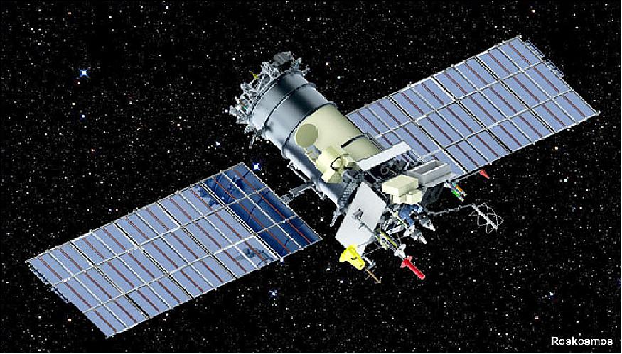
Like its two predecessors, the 2,750 kg Meteor-M2-2 satellite is designed to observe the global weather, the ozone layer, the ocean surface temperature and ice conditions to facilitate shipping in the polar regions of our planet. 1) 2)
The spacecraft was built at Moscow-based VNIIEM Corporation, which relied on its standard Resurs-UKP-M platform as a basis for the Meteor-M series.
Despite the promise from VNIIEM in 2017 to equip the Meteor M2-2 variant with the Severyanin radar for obtaining all-weather images of the Earth's surface, there was no sign that such a payload was installed onboard.
The Meteor-M2-2 was certified to work for at least five years. It will become the third spacecraft in the Meteor-3M network, after the Meteor-M No. 1 satellite, which was launched on Sept. 17, 2009, and Meteor-M No. 2 launched on July 8, 2014.
According to the original plan, the launch of the Meteor-M2-1 satellite would allow Russia to have three low-orbital meteorological satellites simultaneously in orbit, allowing a total meteorological coverage of the Russian territory from polar orbit every two or three days. However the original Meteor-M satellite lost most of its capabilities in 2014, or three years before Meteor M2-1 reached the launch pad and then itself was lost during ascent to orbit.
Development Status
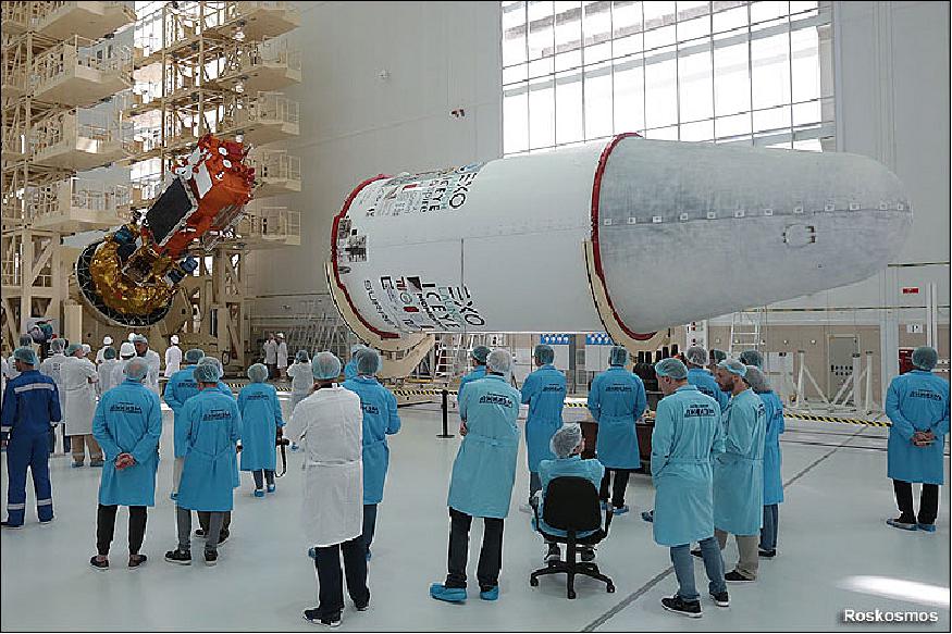
• On 27 June 2019, the fully assembled payload section was covered with its payload faring inside the spacecraft processing building. Its transportation to the vehicle assembly building via a trans-border gallery was performed on June 28 and on the same day, the payload section was integrated with the third stage of the launch vehicle. Roskosmos also announced the formation of a joint launch team from the Vostochny KTs branch of the TsENKI launch processing center and the Roskosmos State Corporation to support pad operations in the upcoming launch (Ref. 1).
• On 1 July , the upper composite, including the payload section and the third stage of the launch vehicle, was lifted from its assembly cradle and placed on the transporter/erector, where it was integrated with the booster stages of the Soyuz-2-1b rocket. The rollout of the fully assembled vehicle to the launch pad took place on the morning of July 2, 2019, between 03:00 and 04:15 Moscow Time and, after its installation in vertical position on the pad, the rocket was enclosed inside the MBO (Mobile Service Tower).
Launch
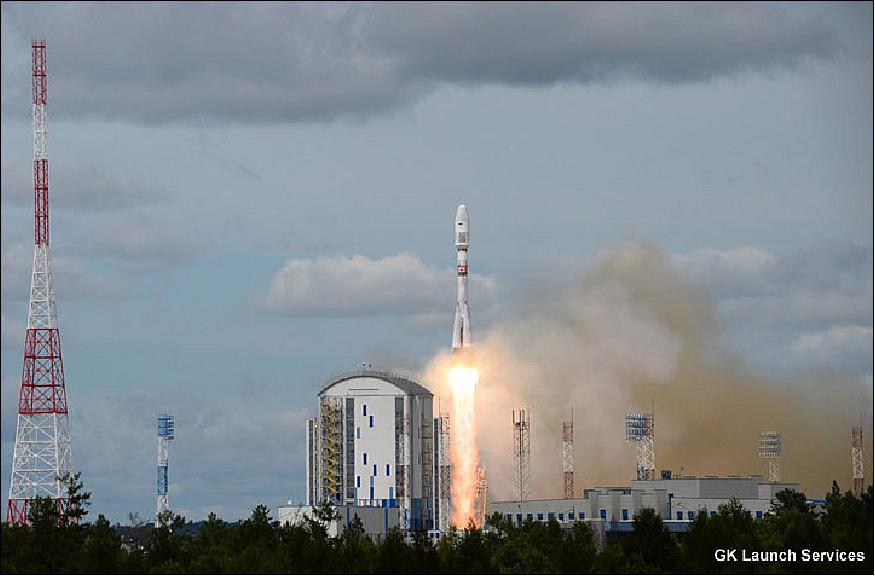
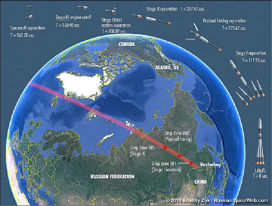
The Meteor M2-2 weather and climate-monitoring satellite (primary payload) was launched on 5 July 2019 (05:41:46 UTC) on a Soyuz-2-1b/Fregat rocket from Russia's far-eastern spaceport Vostochny. Spacecraft liftoff mass: ~2900 kg, payload mass: ~1250 kg (Ref. 1).
Heading north from Vostochny, the Soyuz-2.1b rocket gave the 33 satellites a ride to space in the first 10 minutes of the mission, then deployed a Fregat upper stage to conduct a series in burns to inject the payloads into three distinct near-polar orbits at different altitudes. 3)
Around five hours later, an update by Roscosmos — the Russian space agency — confirmed all 33 of the satellites separated from the Fregat upper stage, and officials declared the mission a success.
Orbit of the primary payload: Sun-synchronous orbit, altitude = 832 km, inclination = 98.6º.
After separation of the Meteor M2-2 weather satellite, the Fregat upper stage fired several more times to lower its orbit. Another batch of payloads separated in a targeted 580 km orbit with an inclination of 97.7º, followed a final deployment sequence in a targeted 530 km orbit inclined 97.5º to the equator, according to Roscosmos.
Nr. | Spacecraft | Mission | Developer / Operator |
1 | Meteor-M2-2 (primary mission) | Remote-sensing | VNIIEM / Roskosmos |
Secondary payloads | |||
2 | Momentus X1 (El Camino Real) | Microwave electro-thermal | Momentus Space (USA) |
3 | NSLSat-1 (6U CubeSat) | Antenna deployment experiment, | Clyde Space (UK) / NSLComm (Israel) |
4 | Lemur-2 (100) | Navigation, air/sea traffic control | SpireGlobal Inc., San Francisco, (USA) |
5 | Lemur-2 (101) | Navigation, air/sea traffic control | SpireGlobal Inc. (USA) |
6 | Lemur-2 (102) | Navigation, air/sea traffic control | SpireGlobal Inc. (USA) |
7 | Lemur-2 (103) | Navigation, air/sea traffic control | SpireGlobal Inc. (USA) |
8 | Lemur-2 (104) | Navigation, air/sea traffic control | SpireGlobal Inc. (USA) |
9 | Lemur-2 (105) | Navigation, air/sea traffic control | SpireGlobal Inc. (USA) |
10 | Lemur-2 (106) | Navigation, air/sea traffic control | SpireGlobal Inc. (USA) |
11 | Lemur-2 (107) | Navigation, air/sea traffic control | SpireGlobal Inc. (USA) |
12 | JAISAT-1 (3U CubeSat) | Ham radio | GOS (German Orbital Systems) GmbH / Thai ham radio society |
13 | EXOCONNECT | Experimental | GOS (German Orbital Systems) GmbH |
14 | D-Star One (Two 3U CubeSats) | Experimental | GOS (German Orbital Systems) GmbH |
15 | Lucky-7 (1U CubeSat) | Experimental 1U CubeSat | SkyFox Labs, (Czech Republic) |
16 | SEAM-2.0 (3U CubeSat) | Earth magnetic field measurements | Royal Technology Institute (Sweden) |
17 | MTCube (Robusta-1C, 1U CubeSat) | Space radiation monitoring | Montpellier University (France) |
18 | SONATE (3U CubeSat) | Experimental | University of Wuerzburg (Germany) |
19 | Beesat-9 (1U CubeSat) | Orbital navigation & UHF ISL communications | Technical University, Berlin (Germany) |
20 | Beesat-10 (1/4U CubeSat) | Orbital navigation & UHF ISL communications | Technical University, Berlin (Germany) |
21 | Beesat-11 (1/4U CubeSat) | Orbital navigation & UHF ISL communications | Technical University, Berlin (Germany) |
22 | Beesat-12 (1/4U CubeSat) | Orbital navigation & UHF ISL communications | Technical University, Berlin (Germany) |
23 | Beesat-13 (1/4U CubeSat) | Orbital navigation & UHF ISL communications | Technical University, Berlin (Germany) |
24 | MOVE-2b | Experimental | Technical University, Munich, Germany |
25 | TTU-100 (1U CubeSat) | X-band and optical communications | Technical University, Tallinn (Estonia) |
26 | Ecuador-UTE | Space weather, ionosphere research | Ecuador Technical University (Ecuador) |
27 | ICEYE-X4 | Radar (X-band) remote-sensing | ICEYE Oy (Finland) |
28 | ICEYE-X5 | Radar (X-band) remote-sensing | ICEYE Oy (Finland) |
29 | DoT-1 | Demonstration of Technology-1 | SSTL (UK) |
30 | MKA Sokrat | Space weather monitoring | Skobeltsin NIIYaF MGU (Russia) |
31 | VDNKhA-80 | Space weather monitoring | Skobeltsin NIIYaF MGU (Russia) |
32 | AmurSat (AmGU-1) | Space weather monitoring | Amur State University, AmGU (Russia) |
33 | CarboNIX | Technology demonstration payload to test a new | Exolaunch |
The launch of the Meteor M2-2 spacecraft comes a year-and-a-half after the last satellite in the Russian Meteor series, designated Meteor M2-1, was lost due to a programming error in the Soyuz rocket’s Fregat upper stage that prevented the mission from reaching orbit following a liftoff from Vostochny.
Sensor Complement
The Meteor M2-2 satellite, designed for a five-year mission, hosts four meteorological instruments: two multi-channel scanners and cameras to obtain infrared and visible images of clouds and ice cover, a microwave radiometer to measure temperature and humidity in the atmosphere, and an infrared spectrometer to monitor the ozone layer (Ref. 3).
In addition, the Meteor M2-2 satellite also carries a search-and-rescue radio transponder and a payload to relay data from remote weather stations and offshore buoys to Russian forecasters.
MSU-MR (Low-resolution Multispectral Scanner)
MSU-MR was designed and developed by FSUE/RISDE (Federal State Unitary Enterprise) / Russian Scientific Institute of Space Device Engineering), Moscow. Objective: Global and regional cloud cover mapping, SST (Sea Surface Temperature), and LST (Land Surface Temperature). The optomechanical MSU-MR instrument provides imagery in six bands in the VIS and IR spectral regions (similar in performance and function to the AVHRR/3 instrument on the POES missions of NOAA) with a spatial resolution of 1 km.
Parameter | Value |
Band No 1 (VIS= Visible) | 0.50 ± 0.2 - 0.70 ± 0.2 µm |
Band No 2 (VNIR=Visible Near Infrared) | 0.70 ± 0.2 - 1.10 ± 0.2 µm |
Band No 3 (SWIR= Short Wave Infrared) | 1.60 ±0.50 - 1.80 ± 0.50 µm |
Band No 4 (MWIR= Mid Wave Infrared) | 3.50 ± 0.50 - 4.10 ± 0.50 µm |
Band No 5 (TIR = Thermal Infrared) | 10.5 ± 0.50 - 11.5 ± 0.50 µm |
Band No 6 (TIR = Thermal Infrared) | 11.5 ± 0.50 - 12.5 ± 0.50 µm |
Scanning geometry-plane, scanning angle | 108º, 54º |
Swath width | 2800 km |
Angular resolution in all spectral channels | 1.2 +0.2 mrad |
Spatial resolution at nadir | 1 km |
SNR in bands 1 and 2, in band 3 | ≥ 200, ≥ 100 |
Overall relative measurement error of radiance in bands 1-3 | 10% |
Range of radiation temperature measured in bands 4-6 | 213-313 K |
NEDT (Noise Equivalent Differential Temperature) at 300 K |
|
Overall absolute measurement error at 333 K in bands 4-6 | 0.5 K |
Data quantization | 10 bit |
Calibration | Use of onboard calibration sources |
Data rate | 660 kbit/s |
Operational mode | Continuous |
Instrument mass | ≤ 70 kg |

KMSS (Multispectral Scanning Imaging System)
KMSS was designed and developed at IKI (Space Research Institute), Moscow. The objective is Earth surface monitoring. The instrument comprises three pushbroom cameras in the VNIR range; two cameras (MSU-100) have a focal length of 100 mm; the third one (MSU-50), has a focal length of 50 mm. The two MSU-100 cameras are tilted ±14º in cross-track to each side of nadir; together they cover a swath width of 960 km, which is close to the swath of MSU-50. 4)
Each camera has a focal plane with 3 CCD lines (each covered with a corresponding filter) behind a common lens. The three-line camera system (with 3 CCD-lines in a focal plane and 1 lens, the corresponding detector elements of different bands look necessarily in different along-track directions) provides the following along-track observation directions: ±17º and 0º (nadir) for MSU-50, and ±8.7º and 0º for MSU-100. The KMSS instrument represents simply the mounting fixture of three separate cameras, and the KMSS image will be an image of 3 separate cameras put together in ground processing.
Parameter | Value |
Swath width (2 MSU-100, 1 MSU-50) | 960 km (cumulative of 2 cameras), 940 km |
FOV (Field of View) in cross-track direction | 31º, 62º |
Spatial resolution | 60 m (MSU-100) |
Total No of spectral bands | 6 |
Spectral bands (µm) of MSU-100 | 0.535-0.575; 0.630-0.680; 0,760-,900; |
No of CCD elements in cross-track | 8000 |
Data quantization | 8 bit |
SNR for bright objects (clouds at high sun elevation) | 200 |
Source data rate per band | 9.8 Mbit/s |
Source data rate of 1 camera system, 2 camera system | ~30 Mbit/s, ~60 Mbit/s |
MSU-100 mass, power | 2.9 kg, 6.8 W (peak power consumption) |
MSU-100 size | 210 x 200 x 200 mm (the last size - along the optical axis) |
MSU-50 size | 210 x 200 x 140 mm (the last size - along the optical axis) |
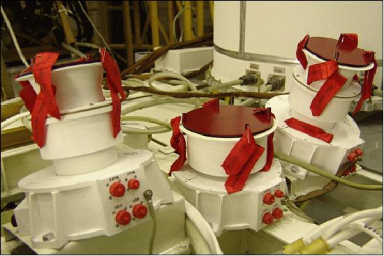
MTVZA-GY (Microwave Imaging/Sounding Microwave Radiometer)
MTVZA-GY was designed and developed at the Space Observations Center, Moscow, under contract to Roskosmos. The instrument is of MTVZA heritage flown on the Meteor-3M-1 mission (launch Dec. 10, 2001). MTVZA-GY is a passive 29-channel microwave radiometer - similar to the SSMIS (Special Sensor Microwave Imager Sounder) of the DMSP-F16 mission, as well as to NOAA's AMSU-A (Advanced Microwave Sounding Unit-A) and -B radiometers. Note: MTVZA-GY was named in memory of Gennady Ya Gus'kov (1919-2002, Moscow) - the Russian designer of various spaceborne instruments.
The objective of the MTVZA-GY instrument is to monitor ocean and land surfaces as well as global atmospheric parameters such as temperature and water vapor profiles and to obtain sea surface wind profiles. MTVZA-GY is a conical scanning instrument with a common field of view for imaging and sounding channels (simultaneous multispectral and polarization measurements), due to the single antenna design.
The operating frequencies are located in the transparent atmospheric windows at 10.6, 18.7, 23.8, 31.5, 36.7, 42, 48, and 91.65 GHz, as well as in the oxygen absorption lines at 52-57 GHz and water vapor at 183.31 GHz. 5) 6)
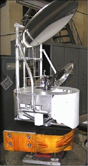
The instrument consists of a large rotating main reflector and an Instrument Support Structure facilitating the RF electronics and sensors as well as the spin mechanism and support systems. MTVZA-GY has a mass of 90 kg, requires 80 W of power and has a data rate of 35 kbit/s. The operating frequencies of the instrument cover the transparent atmospheric range, the oxygen absorption lines and the water vapor absorption range.
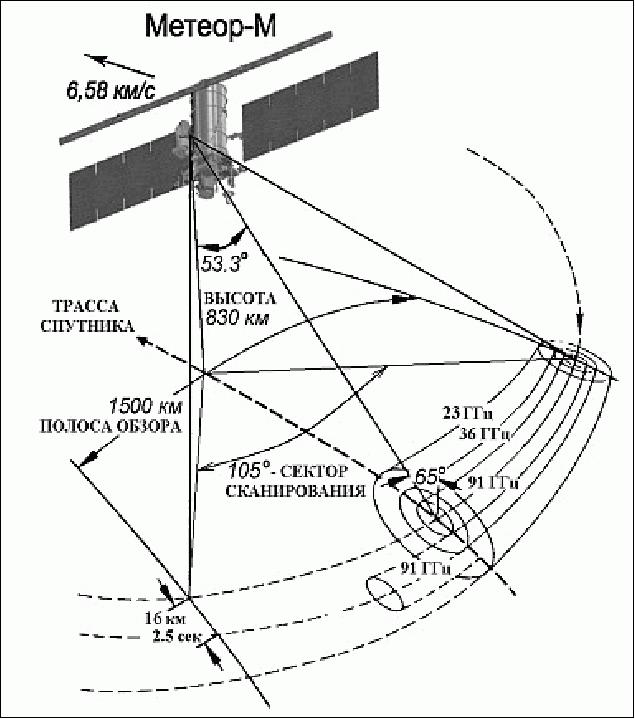
Observation geometry: MTVZA-GY is a conical-scanning radiometer rotating continuously about an axis parallel to the local spacecraft vertical with a period of 2.5 s (24 rpm). The view direction of the instrument is backwards (anti-velocity direction) with a viewing angle of 53.3º and an incidence angle of 65º (with respect the the surface). The scan direction is from the left to the right when looking in the aft direction of the spacecraft, with the active scene measurements in the range from -90º to +15º about the aft direction, resulting in a swath width of 1500 km.
Observation region | Parameter | Range of measurements | Error |
Ocean | SST Ice: age (gradations) |
| ±1.0 K |
Atmosphere | Temperature profile | up to 45 km | ±1.5 K |
Clouds: |
|
| |
Rain rate | 0-25 mm/h | ±5.0 mm/h | |
Land | Thickness of dry snow | up to 1.5 m | ±0.2 m |
Channel No | Center Frequency (GHz) | No of Passbands | Bandwidth (MHz) | Effective FOV | Pixel size (km x km) | Sensitivity (K/pixel) | Approx. peak sensitivity altitude (km) |
1 | 10.6 | 1 | 100 | 89 x 198 | 32 x 32 | 0.5 | - |
2 | 18.7 | 1 | 200 | 52 x 16 | 32 x 32 | 0.4 | - |
3 | 23.8 | 1 | 400 | 42 x 94 | 32 x 32 | 0.3 | - |
4 | 31.5 | 1 | 1000 | 35 x 76 | 32 x 32 | 0.3 | - |
5 | 36.5 | 1 | 1000 | 30 x 67 | 32 x 32 | 0.3 | - |
6 | 42 | 1 | 1000 | 26 x 60 | 32 x32 | 0.4 | - |
7 | 48 | 1 | 1000 | 24 x 43 | 32 x 32 | 0.4 | - |
8 | 52.80 | 1 | 400 | 21 x 48 | 48 x 48 | 0.4 | 2 |
9 | 53.30 | 1 | 400 | 21 x48 | 48 x 48 | 0.4 | 4 |
10 | 53.80 | 1 | 400 | 21 x 48 | 48 x 48 | 0.4 | 6 |
11 | 54.64 | 1 | 400 | 21 x 48 | 48 x 48 | 0.4 | 10 |
12 | 55.63 | 1 | 400 | 21 x 48 | 48 x 48 | 0.4 | 14 |
13 | 57.290344±0.3222±0.1 | 4 | 50 | 21 x 48 | 48 x 48 | 0.4 | 20 |
14 | 57.290344±0.3222±0.05 | 4 | 20 | 21 x 48 | 48 x 48 | 0.7 | 25 |
15 | 57.290344±0.3222±0.025 | 4 | 10 | 21 x 48 | 48 x 48 | 0.9 | 29 |
16 | 57.290344±0.3222±0.01 | 4 | 5 | 21 x 48 | 48 x 48 | 1.3 | 35 |
17 | 57.290344±0.3222±0.005 | 4 | 3 | 21 x 48 | 48 x 48 | 1.7 | 42 |
18 | 91.65 | 2 | 2000 | 14 x 30 | 16 x 16 | 0.6 | Surface |
19 | 183.31±7.0 | 2 | 1500 | 9 x 21 | 32 x 32 | 0.5 | 1.5 |
20 | 183.31±3.0 | 2 | 1000 | 9 x 21 | 32 x 32 | 0.6 | 2.9 |
21 | 183.31±1.0 | 2 | 500 | 9 x 21 | 32 x 32 | 0.8 | 5.3 |
All instrument channels are switched to four feed-horn antennas. MTVZA-GY employs a total-power radiometer design providing a better sensitivity (factor 2) over a conventional Dicke-switched system. The channels in the 10-48 GHz domain are direct amplification radiometers, while the channels in the 52-57, 91 and 183 GHz range are realized as as superheterodyne receivers using balanced mixers. The performance parameters are given in Tables 5 and 6. The following comment applies to Table 7:
• Channels 1-7 and 18 operate on both vertical and horizontal polarization
• Channels 13-17 operate on horizontal polarization only. - Hence, the total number of MTVZA-GY channels amounts to 29.
The antenna system of MTVZA-GY consists of an offset parabolic reflector of dimension 65 cm, illuminated by the four broadband feed-horn antennas. The antenna and radiometers are mounted on a drum for the purpose to provide an invariant viewing and polarization geometry for the reflector scan. The drum contains the various system components like digital data subsystem, power and the signal transfer assembly, which rotates continuously about an axis parallel to the local spacecraft vertical. The power, commands, all data, timing and telemetry signals pass through slip ring connectors to the rotating assembly.
Instrument calibration: Hot and cold reference absorbers are used for calibration. They are mounted on the non-rotating part of the instrument and are positioned such that they pass between the feed-horns and the parabolic reflector, occulting the feed-horns once on each scan. The temperature difference between the hot and cold target is expected to be 50-60 K.
Spatial resolution (km) | 16-198 (horizontal); 1.5 - 7 (vertical) | ||||||||
Conical scanning period | 2.55 s | ||||||||
Viewing angle | 53.3º | ||||||||
Incident angle | 65º | ||||||||
Swath width | 1500 km | ||||||||
Instrument mass, power | 90 kg, 80 W | ||||||||
Data rate, data quantization | 35 kbit/s; 16 bit | ||||||||
GGAK-M (Geophysical Monitoring System Komplex)
The geophysical Monitoring Complex is dedicated to the measurement of geophysical properties consisting of two instruments:
1) MSGI-MKA (Spectrometer for Geoactive Measurements), an electrostatic analyzer
2) KGI-4C (Radiation Monitoring System).
The MSGI-MKA instrument can detect electrons in the energy range of 0.1 to 15 keV, protons at 0.1 to 15 keV in a high- and low-sensitivity channel. Integral electron fluxes can be measured up to 40 keV. The instrument features four channels for the measurement of the following parameters:
• Electron fluxes in the energy range of 0.1-15 keV (high-sensitivity channel)
• Ion (proton) fluxes in the energy range of 0.1-15 keV (high-sensitivity channel)
• Electron fluxes in the energy range of 0.1-15 keV (low-sensitivity channel)
• Monitoring of integral electron fluxes with a threshold energy of 40 keV
The FOV (Field of View) is 10º x 10º for each channel (3) and 20º x 20º for the integral electron flux. The instrument has a mass of 5 kg and a power consumption of 6.8 W.
KGI-4C (Radiation Monitoring System). The objective is to monitor flux densities within the following threshold energy ranges:
• Total proton flux threshold energy of: 5, 15, 25, 30, and 40 MeV
• Total electron flux threshold energy of: 0.17, 0.7, 1.7, 2.0 and 3.2 MeV
• Proton fluxes with threshold energies of: 25 and 90 MeV
The KGI-4C instrument has a mass of 12 kg and a power consumption of 6.8 W (max).
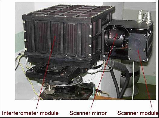
IRFS-2 (Infrared Fourier Spectrometer-2)
The instrument is an advanced infrared sounder with the objective to provide atmospheric temperature and humidity profiles. Note: The Russian abbreviation for the instrument is simply “IKFS”.
The IRFS-2 instrument was designed and developed by the Keldysh Research Center. The instrument consists of an optical unit, a data processing and power supply unit and a radiative cooler that keeps the focal plane at an appropriate temperature to reduce the dark current of the detectors. The optical system is comprised of an interferometric module with a double pendulum interferometer and a radiometer, a pointing module and a calibration module. 7)
IRFS-2 covers a spectral range of 5 to 15 µm at a spectral resolution of 0.4 cm-1. The instrument covers a ground swath of 1,000 to 2,500 km with a spatial resolution of about 30 km. The radiometer operates at a radiometric accuracy of 0.5 K. The instrument covers the carbon dioxide absorption band to obtain temperature profiles, two atmospheric windows for cloud properties and surface parameters, the ozone absorption band for ozone sounding and the absorption bands of water, nitrous oxide and methane for moisture profiles and column amount measurement of these substances.
Parameter | Value |
Spectral range | 5.0-15 µm (2000-667 cm-1) |
Spectral resolution FWHM (Full Width Half Maximum) | 0.5 cm-1 |
Digitization interval | 0.25 s m-1 |
Detection limit [NESR (Noise-Equivalent Spectral Radiance)] |
|
Measurement error of object spectral brightness in terms of equivalent temperature at wavelength 11-12 µm and object temperature 280-300 K | 0.5 K |
IFOV (Instantaneous Field of View), corresponding to a spatial resolution at nadir | 40 mrad x 40 mrad, 30 km |
The measurements are made across the flight path with horizontal pitch depending on view width: | - 2500 km swath width, pitch = 100-110 km |
Periodicity of interferogram | ≤ 0.6 s |
Source data rate | ~600 kbit/s |
Instrument mass, power | ~50 kg, 50 W |
Band No | Spectral region | Absorption band | Application |
1 | 665 - 780 cm-1 | CO2 |
|
2 | 790 - 980 cm-1 | Atmospheric window | Surface parameters (Ts, εv) Cloud properties |
3 | 1000 - 1070 cm-1 | O3 | Ozone sounding |
4 | 1080 - 1150 cm-1 | Atmospheric window | Ts, εv (cloud properties) |
5 | 1210 - 1650 cm-1 | H2O, N2O, CH4 | Moisture profile, CH4, N2O column amounts |
DCS (Data Collection System)
The objective is to collect in-situ data from DCPs (Data Collection Platforms) in the ground segment with location capability.
No description available.
References
1) Anatoly Zak, ”Meteor-M2-2 satellite,” 5 July 2019, URL:
http://www.russianspaceweb.com/meteor-m2-2.html
2) William Graham, Soyuz-2-1B launches Meteor-M No.2-2 and numerous secondary payloads,” NASA Spaceflight.com, 4 July 2019, URL:
https://www.nasaspaceflight.com/2019/07/soyuz-2-1b-launch-meteor-m-no-2-2/
3) Stephen Clark, ”Soyuz rocket and Fregat upper stage deliver 33 satellites to three different orbits,” Spaceflight Now, 5 July 2019, URL: https://spaceflightnow.com/2019/07/05
/soyuz-rocket-and-fregat-upper-stage-deliver-33-satellites-to-three-different-orbits/
4) Information provided by Boris Zhukov of IKI, Moscow
5) I. V. Cherny, G. M. Chernyavsky, N. N. Gorobets, “Spaceborne Microwave Image/Sounder MTVZA,” Proceedings of 25th ESA Antenna Workshop on Satellite Antenna Technology, ESTEC, Noordwijk, The Netherlands, Sept. 18-20, 2002, pp. 523-527
6) I. V. Cherny, G. M. Chernyavsky, “Microwave Imager/Sounder MTVZA of Space Meteor-3M,” Proceedings of 7th International Conference on Remote Sensing for Marine and Coastal Environments, Miami, FLA, May 20-22, 2002
7) A. B. Uspensky, A.N. Rublev, Y. M. Timofeev, A. V. Polyakov, F. S. Zavelevich, Y. M. Golovin, D. A. Kozlov, “Atmospheric and surface parameters retrieved with IR-sounder IRFS-2 data – numerical modeling,” IASI Infrared Accuracy from Space In a fragile world, Hyères Les Palmiers, France, 4-8 February 2013, URL: http://smsc.cnes.fr/IASI/PDF/conf3/10_04-Uspensky_Alexander.pdf
The information compiled and edited in this article was provided by Herbert J. Kramer from his documentation of: ”Observation of the Earth and Its Environment: Survey of Missions and Sensors” (Springer Verlag) as well as many other sources after the publication of the 4th edition in 2002. - Comments and corrections to this article are always welcome for further updates (eoportal@symbios.space).