NPOESS (National Polar-Orbiting Operational Environmental Satellite System)
EO
Cancelled
Atmosphere
Ocean
Quick facts
Overview
| Mission type | EO |
| Agency | NOAA |
| Mission status | Cancelled |
| Measurement domain | Atmosphere, Ocean, Land, Gravity and Magnetic Fields, Snow & Ice |
| Measurement category | Cloud type, amount and cloud top temperature, Liquid water and precipitation rate, Atmospheric Temperature Fields, Cloud particle properties and profile, Ocean colour/biology, Aerosols, Multi-purpose imagery (ocean), Radiation budget, Multi-purpose imagery (land), Surface temperature (land), Vegetation, Albedo and reflectance, Gravity, Magnetic and Geodynamic measurements, Surface temperature (ocean), Atmospheric Humidity Fields, Ozone, Trace gases (excluding ozone), Sea ice cover, edge and thickness, Soil moisture, Snow cover, edge and depth, Ocean surface winds, Atmospheric Winds |
| Measurement detailed | Cloud top height, Precipitation Profile (liquid or solid), Atmospheric pressure (over sea surface), Ocean imagery and water leaving spectral radiance, Aerosol absorption optical depth (column/profile), Ocean chlorophyll concentration, Downward long-wave irradiance at Earth surface, Cloud cover, Cloud optical depth, Precipitation intensity at the surface (liquid or solid), Aerosol optical depth (column/profile), Cloud type, Cloud ice (column/profile), Cloud imagery, Cloud base height, Cloud liquid water (column/profile), Land surface imagery, Upward short-wave irradiance at TOA, Upward long-wave irradiance at TOA, Fire temperature, Vegetation type, Fire fractional cover, Earth surface albedo, Downwelling (Incoming) solar radiation at TOA, Magnetic field (scalar), Magnetic field (vector), Leaf Area Index (LAI), Land cover, Atmospheric specific humidity (column/profile), O3 Mole Fraction, Atmospheric temperature (column/profile), Land surface temperature, Sea surface temperature, Wind vector over sea surface (horizontal), Sea-ice cover, Snow cover, Soil moisture at the surface, Wind speed over sea surface (horizontal), Normalized Differential Vegetation Index (NDVI), CO2 Mole Fraction, Sea-ice type, Soil type, Total electron content (TEC), Downward short-wave irradiance at Earth surface, Sea-ice surface temperature, Long-wave Earth surface emissivity, Atmospheric pressure (over land surface), Upwelling (Outgoing) long-wave radiation at Earth surface, Wind vector over land surface (horizontal), Wind stress |
| Instruments | A-DCS4, CERES, S&R (NOAA), TSIS-1/SIM, OMPS, SESS, ATMS, CrIS, VIIRS, CMIS, SARSAT, SEM-N |
| Instrument type | Imaging multi-spectral radiometers (vis/IR), Earth radiation budget radiometers, Space environment, Magnetic field, Atmospheric chemistry, Communications, Imaging multi-spectral radiometers (passive microwave), Data collection, Atmospheric temperature and humidity sounders |
| CEOS EO Handbook | See NPOESS (National Polar-Orbiting Operational Environmental Satellite System) summary |
NPOESS (National Polar-Orbiting Operational Environmental Satellite System)
NPOESS is the next generation operational US polar-orbiting environmental satellite system under development, replacing the current generation POES and DMSP satellite constellations. The objective of the NPOESS program is to provide a single, national polar-orbiting remote-sensing capability for meteorological, oceanographic, climatic and space environmental data that will satisfy the operational demands of both the US civilian and military communities. 1)
The NPOESS program is built on international partnerships. NPOESS embraces international collaboration and cooperation in the development and operation of this important contributor to GEOSS (Global Earth Observation System of Systems). NPOESS is privileged to have strong partnerships across the globe. These partners include EUMETSAT (European Organization for the Exploitation of Meteorological Satellites), NSC (Norwegian Space Centre), ISRO (Indian Space Research Organization), and JAXA (Japanese Aerospace Exploration Agency). NPOESS data will be available world-wide.
Background
In the fall of 1993, the US National Performance Review (NPR) and the subsequent Presidential Decision Directive/NSTC-2 (May 5, 1994) called on DOC, DoD and NASA, to “converge” the US civil and military operational meteorological satellite programs (POES of NOAA and DMSP of DoD), in order to reduce duplication of effort and to generate cost savings. In October 1994, an Integrated Program Office (IPO), consisting of a team made up of NOAA, NASA and DoD representatives, was established organizationally under NOAA (with the IPO Headquarters located in Silver Spring, MD) with the explicit objective to integrate their separate meteorological programs into a single program that includes: planning, development, management, acquisition, and operations. A tri-agency MOA (Memorandum of Agreement) was signed in May 1995. The merged program received the name of NPOESS (National Polar-orbiting Operational Environmental Satellite System). The IPO is a tri-agency office reporting through NOAA to an Executive Committee of representatives from DOC, DoD and NASA. 2)
The IPO plan for NPOESS is to have the first satellite ready for launch in the 2011 time frame. As a consequence, the previously planned POES O, P, and Q series satellites have been cancelled, as well as the previously planned follow-on system to DMSP, known as the Block-6 series. In May 1998, the US Air Force Space Command transferred its day-to-day operations of the DMSP spacecraft to NOAA. With this action, NOAA assumed full responsibility for the operation of both the POES and DMSP satellite constellations. NOAA maintains and conducts joint satellite control operations at a collocated operations center where it also conducts operations of NOAA's GOES (Geostationary Operational Environmental Satellite) series (from Suitland, MD). 3)
NPOESS Transition Period Overview
The merging/evolution of the DMSP- and POES series has the following consequences:
• For the present and continuing into the latter part of the 1st decade of the 21st century, US polar-orbiting operational environmental/meteorological services will continue to be met by “flying-out” the remaining current generation satellites of each series (POES ATN and DMSP-5D3). This “fly-out” will be accomplished in a manner consistent with the current operation of these legacy programs (i.e. orbits, capabilities, etc. will remain unchanged).
• By 2005/6, the already planned merger of the civil US/European polar orbiting systems will consist of a total of two operational satellites (a US “afternoon” spacecraft with a European “mid-morning” spacecraft), a coordinated system, referred to as the IJPS (Initial Joint Polar System). As stated previously, one orbital plane (the traditional civil ”afternoon orbit”) will be provided/operated by NOAA (remaining POES series up to the NOAA-N' mission), the other orbital plane (the traditional civil “mid-morning” orbit, now maintained by NOAA spacecraft) will be provided by EUMETSAT with the start of the MetOp series (MetOp-1 launch in 2005). The Metop series satellites will be launched into a mid-morning orbit (with the following NOAA-provided instruments: AVHRR/3, HIRS/4, AMSU-A and SEM-2), while the POES series satellites will support the afternoon orbit.
• On the other hand, European-provided instruments are flown on NOAA-POES satellites since 1978, starting with the Argos DCS (Data Collection System) of CNES, and SSU (Stratospheric Sounding Unit), a UK sensor provided by BMO - on TIROS-N (launch Oct. 13, 1978) and subsequent NOAA satellites. The S&RSAT (Search & Rescue Satellite) payload, first flown on NOAA-8 (launch March 28, 1983), is provided by France and Canada. Three AMSU-B (Advanced Microwave Sounding Unit - B) instruments of UKMO are being flown on NOAA-K (NOAA-15, launch May 13, 1998), NOAA-L (NOAA-16, launch Sept. 21, 2000), and NOAA-M (NOAA-17, launch June 24, 2002) satellites. The MHS (Microwave Humidity Sounder), a EUMETSAT instrument, is planned to be flown on on the NOAA-N and N' satellites.
• For the NPOESS transition period, there are also operational polar orbiting satellites of the continuing DoD DMSP series (up to F-20), operated by NOAA that will continue to fly in their traditional orbital planes (early morning and mid-morning).
• The next-generation NPOESS series is planned to begin operations with an initial launch planned in the timeframe of 2014, and full operational capability being achieved around 2015. The overall polar orbiting environmental satellite constellation (beyond 2016) will consist of a total of two US satellites, namely the two NPOESS S/C provided and operated by the IPO, with continuing critical sounding data contributions to be provided by the mid-morning MetOp series S/C provided and operated by EUMETSAT. ARGOS Data Collection (DCS) and Search and Rescue (S&RSAT) systems will also continue to be flown as well.
• The NPOESS program is preceded by the launch of a single satellite in 2011, referred to as NPP (NPOESS Preparatory Project) to test the performance of several new NPOESS instruments and to provide climatic data continuity from the Earth Observing System (EOS) satellites (EOS/Terra and EOS/Aqua), operated by NASA.
• The DoD Coriolis mission with the WindSat instrument, implemented and managed by NRL, is a passive microwave technology demonstration mission and considered a further risk reduction project for NPOESS (validation of the CMIS instrument). A launch of Coriolis took place on January 6, 2003.
The NPOESS system is required to provide an operational remote-sensing capability to acquire and receive in real-time at field terminals global and regional environmental imagery and meteorological, climatic, terrestrial, oceanographic and solar-geophysical and other data in support of mission requirements. The NPOESS data sets, consisting of 55 EDRs (Environmental Data Records), will contain a number of variables that are currently not included in operational measurements (such as: radiation budget, total ozone, wind speed and direction, ocean topography, and ocean color) and will offer improved quality for some variables now being measured (such as: atmospheric moisture and temperature profiles, all-weather SST, and vegetation indices). 4)
The NPOESS Program Cancelled in 2010
In Feb. 2010, the NPOESS (National Polar-orbiting Environmental Satellite System) tri-agency program was terminated by the US government due to severe cost overruns and program delays (effective termination in April 2010). The NPOESS program was a joint DoD/NOAA/NASA endeavor that tried to integrate the capabilities and infrastructure of the NOAA POES (Polar-Orbiting Environmental Satellite) program, the DoD DMSP (Defense Meteorological Satellite Program), and NASA’s long-term continuous climate record collection. - The President's FY 2011 budget request for NOAA directed the NPOESS program to be split into separate NOAA/NASA and DoD programs.
The major challenge of NPOESS was jointly executing the program between three agencies of different size with divergent objectives and different acquisition procedures.
In 2009, an IRT (Independent Review Team) concluded that the current NPOESS program, in the absence of managerial and funding adjustments, has a low probability of success and data continuity is at extreme risk. The Office of Science and Technology, with the Office of Management and Budget and the National Security Council, as well as representatives from each agency, examined various options to increase the probability of success and reduce the risk to data continuity. 6) 7) 8) 9)
NOAA's newly restructured satellite program, the civilian JPSS (Joint Polar Satellite System), was created in the aftermath of the White House's Feb. 2010 decision to cancel NPOESS. The development of the new JPSS will be managed by NASA/GSFC while the spacecraft will be owned and operated by NOAA. The launch of JPSS-1 is planned for 2016.
NOAA, through NASA as its acquisition agent, will procure the afternoon orbit assets that support its civil weather and climate requirements and DoD will independently procure assets for the morning orbit military mission - referred to as DWSS (Defense Weather Satellite System). Both agencies will continue to share environmental measurements made by the system and support the operations of a shared common ground system.
The Administration decision for the restructured Joint Polar Satellite System will continue the development of critical Earth observing instruments required for improving weather forecasts, climate monitoring, and warning lead times of severe storms. NASA’s role in the restructured program will be modeled after the procurement structure of the successful POES (Polar Operational Environmental Satellite) and GOES (Geostationary Operational Environmental Satellite) programs, where NASA and NOAA have a long and effective partnership. The partner agencies are committed to maintaining collaborations towards the goal of continuity of earth observations from space.
The restructured JPSS (Joint Polar Satellite System) is planned to provide launch readiness capability in FY 2015 and FY 2018 (with launches of JPSS-1 in 2016 and JPSS-2 in 2019, respectively) in order to minimize any potential loss of continuity of data for the afternoon orbit in the event of an on orbit or launch failure of other components in the system. Final readiness dates will not be baselined until all transition activities are completed.
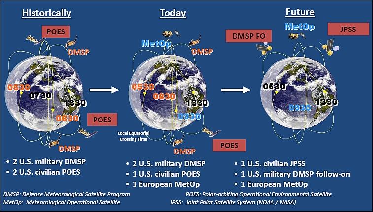
The following restructured concept scenario emerged in 2010: 10)
• NOAA/NASA Joint Polar Satellite System (JPSS) covers the afternoon (13:30 hours) orbit
• JPSS flies an “NPP-like” satellite bus
• DoD covers the early morning (05:30 hours) orbit. A DMSP Follow-on program (beyond DMSP-F-20) is in planning.
• NOAA manages the JPSS ground system.
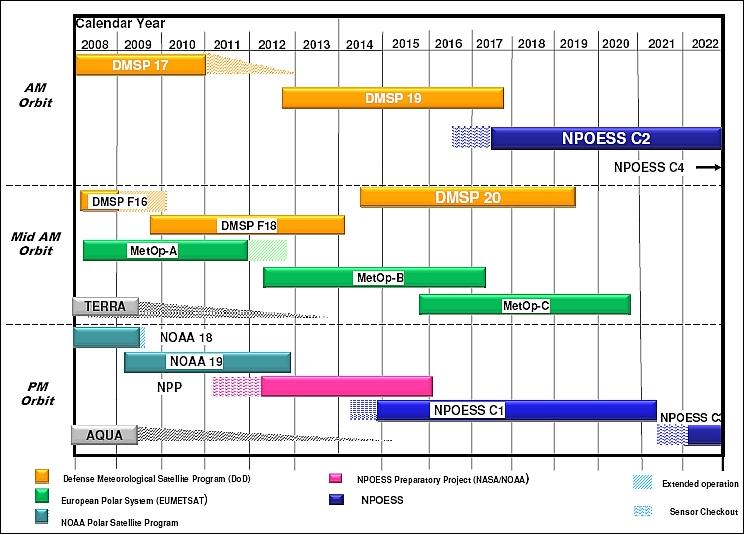
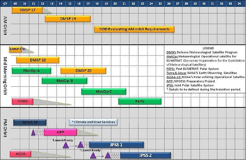
The European polar weather satellite program of EUMETSAT, namely the MetOp series, complements this new overall scenario through the EPS (EUMETSAT Polar System) agreements (Figure 4). The MetOp program provides observations in the mid-morning orbit (9.30 hours).
Current (2011) situation (Figure 4):
• The USAF (US Air Force) has two spacecraft left in storage (DMSP-19 and DMSP-20) to continue its observation program. DMSP-19 will be flown in the morning orbit, while DMSP-20 is considered for the afternoon orbit.
• NOAA launched its final POES series spacecraft (NOAA-19) in Feb. 2009.
• The launch of the NPP (NPOESS Preparatory Project) spacecraft is planned for late 2011 (afternoon orbit).
• The future JPSS spacecraft are allocated for the afternoon orbit.
• EUMETSAT is providing long-term coverage of the civilian polar weather program in the morning orbit.
NPOESS System Overview
NPOESS development procurement: IPO adopted a new procurement approach (agreed upon by all parties) and based upon a fully defined set of integrated operational requirements to meet the needs of the nation's civil and military users for environmental satellite data. This effort resulted in the definition of 55 EDRs (Environmental Data Records), encompassing the Earth science disciplines (e.g., atmospheric temperature and moisture profiles, precipitable water, vegetation index, sea surface temperature, ocean surface winds, aerosols, ozone, etc., as well as the required performance characteristics for each of these data). The full set of 55 EDRs will constitute the global SMD (Stored Mission Data) that will be available to users worldwide. Subsets of these data will also be broadcast from the NPOESS spacecraft in real-time at LRD (Low Rate Data) and HRD (High Rate Data) rates to field terminals worldwide. Performance characteristics for each of the 55 EDRs were defined and bounded between “threshold” values that represent minimally acceptable performance for an attribute and “objective” levels that represent performance that would have significant added value to users. - The new EDR strategy certainly deviates from traditional practice where the contractor was presented with a specification of the satellite and its payload. In the new approach, the design is left to the contractor.
In 2000, the IPO initiated a program definition and risk reduction phase to define the NPOESS total system architecture, including space, ground processing, and command, control, and communications components, as well as to develop specifications for sensor/spacecraft integration. - This phase of the early development program was concluded in August 2002 with the award of a single prime contract to NGST (Northrop Grumman Space Technology), formerly TRW Inc. of Redondo Beach, CA, to accomplish the Acquisition and Operations of NPOESS. NGST, with its principal teammate Raytheon and primary instrument subcontractors [ITT Industries, BATC (Ball Aerospace and Technologies Corp.), and BSS (Boeing Satellite Systems Inc.)], is responsible for delivering the “end-to-end” system consisting of: the spacecraft; instruments/sensors on the spacecraft; launch support capabilities; the command, control, communications, and data routing infrastructure; and data processing hardware and software. The NPOESS contract runs over the 10-year operational life of the program(starting with with launch of the first NPOESS spacecraft). 11)
Note: In January 2009, Northrop Grumman reorganized combining NGIS (Northrop Grumman Integrated Systems) and NGST (Northrop Grumman Space Technology) into a single unit referred to as NGAS (Northrop Grumman Aerospace Systems).
In 2006, the NPOESS program was restructured as a result of technical problems with new sensor development, associated cost growth, and schedule delays incurred in previous years. The restructured NPOESS program provides for the initial acquisition of two spacecraft (C1 and C2). The government may exercise its option under the existing contract with NGST in 2010 to procure two additional NPOESS satellites (C3 and C4). The additional two satellites will extend the NPOESS constellation service life out to 2026. 12) 13) 14)
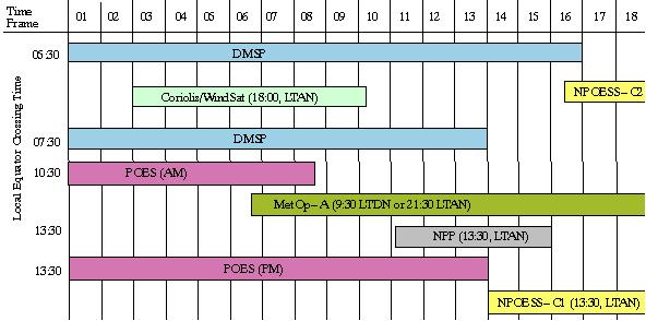
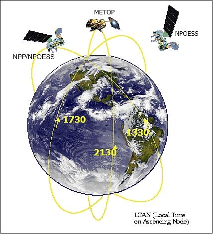
• The first NPOESS satellite (C1) is being planned for launch in 2014 into a sun-synchronous, afternoon polar orbit (13:30 hours LTAN) at an altitude of 828 km to replace the last of NOAA’s POES. spacecraft. Data collected from imaging and atmospheric sounding instruments in this afternoon orbit are critical for global NWP models.
• The NPOESS C-2 satellite is being planned for launch in 2016 to replace the last of the DMSP spacecraft that currently occupy either an early morning (17:30 hours LTAN) or mid-morning orbit to support military operations worldwide. Satellite imagery and atmospheric data from this orbit are critical to support DoD global NWP models and short-term local and regional forecasts that are used for tactical planning on the battlefield.
• NOAA depends on data from the afternoon orbit (13:30 hours LTAN) for critical input into global and regional weather forecast models. The afternoon NPOESS spacecraft will carry advanced technology visible, infrared, and microwave imagers and sounders to deliver higher spatial, temporal, and spectral resolution data enabling more accurate short-term weather forecasts and severe storm warnings. The early morning orbit (1730 LTAN) will provide critical visible and microwave imagery for global cloud forecast models to support DoD’s tactical decisions for air, sea, and ground operations.
• The mid-morning orbit (9:30 hours LTDN or 21:30 hours LTAN) is being occupied by the MetOp satellite series of EUMETSAT (launch of MetOp-A on Oct. 19, 2006, launch of MetOp-B in 2012). The sensor complement of the MetOp series is similar to the one that will fly on NPOESS. The MetOp missions represent a permanent replacement of the NOAA POES satellites in the mid-morning orbit as part of the NOAA/EUMETSAT Initial Joint Polar-orbiting Operational Satellite System (IJPS) agreement.
System Architecture
The NPOESS architecture is built on a foundation of affordability, and three pillars of data quality, data latency, and availability.
- Affordability refers to an over-arching consciousness about cost to preserve the cost benefit to the government for implementing a converged system; some dimensions of cost include the cost for system development and implementation, the balance of system development cost and system Operations and Maintenance cost, and the fiscal year expenditure plan that meets schedule commitments.
- Data quality is characterized in terms of the attributes associated with EDRs (Environmental Data Records), and the products that are delivered to the four US Operational Centrals. These EDRs are generated by the system using raw data from the spaceborne sensors and spacecraft, in conjunction with science algorithms and calibration factors.
- Data latency refers to the time period between the detection of energy by a spaceborne sensor to the delivery of a corresponding EDR. The system was designed to minimize data latency, and hence provide users with timely data.
- Availability refers to both data availability and system availability. Data availability is ensured by the way data is stored throughout the system, on the spacecraft and on the ground, so that it can be retrieved and resent if the first transmittal is not successful. System availability is a measure of how well around-the-clock operations are supported, through the careful deployment of hot spares and fault tolerance of the system. Both types of availability are very high for the NPOESS architecture. 16)
The overall NPOESS system architecture consists of the following segments: 17) 18)
1) NPOESS Space Segment
The operational concept of NPOESS consists of a LEO constellation of two sun-synchronous spacecraft in two orbital planes with equatorial ascending nodal crossing times of 13:30 and 17:30 hours local solar time (LTAN), respectively. Note: The original planning had 3 spacecraft in 3 orbital planes.
LTAN of 13:30 (NPOESS) | LTAN of 17:30 (NPOESS) | LTAN of 13:30 (NPP) |
VIIRS (Visible/Infrared Radiometer Suite) | VIIRS | VIIRS |
CrIS (Cross-track Infrared Sounder) |
| CrIS |
ATMS (Advanced Technology Microwave Sounder) |
| ATMS |
MIS (Microwave Imager/Sounder), C3 | MIS |
|
OMPS (Ozone Mapping and Profiler Suite) |
| OMPS |
SEM-N (Space Environment Monitor-NPOESS) |
|
|
CERES (Clouds and the Earth's Radiant Energy System), C1 |
| CERES |
TSIS (Total Solar Irradiance Sensor), C1 |
|
|
S&RSAT (Search & Rescue Satellite Aided Tracking) | S&RSAT |
|
ADCS (ARGOS Data Collection System) | A-DCS |
|
The space segment is designed to have ample resource margins with the ability to accommodate technology insertion, component changes and performance enhancements. The following resource reservation requirements apply with regard to mass, power, and data rate budgets:
• The spacecraft shall provide additional capacity to accommodate new instruments with a mass equal to 365 kg with no margin
• The spacecraft shall provide additional capacity to accommodate new instruments with power equal to 25% of the total 13:30 S/C payload power as defined at CDR (Critical Design Review) with no margin (320 W)
• The spacecraft shall provide additional capacity to accommodate new instruments with a data rate equal to 25% of the total payload data rate as defined at CDR with no margin (there are two data buses IEEE 1394 and IEEE 1553; the total allocation is at least 3.5 Mbit/s).
Northrop Grumman Corp. successfully completed the Critical Design Audit of the Space Segment for NPOESS in March 2009.
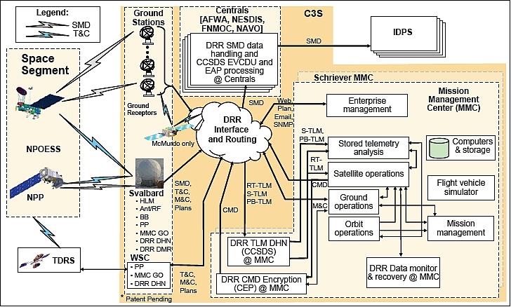
2) C3S (Command, Control and Communication Segment)
The C3S provides all communications with the satellites, and consists of three elements:
• The Ground Station (GS) element
• The Mission Management Center (MMC) element
• The Data Routing and Retrieval (DRR) element.
The DRR objective is to deliver global SMD (Stored Mission Data) to four US Operational Processing Centers (referred to as Centrals or OPCs) for processing and distribution. The Centrals are:
- NOAA/NESDIS (National Environmental Satellite, Data, and Information Service), and NCEP (National Centers for Environmental Prediction)
- AFWA (Air Force Weather Agency)
- FNMOC (Fleet Numerical Meteorology and Oceanography Center)
- NavOceano (Naval Oceanographic Office)
SafetyNet
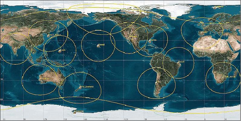
A revolutionary improvement in data retrieval is being implemented for NPOESS. The SafetyNet ground data receptor network will enable users to receive and process NPOESS environmental data in less than 28 minutes from the moment it was captured for 95% of the data, compared to about two hours for the DMSP and POES systems. Considering that space environmental conditions can vary on time scales of tens of minutes, SafetyNet will allow space weather service providers to better support time-critical operations and space- based resource protection. 19)
SafetyNetTM is a patented mission data collection architecture of Northrop Grumman Corporation (NGC). It consists of 15 globally distributed unmanned ground receptors designed to frequently receive stored mission data from NPOESS satellites. The unmanned ground receptors are interconnected and linked to central data processing centers in the United States by commercial fiber optic networks. - Global SMD will be downlinked to the 15 ground stations at Ka-band (26.7 GHz) that will be tied to Centrals via commercial fiber-optic networks. This innovative ground system will deliver 75% of the SMD (daily average) to Centrals within 15 minutes and 95% of the data (daily average) within 26 minutes from the time of on-orbit collection. SMD will be the complete, full resolution data set containing all sensor data and auxiliary data necessary to generate all NPOESS Environmental Data Records (EDRs) at the Centrals. The EDRs are then used to provide timely, accurate environment products tailored to the meet the needs of the Weather Centrals' customers.
Frequency band | Ka-band (26.7 GHz) |
Data storage | Each SafetyNet Receptor designed to store up to 24 hours of mission data |
Data handling | - Ka-band downlink data rates at 150 Mbit/s |
Satellite contacts | Each satellite has an average of 6.2 ground receptor site contacts per orbit |
Fiber optic links | Distribute data to Weather Centrals at 40 Mbit/s |
Ground receptor locations | India, South Africa, Spain, Svalbard (Norway), Guam, Australia, New Zealand, Alaska, California, Florida, Brazil, Chile, South Korea, McMurdo (Antarctica), Hawaii |
Data product | Objective 15-minute product latency 77% of the time |
Latency | - Delivers 95% of data in less than 28 minutes |
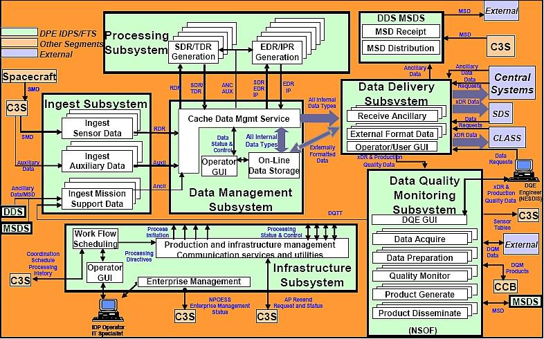
3) IDPS (Interface Data Processing Segment)
Each Central will be equipped with an IDP segment consisting of the necessary data ingest and computational hardware/software to process NPOESS Raw Data Records (RDR) into EDRs, using auxiliary and ancillary data as necessary. Intermediate-level satellite instrument Sensor Data Records (SDRs) will be produced as RDRs are processed into EDRs. The SDRs contain the counts and calibration data at geolocated points. RDRs will also be provided by the IDP for archive and validation purposes. These data products will be available through the Centrals' IDP as retrievable data records. 20) 21)
NPOESS data, including RDRs, SDRs, EDRs, stored raw mission data, stored and real-time telemetry, and stored data from the ADCS (Advanced Data Collection System), will be distributed through the data routing and retrieval component of the NPOESS C3S to the four U.S. Centrals and to the two NPOESS mission management/control centers. The Centrals' IDP will provide sufficient temporary storage capacity (i.e., storage capacity for multiple passes - minimum of 24 hour storage) to store the RDRs/SDRs/EDRs and ancillary data for immediate use in the Centrals' higher-level product applications. NOAA/NESDIS will maintain the long-term archive of NPOESS data. NESDIS will also be responsible for providing the worldwide user community access to near real-time processed NPOESS data and higher-level products via the NESDIS Central Environmental Satellite Computer System (CEMSCS) servers, as well as access to archived NPOESS data via other distributed servers at the three NESDIS Data Centers.
4) NPOESS Broadcast Services
In addition to the space-to-ground transmission of SMD, NPOESS will simultaneously broadcast two continuous real-time data streams, at high and low rates, to suitably equipped field terminals worldwide. These direct broadcast/real-time field terminals will be capable of processing NPOESS RDRs into EDRs by using IDP software appropriate for the type of field terminal. NGST is developing the IDP software that will run on the high-end computer systems at each of the Centrals, as well as the scalable IDP software that will run on the field terminals, including commercial-off-the-shelf systems. The IPO will distribute the non-proprietary IDP field terminal software, software changes, and program updates to field terminal users worldwide.

5) FTS (Field Terminal Segment)
FTS is a sub-segment of the Interface Data Processing Segment (IDPS) and a software product. The FTS hardware is the responsibility of data users and will be purchased, owned, operated, and maintained by DOC, Air Force, Army, Navy, Marine, national and international civil organizations. The FTS will allow users to receive and process the NPOESS continuous broadcast of sensed data via two frequencies with field terminals located on the surface. The HRD (High Rate Data) will be transmitted at X-band (7834 MHz) with a data rate of 20 Mbit/s. The LRD (Low Rate Data) will be transmitted at L-band (1707 MHz) with a data rate of 3.88 Mbit/s. Once the field terminal user receives the data, it is pre-processed to depacketize data. The FTS provides software for fixed or mobile receivers to process regional real-time mission data broadcast from the satellite. 22)
The NPOESS program supports two operational missions, one for global environmental sensing and data product production, and one of the regional direct readout environmental sensing and data product production. The data products produced within the direct readout mission is a subset of those data products produced by the global data set.
IPO data policy is to make a large subset of NPOESS environmental data available free of charge to the global user community. However, to meet US policy requirements for selective data denial, NPOESS will be capable of encrypting selected mission data in all satellite links, excluding the S&RSAT and ADCS real-time downlinks. The overall service spectrum consists of: 23) 24)
1) Onboard acquisition and transmission (broadcast) of telemetry data in real-time to field terminals of the user community.
2) The NPOESS ground segment will acquire and store global and regional environmental imagery, specialized meteorological, climatic, terrestrial, oceanographic, solar-geophysical, and other data in support of DOC/NOAA and DoD/USAF requirements. Once the data is stored, each agency (NASA, NOAA, DoD) will disseminate and conduct further analysis on their own systems as needed.
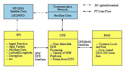
The (ground-based, fixed and mobile) Field Terminal (FT) consists of three elements:
• SPS (Signal Processing Subsystem)
• DPE (Data Processor Element)
• MAS (Mission Application Subsystem).
The FTS concept provides the engineering and application software required to host the program provided data processing element (DPE) software source code and the Field Terminal technical specification defining the minimum required COTS (Commercial-Off-The-Shelf) hardware and software required for satellite direct broadcast signal processing and DPE processing.
Field Terminal (FT): The FT is a stand-alone system that ingests, processes and stores data from NPOESS in near real-time. The FT will ingest real-time mission data from the NPOESS satellites, and produce Raw Data Record (RDR), Sensor Data Record (SDR), Temperature Data Record (TDR) and Environmental Data Record (EDR) products that are provided to the MAS for processing and visualization. The DPE software, a subset of the IDPS (Interface Data Processor Element Segment) software, generates the products, and is described in detail in the IDPS Operations Concept (OPSCON) document. NPOESS responsibility ends with the IDPS output interface.
The Field Terminal service provides a direct readout functionality to the user. This allows each site to generate required xDRs in near real-time based on data received by NPOESS satellites as they pass overhead within the reception field of the FT's antenna. Terminals exist in one of two data rate-dependent configurations, either High Rate Data or Low Rate Data. The HRD systems accept NPOESS X-band data at 20 Mbit/s and produce 50 of the total 56 system EDRs. LRD systems receive data in L-band at 3.88 Mbit/s, and produce 29 of the total system EDRs. Transportable configurations are possible with either the HRD or LRD systems.
The real-time HRD and LRD data streams contain data from various satellite sensors. The FTS creates RDR granules, SDR granules, TDR granules and EDR granules from the HRD or LRD mission data, and associated ancillary and auxiliary data. These products will be delivered to the Mission Application Subsystem (MAS) for postprocessing.
The basic output product from NPOESS will be a collection of EDRs containing the environmental parameters or imagery required by the users. Observational data as well as any ancillary data required to identify or interpret these parameters or images are generally produced by applying an appropriate set of algorithms to Raw Data Records (RDR).
The SPS (Signal Processing Subsystem) receives the NPOESS satellite direct broadcast and processes the CCSDS-formatted link making available Application Packets to the DPE (Data Processor Element). A feature of the NPOESS system design is the ability to selectively enable data access to pre-approved field terminal users. When directed by the US Government, the system will enter into Selective Data Encryption (SDE) mode. The authorized NPOESS users have the ability to access the mission data that has been protected in this way. This requirement is satisfied using commercial grade AES (Advanced Encryption Standard) encryption.
The DPE (Data Processor Element) is the central component of the Field Terminal and is the entity that ingests mission data, ancillary data derived from outside the system, auxiliary data generated within the system in order to produce NPOESS data products. The received mission data are aggregated into raw data records (RDRs) equivalent to NASA level-0 products. Calibration corrections and geolocation is performed to produce sensor data records equivalent to NASA level-1b products. These are further processed to produce NPOESS environmental data products (EDRs) equivalent to NASA level-2 products. The DPE also produces TDRs (Temperature Data Records) associated with microwave-based sensors. These data products along with associated metadata are delivered to the User in an HDF-5 formatted file. The user has the ability, via the Data Delivery subscription service, to request products as a standing request.
NPOESS Spacecraft
The spacecraft size and payload capacity will be similar to the current POES series. The spacecraft design requirements call for a 15 year design life (5 years in storage, 3 years of intermittent pre-launch operation, and 7 years of on-orbit design life performance). Requirements call also for up to 21 days of autonomous operation capability with a goal of 60 days. The requirements on RF data transmission call for a nominal data rate of about 12 Mbit/s, LRD (Low Rate Data) of 3 Mbit/s, with an overall system design capacity of up to 20 Mbit/s. 25)
The spacecraft structure is an upsized version of the 3 m bus used for the EOS-class spacecraft of NASA (Terra, Aqua, Aura). The larger variant NPOESS bus maximizes the available envelope afforded by the more capable 4 m EELV (Evolved Expendable Launch Vehicle) to host existing manifested payloads while affording extra “deck space” for upgrades to existing payloads or new payloads of opportunity as they become available. The structure is designed for LEO weather and environmental missions and employs a highly stable optical bench for hosting of payloads. 26)
To accommodate current as well as emerging technologies, the spacecraft utilizes an advanced open C&DH (Command and Data Handling) architecture employing a plug-and-play approach for electrical interfaces. For low rate sensor payloads, an industry standard MIL-STD-1553 data bus scheme is employed while high data rate payloads can use the advanced FireWire 1394a bus which was developed and qualified for space use by the NPOESS program. Evolving to a standard data bus approach allows both the spacecraft and payloads to design to a single, well-established interface with low risk, similar to the approach employed by computer manufacturers and hardware peripherals. Employing this approach enables new payloads to be added with relative ease versus legacy programs in which electrical and software interfaces were more “craft-like” in nature. If new interfaces emerge in the coming decade, the NPOESS bus has been designed with forethought to accept these new interfaces with the addition of front-end converter slices that can convert the interface for ingest and trafficability within the NPOESS C&DH subsystem.
RF communications: The NPOESS spacecraft hosts a high-rate Ka-band stored mission data link that transmits to the worldwide network of SafetyNetTM receptors that receive NPOESS payload sensor data several times per orbit and delivers processed weather and environmental data to users within 30 minutes. Also employed are an X-band broadcast link for large fixed users and an L-band link for smaller mobile field terminals globally.
In May 2009, the NGC (Northrop Grumman Corporation)-led team successfully completed the CDR (Critical Design Review) for NPOESS. 27)
Overview of NPOESS Satellite Architecture
• NPOESS spacecraft are being designed for Earth observation missions (Ref. 5):
- Large nadir platform for maximum payload accommodation on the EELV launch vehicle
- Optical bench stability to ensure all sensors meet demanding pointing requirements
- Thermally optimized with large coldside access for science payloads
• Plug and play avionics architecture:
- Accommodates the FireWire 1394a bus standard in combination with MIL-STD-1553 for all onboard data handling, unique and emerging payload interfaces
- On-board compression and data selection enables VIIRS imagery and CrIS sounding data access to low rate data field users
- Highly autonomous capability satisfies NPOESS mission requirements
- Advanced 32-bit architecture enables handling of all satellite processing functions
• Overall satellite features:
- 7-year mean mission duration to ensure no operational gaps
- Designed to accommodate over 13 sensors with capacity to transmit 5.4 TByte (half the Library of Congress) a day
- Ka-Band downlink to SafetyNetTM enables the downlink of all collected data with 4x improvement of data latency [95% of collected data delivered as EDRs (Environmental Data Recorders) in 28 min]
- Large on-board recorder capacity and SafetyNetTM architecture provides 99.99% data availability
- Leverages NASA’s EOS (Earth Observation Satellite) heritage and experience.
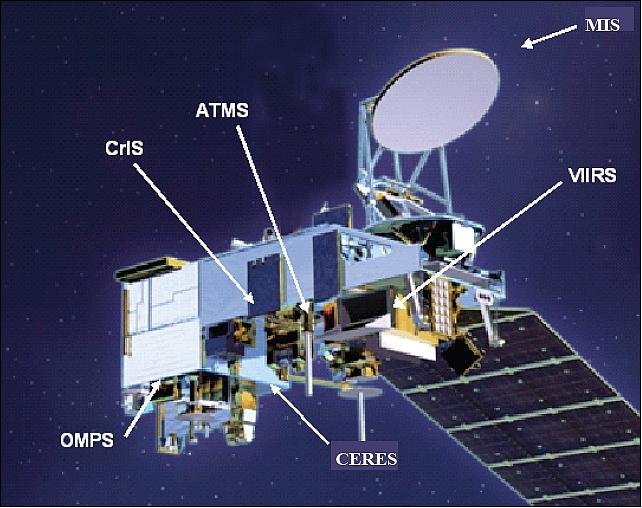
Figure 11: Artist's rendition of the NPOESS 13:30 spacecraft with the primary sensor configuration (image credit: IPO)
Launch
The launch of the NPOESS-C1 spacecraft is scheduled for 2014 to begin replacing the last of the current POES and DMSP satellites.
Orbit
The NPOESS satellites will be developed into three orbital planes (13:30, 17:30, and 21:30 hour equatorial ascending nodal crossing times). Sun-synchronous orbit, nominal altitude = 828 km, inclination =98.7º. The orbit will be maintained with regard to altitude (±17 km), inclination (±0.05º) and nodal crossing times (±10 min).
NPOESS Sensor Complement
A key aspect of the convergence effort is the definition, design, development, and implementation of five critical sensor suites that will fly aboard NPOESS, namely VIIRS, MIS, CrIS, ATMS and CERES (see descriptions under NPP) and OMPS. Each orbit plane contains a unique set of sensor complements (regarding the critical sensors only): 28) 29)
• VIIRS will be accommodated on all three orbits. It contributes to 23 EDRs and is the prime instrument for 18 EDRs.
• MIS (Microwave Imager/Sounder). MIS is a replacement of the original CMIS (Conically-scanning Microwave Imager/Sounder).
Note: The IPO defined a less complex passive microwave radiometer sensor and acquisition strategy to replace the CMIS instrument that was demanifested when the NPOESS program was restructured. The MIS instrument will fly on NPOESS C2-C4 missions to perform key measurements including soil moisture and sea surface winds, as well as other environmental parameters including atmospheric temperature and moisture profiles, and integrated atmospheric moisture and precipitation. 30)
• CrIS and ATMS are selected to fly on the 13:30 and 21:30 orbits. The instruments form a combined cross-track IR/MW sounding suite.
• ATMS (Advanced Technology Microwave Sounder). NASA is developing ATMS instrument for NPP and the NPOESS series.
• OMPS is selected to fly on the 17:30 orbit. OMPS provides 5 ozone EDRs.
VIIRS (Visible/Infrared Imager and Radiometer Suite)
Raytheon Santa Barbara Remote Sensing (SBRS) is the prime contractor for this instrument to NGST. VIIRS is an advanced, modular, multi-channel imager and radiometer (of OLS, AVHRR/3, MODIS, and SeaWiFS heritage) with the objective to provide global observations (moderate spatial resolution) of land, ocean, and atmosphere parameters at high temporal resolution (daily). 31) 32) 33) 34) 35) 36)
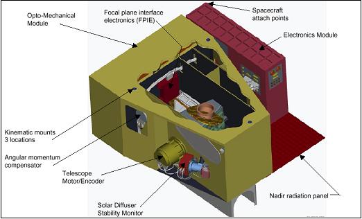
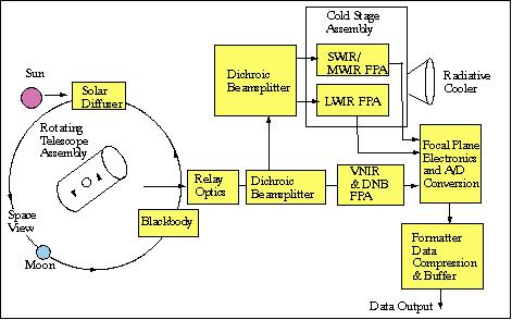
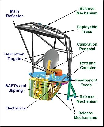
VIIRS is a multispectral (22-band) opto-mechanical radiometer, employing a cross-track rotating telescope fore-optics design (operating on the whiskbroom scanner principle), to cover a wide swath. The rotating telescope assembly (RTA of 20 cm diameter) concept of SeaWiFS heritage allows a low straylight performance. An observation scene is imaged onto three focal planes, separating the VNIR, SWIR/MWIR, and TIR energy - covering a spectral range of 0.4 - 12.5 µm. The VNIR FPA (Focal Plane Array) has nine spectral bands, the SWIR/MWIR FPA has eight spectral bands, and the TIR FPA four spectral bands. The integral DNB (Day Night Band) capability provides a very large dynamic range low-light capability in all VIIRS orbits. The detector line arrays [16 detectors in each array for the SWIR/MWIR and TIR bands, 32 detectors in the array for the VNIR and DNB (Pan) bands] of the whiskbroom scanner are oriented in the along-track direction. This arrangement provides a parallel coverage of 11.87 km along-track in one scan sweep (cross-track direction). The wide along-track coverage permits sufficient integration time for all cells in each scan sweep. One cross-track scan period of RTA is 1.786 s in length. The data quantization is 12 bits (14 bit A/C converters for lower noise).
Typical data products (types) of VIIRS include atmospheric, clouds, earth radiation budget, clear-air land/water surfaces, sea surface temperature, ocean color, and low-light visible imagery. A swath width of 3000 km is provided (corresponding to FOV=±55.84º) with a spatial resolution for imagery related products of no worse than 0.4 km to 0.8 km (nadir to edge-of-scan). The radiometric bands provide a resolution about twice in size to the imagery bands. Note: Most derived data products will be produced at somewhat coarser resolutions by aggregation of on-board data.

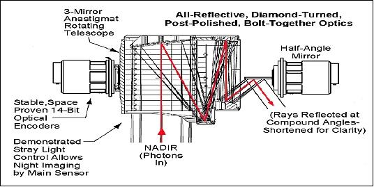
The VIIRS instrument design employs an all-reflective optics assembly taking advantage of recent optics advances: a) single 4 mirror imager, b) 2 dichroics and 1 fold, c) aluminum DPT-bolt together technology (DPT = Diamond Point Turning). A rotating off-axis and afocal TMA (Three Mirror Anastigmatic) telescope assembly is employed [Note: The telescope rotates 360º, thus scanning the Earth scene, and then internal calibration targets.]. The aperture of the imaging optics is 18.4 cm in diameter, the focal length is 114 cm (f/5.97). The VIIRS optical train consists of the fore optics (TMA), the aft optics [an all-reflective FMA (Four Mirror Anastigmatic) imager], and the back-end optics, which include microlenses for the cooled focal planes.
A total of 22 spectral bands have been selected as defined in Table 3. VIIRS features band-to-band registration for all bands (optical alignment of all FPAs). A total of three focal planes and four FPAs (Focal Plane Arrays) cover the spectral range of the instrument, one FPA for DNB (Day-Night Band), one for VNIR, SWIR/MWIR, and TIR. The DNB spectral range of 0.5-0.9 µm CCD detector features four light-sensitive areas (3 with TDI, one without) and near-objective sample spacing.
The VNIR FPA employs a PIN (Positive Insulator Negative) diode array/ROIC (Readout Integrated Circuit) design collocated with the DNB monolithic CCD. All detectors in the SWIR/MWIR/TIR regions employ photovoltaic (PV) detectors with an element spacing of 12 µm. A ROIC (Readout Integrated Circuit) at each FPA provides improved noise levels and built-in offset correction. A cryogenic module (three-stage radiative cooler) provides FPA cooling.
A single-board instrument computer provides a processing capability including data aggregation, data compression [lossless (2:1 Rice compression) and lossy (JPEG) algorithms are used], and CCSDS data formatting.
Calibration is performed with three on-board calibrators: a) a solar diffuser provides full aperture solar calibration, a solar diffuser stability monitor, and c) a blackbody. Instrument calibration of VIIRS is based on that of the MODIS instrument: 37) 38) 39)
• VNIR: 1) View of a spectralon plate at the poles every few days; 2) Deep space view
• SWIR/MWIR/TIR: 1) View of blackbody every scan; 2) Deep space view
The VIIRS instrument has a mass of about 275 kg, power of ~ 240 W (operational average), and a size of 134 cm x 141 cm x 85 cm. The data rate is 10.5 Mbit/s (high rate mode) and 8 Mbit/s (average rate) mode with 10:1 JPEG compression). The VIIRS instrument features a SBC (Single Board Computer) for all instrument operations and control; it communicates with the S/C via an IEEE 1394a cable interface.
Some operational features of VIIRS:
• All functions are individually commandable
• Macro commands (stored sequences, all macros are reprogrammable) simplify the commanding and reduce the uplink data
• Time-tagged commands allow delayed execution (provides for 30 days autonomous operations)
• The swath widths and locations are individually programmable by band (improved resolution views of selected target near nadir)
• Diagnostic mode features improved versatility
Band | Center wave (µm) | Bandwidth (µm) | Comment (driving EDR observation requirements) |
VNIR (Visible Near-Infrared) spectral region, use of Si detectors in FPA | |||
DNB | 0.70 | 0.40 | Day Night Band, broad bandwidth maximizes signal (essential nighttime reflected band) |
M1 | 0.412 | 0.02 | Ocean color, suspended matter, net heat flux, mass loading |
M2 | 0.445 | 0.018 | Ocean color, suspended matter, net heat flux, mass loading |
M3 | 0.488 | 0.02 | Ocean color EVI, surface type, aerosols suspended matter, net heat flux, mass loading |
M4 | 0.555 | 0.02 | Ocean color, surface type, suspended matter, net heat flux, mass loading |
I1 | 0.640 | 0.05 | Imagery, NDVI, cloud mask/cover, cloud optical properties, surface type, albedo, snow/ice, soil moisture |
M5 | 0.672 | 0.02 | Ocean color, aerosols, suspended matter, net heat flux, littoral transport, mass loading |
M6 | 0.746 | 0.015 | Ocean color, mass loading |
I2 | 0.865 | 0.039 | Imagery NDVI (NDVI heritage band), snow/ice, surface type, albedo |
M7 | 0.865 | 0.039 | Ocean color, cloud mask/cover, aerosols, soil moisture, net heat flux, mass loading |
SWIR (Short-Wave Infrared) spectral region, use of PV (Photovoltaic) HgCdTe detectors | |||
M8 | 1.24 | 0.02 | Cloud optical properties (essential over snow/ice), active fires |
M9 | 1.378 | 0.015 | Cloud mask/cover (thin cirrus detection), aerosols, net heat flux |
M10 | 1.61 | 0.06 | Aerosols, cloud optical properties, cloud mask/cover (cloud/snow detection), active fires, soil moisture, net heat flux |
I3 | 1.61 | 0.06 | Imagery snow/ice (cloud/snow differentiation), surface type, albedo |
M11 | 2.25 | 0.05 | Aerosols (optimal aerosol optical thickness over land), cloud optical properties, surface type, active fires, net heat flux |
MWIR (Mid-Wave Infrared) spectral region, use of PV (Photovoltaic) HgCdTe detectors | |||
I4 | 3.74 | 0.38 | Imagery (identification of low and dark stratus), active fires |
M12 | 3.70 | 0.18 | SST (Sea Surface Temperature), cloud mask/cover, cloud EDRs, surface type, land/ice surface temperature, aerosols |
M13 | 4.05 | 0.155 | SST (essential for skin SST in tropics and during daytime), land surface temperature, active fires, precipitable water |
TIR (Thermal Infrared) spectral region, use of PV (Photovoltaic) HgCdTe detectors | |||
M14 | 8.55 | 0.3 | Cloud mask/cover (pivotal for cloud phase detection at night, cloud optical properties |
M15 | 10.763 | 1.00 | SST, cloud EDRs and SDRs (Science Data Records), land/ice surface temperature, surface type |
I5 | 11.450 | 1.9 | Imagery (nighttime imagery band) |
M16 | 12.013 | 0.95 | SST, cloud mask/cover, land/ice surface temperature, surface type |
DNB (Day-Night Band) FPA | VNIR FPA | SWIR/MWIR FPA | TIR FPA |
One broadband | 9 bands | 8 bands | 4 bands, 1 with TDI |
CCD detector | Si PIN diodes | PV HgCdTe detector | PV HgCdTe detector |
FPIE (Focal Plane Interface Electronics) | ROIC (Readout Integrated Circuit) | ROIC | ROIC |
Filter/Bezel | Filter/Bezel | Si micro-lens array | Ge micro-lens array |
Tops = 253 K | Tops = ambient | Filter/Bezel | Filter/Bezel |
|
| Tops = 80 K | Tops = 80 K |
Some key EDRs of VIIRS: 40)
• SST (Sea Surface Temperature). VIIRS is capable to provide a nadir resolution of 750 m (by aggregating detectors 3:l in-track near nadir, 2:l in-track aggregation out to a 2,000 swath, and 1:1 out to 3,000 km) to simultaneously optimize spatial resolution and noise performance. - The SST solution combines the traditional long-wave infrared (LWIR) split window with a second split window in the mid-wave infrared (MWIR) for a globally robust SST algorithm. The MWIR split window has a higher transmissivity than the traditional LWIR split window for improved atmospheric correction. The low-noise design is operable day and night with 0.25 K precision, and 0.35 K total measurement uncertainty (rms error).
• Imagery and cloud detection/typing. The imagery solution provided on VIIRS includes six high-resolution bands and an additional 16 moderate-resolution bands. One of these, a reflective panchromatic band (DNB), is operable in low-light conditions down to a quarter moon. A swath with of 3000 km is provided.
• Soil moisture. A VIIRS/CMIS data fusion solution was derived. The approach combines the fine spatial resolution of VIIRS with traditional coarser-resolution microwave-derived soil moisture retrievals to achieve excellent results over both open and partially vegetated scenes. The estimation procedure involves two steps: 1) CMIS estimates soil moisture at coarse spatial resolution. This involves inversion of dual-polarized microwave brightness temperatures. 2) CMIS-derived low-resolution soil moisture is linked to the scene optical parameters, such as NDVI (Normalized Difference Vegetation Index), surface albedo, and LST (Land Surface Temperature). The linkage of the microwave-derived soil moisture to NDVI, surface albedo and LST is based on the “Universal Triangle” approach of relating land surface parameters. The three high-resolution optical parameters are aggregated to microwave resolution for the purpose of building the linkage model. The linkage model, in conjunction with high-resolution NDVI, surface albedo, and LST, is then used to disaggregate microwave soil moisture into high-resolution soil moisture.
DNB Overview in VIIRS
The DNB will measure VIS radiances from the Earth and atmosphere (solar/lunar reflection and both natural and anthropogenic nighttime light emissions) during both day and night portions of the orbit. In comparison to the OLS (Operational Linescan System) of the DMSP series, some of the DNB channel improvements include 1) reduced instances of pixel saturation, 2) a smaller IFOV, leading to reduced spatial blurring, 3) superior calibration and radiometric resolution, 4) collocation with multispectral measurements on VIIRS and other NPOESS sensors, 5) and generally increased spatial resolution and elimination of cross-track pixel size variation. 41)
The DNB is implemented as a dedicated focal plane assembly (FPA) that shares the optics and scan mechanism of the other VIIRS spectral bands. This integral design approach offers lower overall system complexity, cost, mass, and volume compared to a separate DNB sensor. Unlike the OLS, the DNB will feature radiometric calibration, with accuracy comparable to the other VIIRS spectral bands.
To achieve satisfactory radiometric resolution across the large dynamic range (seven orders of magnitude) of day/night radiances encountered over a single orbit, the DNB selects its amplification gain dynamically from three simultaneously collecting stages (groups of detectors residing upon the same FPA). The stages detect low-, medium-, and high-radiance scenes with relative radiometric gains of 119,000:477:1 (high:medium:low gain). Each of the three stages covers a radiance range of more than 500:1, so that the three together cover the entire required radiance range with generous overlap. Two identical copies of the high-gain stage are provided, which improves the SNR at very low signal levels and allows for the correction of pixels impacted by high-energy subatomic particles. The scene is scanned sequentially such that each scene is imaged by all three gains virtually simultaneously.
The signals from all gain stages are always digitized, using 14 bits for the high-gain stage and 13 bits for the medium- and low-gain stages. This fine digitization assures the DNB will have a sufficiently fine radiometric resolution across the entire dynamic range. Logic in the VIIRS Electronics Module (EM) then selects, on a pixel-by-pixel basis, the most appropriate of the three stages to be transmitted to Earth. In general, the VIIRS EM logic chooses the most sensitive stage in which the pixel is not saturated. This imaging strategy produces nonsaturated calibrated radiances in bright areas, and data with a lower dynamic range in the darkest areas with less SNR and radiometric accuracy.
In summary, the VIIRS DNB feature will bring significant advances to operational and research applications at night (over OLS operations) due to the increased sensitivity of the instrument.
MIS (Microwave Imager/Sounder)
The MIS instrument of NPOESS will continue the legacy measurements of the DMSP SSMIS (Special Sensor Microwave Imager/Sounder) and the SSM/I (Special Sensor Microwave Imager) instruments of the DMSP satellite series that are critical to operational weather forecasting, climate monitoring and earth science. 42)
In June 2008, the IPO competitively selected NRL to build the MIS instrument because of its demonstrated experience and knowledge developing the first spaceborne polarimetric microwave radiometer, WindSat, operating successfully since 2003 on the Coriolis mission. The first MIS sensor is scheduled to fly aboard the second NPOESS spacecraft (C2) expected to launch in 2016.
• In May 2009, NRL's Spacecraft Engineering Department and Remote Sensing Division successfully completed the System Requirements and Design Review (SRDR) of the MIS project
• NRL is now proceeding toward Preliminary Design Review (PDR), which is scheduled for spring of 2010 43)
• The CDR (Critical Design Review) is scheduled for 2011.
The objective of the MIS instrument is to collect global microwave radiometry and sounding data to produce microwave imagery and other meteorological and oceanographic data. It is the primary instrument for satisfying 17 EDRs (Environmental Data Records). The MIS data will be provided on NPOESS spacecrafts C2 (2016), C3, and C4.
The MIS concept design includes (Ref. 5):
• 6 GHz to 183 GHz measurement range
• 39 channels; 12 feedhorns
- Core imaging channels: 10 VH; 18 VH, 23 VH; 37 VH; 89 VH
- Atmospheric sounding: 50.3 – 60 GHz; 166 & 183.31 GHz
- Low frequency: 6.8 VH
- Polarimetric channels: 10 PM or LR; 18 PMLR; 37 PM
• Upper Air Sounding: 60 – 63 GHz [FM2 on C3] on going trade study
• 1.8 m main reflector, deployable structure
• Swath width: ~1,700 km
• Calibration: 2-point
• Instrument mass: 475 kg
• Data rate: 500 kbit/s
• 357 W average operational power consumption.
• Conical scanning at 31.6 rpm
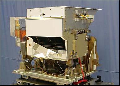
CrIS (Cross-Track Infrared Sounder)
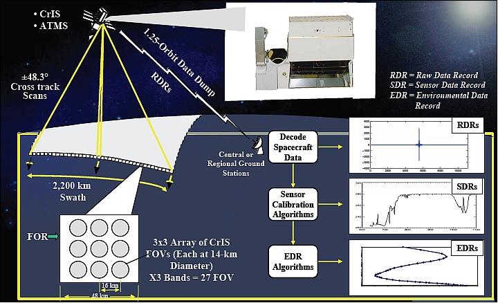
The FTS (Fourier Transform Spectrometer) instrument is being developed by ITT Aerospace/Communications Division of Ft. Wayne, IN, as the prime contractor. CrIS, of HIRS/4 (POES) and AIRS (Aqua) heritage, is a high-spectral and high-spatial resolution infrared sounder for atmospheric profiling applications. The overall objective is to perform daily measurements of Earth's upwelling infrared radiation to determine the vertical atmospheric distribution (surface to the top of the atmosphere) of temperature (profiles to better than 0.9 K accuracy in the lower troposphere and lesser accuracy at higher altitudes), moisture (profiles to better than 20-35% accuracy depending on altitude) and pressure (profiles to better than 1.0% accuracy ) with an associated 1.0 km vertical layer resolution. The Michelson interferometer sounder has over 1300 spectral channels, it covers a spectral range of 650-2550 cm-1 (or 3.9 to 15.4 µm), with a spectral resolution of 0.6525 cm-1 (LWIR), and a ground spatial resolution (IFOV) of 14.0 km. The IFOVs are arranged in a 3 x 3 array. The swath width is 2300 km (FOV of ±48.33º).
The “unapodized spectral resolution” requirement is defined as I/(2L), where L is the maximum optical path difference from ZOND (Zero Path Difference) to MPD (Maximum optical Path Difference). The on-axis unapodized spectral resolution for each spectral band shall be ≤to the values given in Table 5. Since L determines the unapodized spectral resolution, the nominal value for L is also given in the table. 44)
Requirement/Spectral band | LWIR (TIR) | MWIR | SWIR |
Channel center wavenumber range | 650-1095 cm-1 | 1210-1750 cm-1 | 2155-2550 cm-1 |
No of channels | 713 | 433 | 159 |
Unapodized spectral resolution, nominal L | ≤ 0.625, 0.8 cm | ≤ 1.25, 0.4 cm | ≤ 2.5, 0.2 cm |
Absolute spectral uncertainty | < 10 (5) PPM | < 10 (5) PPM | < 10 (5) PPM |
Characterize self-apodized ILS for each spectral bin | Yes | Yes | Yes |
ILS (Instrument Line Shape) shape uncertainty | < 1.5% FWHM | < 1.5% FWHM | < 1.5% FWHM |
ILS shape stability over 30 days | < 1% FWHM | < 1% FWHM | < 1% FWHM |
The flight configuration for the CrIS DPM (Detector Preamplifier Module) consists of three spectrally separate (SWIR, MWIR and LWIR) FPAAs (Focal Plane Array Assemblies), three (SWIR, MWIR and LWIR) signal flex cable assemblies, a warm signal flex cable/vacuum bulk head assembly, and the DPM warm electronics CCAs (Circuit Card Assemblies). The FPAAs are cooled to cryogenic temperature (98 K SWIR, MWIR, 81 K for LWIR) by the detector cooler module. The cryogenic portions of the DPM (FPAAs, and signal flex cable assemblies) mate to the ambient temperature portions of the DPM (warm signal flex cable assembly and the ambient temperature portions of the transimpedance amplifier, mounted within the CCAs) through the vacuum bulk head assembly mounted on the detector cooler assembly housing. 45)
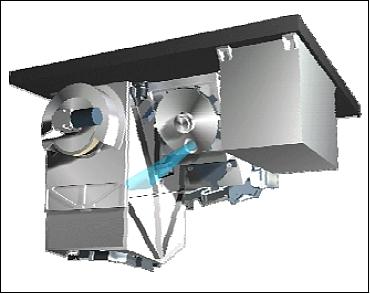
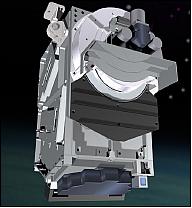
The baseline CrIS instrument design consists of nine independent single-function modules: [telescope, optical bench, aft-optics, interferometer (FTS), ICT (Independent Calibration Target), SSM (Scene Selection Module), detectors, cooler, processing and control electronics, and instrument structure]. 46)
• 8 cm clear aperture
• A collimator is used to perform the spatial and spectral characterizations
• 4-stage split-patch passive cooler (81 K for LWIR patch temperature, 98 K for MWIR/SWIR patch)
• High-performance PV (photovoltaic) detectors
• 3 x 3 arrays (14 km IFOVs)
• Three spectral bands (SWIR, MWIR, TIR), co-registered so that the FOVs of each band see the radiance from the same region of the Earth's atmosphere
• All-reflective telescope
• Proven Bomem plane-mirror Michelson interferometer with dynamic alignment
• Deep-cavity internal calibration target based on MOPITT design
• Two-axis scene selection module with image motion compensation
• A modular design (allowing for future addition of an active cooler and >3 x 3 arrays
Spectral bands | Total of 1305 channels |
Spectral resolution: |
|
Band-to-band co-registration | < 1.4% |
Number of IFOVs | 3 x 3 at 14 km diameter for each band |
IFOV diameter | 14 km |
Absolute radiometric uncertainty | <0.8% (SWIR), <0.6% (MWIR), <0.45% (TIR) |
Radiometric stability | <0.65% (SWIR, <0.5% (MWIR), <0.4% (TIR) |
Instrument size | 71 cm x 80 cm x 95 cm |
Instrument mass, power, data rate | < 152 kg, < 124 W (max), 1.44 Mbit/s (average), 1.75 Mbit/s (max) |
The primary data product of the CrIS instrument are interferograms collected from 27 infrared detectors that cover 3 IR bands and 9 FOVs. 47)
Data of CrIS will be combined in particular with those of ATMS to construct atmospheric temperature profiles at 1 K accuracy for 1 km layers in the troposphere and moisture profiles accurate to 15% for 2 km layers. 48)
CrIS + ATMS = CrIMSS (Cross-Track Infrared Microwave Sounding Suite)
CrIS is designed to work in unison with ATMS (Advanced Technology Microwave Sounder); together they create CrIMSS (Cross-track Infrared Microwave Sounding Suite). The objective of CrIMSS is to provide global 3D soundings of atmospheric temperature, moisture and pressure profiles. In addition, CrIMSS has the potential to provide other surface and atmospheric science data, including total ozone and sea surface temperature. ATMS provides high spatial resolution microwave data to support temperature and humidity sounding generation in cloud covered conditions. Note: See ATMS description under NPP.
Primary temperature profiles | Secondary total ozone |
Moisture profiles | Sea Surface Temperature (SST) |
OMPS (Ozone Mapping and Profiler Suite)
OMPS is a limb- and nadir-viewing UV hyperspectral imaging spectrometer, designed and developed at BATC (Ball Aerospace & Technologies Corp.), Boulder, CO. The objective is to measure the total amount of ozone in the atmosphere and the ozone concentration variation with altitude. OMPS is of SBUV/2, TOMS and GOME heritage. Also, the OMPS limb-sounding concept/technology was already tested with ISIR (Infrared Spectral Imaging Radiometer) flown on Shuttle flight STS-85 (Aug. 7-19, 1997) and with SOLSE/LORE flown on STS-87 (Nov 19 - Dec. 5, 1997). The vertical resolution requirement demands an instrument design to include a limb-viewing sensor in addition to a heritage-based nadir-viewing sensor. 49)
Basic requirement | Measurement parameter | Requirement |
1) Global daily maps of the amount of ozone | Horizontal cell size | 50 km @ nadir |
2) Provision of volumetric ozone concentration | Vertical cell size | 3 km |
The OMPS instrument design features two coregistered spectrometers in the OMPS nadir sensor and a limb sensor, measuring the limb scatter in the UV, VIS, and NIR. The instrument has a total mass of 68 kg, an average power consumption of 108 W, a size of 0.35 m x 0.54 m x 0.56 m, and a data rate of 165 kbit/s.
1) Nadir-Viewing Instrument
The nadir sensor wide-field telescope feeds two separate spectrometers, a) for total column observations (mapper) and b) for nadir profiling observations. The total column spectrometer (300-380 nm spectral range, resolution of 0.42 nm) has a 2800 km cross-track swath (FOV = 110º and an along-track slit width of 0.27º) divided into 35 IFOVs of nearly equal angular extent. The CCD pixel measurements from its cross-track spatial dimension are summed into 35 bins. The summed bins subtend 3.35º (50 km) at nadir and 2.84º at ±55º. The along-track resolution is 50 km at nadir due to spacecraft motion during the 7.6 second reporting period. Measurements from this spectrometer are used to generate total column ozone data with a resolution of about 50 km x 50 km at nadir.
The nadir profile spectrometer (250-310 nm) has a 250 km cross-track swath corresponding to a single cell (cross-track FOV = 16.6º, and 0.26º along-track slit width). Co-registration with the total column spectrometer provides the total ozone, surface and cloud cover information needed for nadir profile retrievals. All of the cross-track pixels are binned spatially to form a single cell of 250 km x 250 km. Some instrument parameters are: 51)
- The telescope is a three mirror, near telecentric, off-axis design. The FOV is allowed to curve backward (concave in the anti-ram direction) by 8.5º at 55º cross-track in order to maintain straight entrance slits for the spectrometers. The mirrors are made with a glass which matches the thermal expansion of Titanium, are coated with an enhanced aluminum, and have an rms surface roughness of < 15Å.
- Each of the 2 spectrometers has a CCD detector array, a split column frame transfer CCD 340 x 740 (column x row) operated in a backside illuminated configuration. The pixel pitch is 20 µm in the column (spectral) dimension and 25 µm in the row (spatial) dimension and every pixel in both the active and storage regions contains a lateral overflow antiblooming structure integrated into a 4-phase CCD architecture.
- Both spectrometers sample the spectrum at 0.42 nm, 1 nm FWHM end-to-end resolution
- Electronics: a) CCD preamplifier electronics in sensor housing, b) main electronics box performs A/D conversion and on-orbit pixel correction
- The OMPS nadir instrument has a mass of 12.5 kg and a size of 31 cm x 32 cm x 20 cm.
Polarization compensators are used to reduce polarization sensitivity for both Nadir instruments. Long-term calibration stability is monitored and corrected by periodic solar observations using a “Working” and “Reference” reflective diffuser system (similar to that successfully deployed on the TOMS sensors).
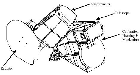
2) Limb Profiler
The limb profiler consists of the following major elements: telescope, the spectrometer, and the calibration & housing mechanism. It uses a single prism to disperse three vertical slits directed along-track, each separated by 250 km at the limb tangent point (one slit views in the orbital plane and the other two slits view to either side of the orbital plane). The vertical slits are separated by 4.25° across track corresponding to 250 km at the tangent points. Each slit has a vertical FOV of 1.95° corresponding to 112 km at the limb to cover altitudes from 0 to 60 km in the atmosphere and also allow for pointing errors, orbital variation, and the Earth's oblateness. Individual pixels on the CCD are spaced every 1.1 km of vertical image and have a vertical resolution of 2.2 km. The instrument uses prism spectrometers to cover the spectral range from 290 nm to 1000 nm. To accommodate the very high scene dynamic range, these slit images pass through a beam splitter to divide the scene brightness into three brightness ranges. As a result there are nine limb images of the dispersed slits on the CCD. The measured limb radiances in the ultraviolet, visible, and near-infrared provide data on ozone, aerosols, Rayleigh scattering, surface and clouds that are used to retrieve ozone profiles from the tropopause to 60 km. 52)
Some limb sensor parameters: The sensor consists of a telescope with three separate cross-track fields of view of the limb, a prism spectrometer covering 290 to 1000 nm, and a solar-diffuser calibration mechanism. The sensor provides 2.2 km vertical resolution profiles of atmospheric radiance with channel spectral resolutions (FWHM) ranging from 0.75 nm at 290 nm to 25 nm at 1000 nm and handles the demanding spectral and spatial dynamic range (4-5 orders in magnitude variation) of the limb-scattered solar radiation with the required sensitivity for ozone retrievals (polarization compensators are also used). The large scene dynamic range is accommodated by using two separate apertures in each telescope, producing two optical gains, and by using two integration times, producing two electronic gains. All six spectra (resulting from three slits viewed through two apertures) are captured on a single CCD FPA. The window above the detector is coated with filters for the ultraviolet and visible regions of the spectra to reduce stray light. The limb sensor has a 38 second reporting period (corresponding to 250 km along-track motion) that includes multiple interspersed exposures at long and short integration times.
Limb-viewing measurements of scattered UV sunlight can be registered in altitude if the altitude errors correspond to a rigid vertical shift, if the instrument measures radiances dominated by single Rayleigh scattering at altitudes where good temperature and pressure data are available from another source. 53)
The staring spectrometer architecture and hyperspectral coverage eliminate the need for any continuous-action mechanisms, increasing the reliability of the sensor.
OMPS calibration: Solar illuminated diffusers are used for radiometric and spectral calibrations (two diffusers for each sensor). The working diffuser is used weekly and the reference diffuser is used twice annually to monitor the on-orbit degradation of the working diffuser.
The OMPS program will create five ozone data EDR products:
• Total ozone column: High performance total column environmental data record
• Nadir ozone profile: Heritage SBUV/2 nadir profile data records
• Limb ozone profile: High performance ozone profile product
• Infrared total ozone: data records from CrIS (Cross-track Infrared Sounder) radiances.
• Calibrated radiances: Heritage TOMS V7 total column data records
Secondary OMPS products are: SO2 index, aerosols (index and profile), UV-B radiance on Earth's surface, NO2, surface albedo, and cloud top height.
Parameter | Nadir Total Column | Nadir Profile | Limb Soundings |
Spectral range | 300-380 nm | 250-310 nm | 290-1000 nm |
Spectral radiance range [photons/(s cm2 sr nm)] | 9 el 3 (380 nm) | 2 el 3 (310 nm) | 9 el 3 (600 nm) |
Minimum SNR | 1000 | 35 (252 nm) | 320 (290 nm at 60 km) |
Integration time | 7.6 s | 38 s | 38 s |
Spectral resolution | 1 nm FWHM | 1 nm FWHM | 2.8-54 nm FWHM |
FOV | 110º x 1.0º (cross-track x along-track) | 16.6º x 0.26º | 8.5º x 1.9º (3 sets) |
Cell size | 49 km x 50 km (nadir) | 250 km x 250 km (single cell at nadir) | 1 km vertical sampling interval |
Revisit time | Daily |
| 4 days (average) |
Swath | 2800 km | 250 km | 3 vertical slits along-track and |
CERES (Cloud and Earth Radiant Energy System)
The CERES instrument is described under NPP.
Auxiliary Payloads of NPOESS
In addition to the above payloads, some auxiliary sensors/payloads are planned to fly onboard NPOESS.
TSIS (Total Solar Irradiance Sensor)
The TSIS instrument is of TIM (Total Irradiance Monitor) and SIM (Spectral Irradiance Monitor) heritage, flown on the SORCE (Solar Radiation and Climate Experiment) mission of NASA (launch Jan. 25, 2003). TIM is also scheduled to fly on the Glory mission of NASA (launch in the fall of 2010). TSIS is a total solar irradiance monitor plus a 0.2-2 µm solar spectral irradiance monitor. The objective is to measure the variability in the sun's radiative output.
The TSIS instrument consists of:
• TIM (Total Irradiance Monitor), to measure the total solar irradiance
• SIM (Spectral Irradiance Monitor) to measure the spectral irradiance in the 200 to 2000 nm range
• TPS (Thermal Pointing Monitor) to integrate the thermal and mechanical designs for sun-staring and calibration.
Background
The TSIS instrument package had been canceled during the 2006 restructuring period of the NPOESS program. In the spring of 2008, TSIS was restored by the NPOESS Executive Committee to fly on NPOESS since the sensor was considered critical in monitoring the global climate change. 54) 55)
NOAA has transferred the responsibility and the funding to NASA to manage the development and delivery of the TSIS to the Mission System Contractor for the NPOESS C1 Mission. The fundamental requirement for TSIS on NPOESS C1 is to make precise and accurate measurements of TSI and SSI and connect them to previous TSI and SSI measurements to form a long-term climate record. The TSI measurements shall have an absolute accuracy of 0.01% (100 parts per million) based on Solar Irradiance (SI) units and shall have a relative accuracy of 0.001% per year. The SIM requirement is to make SSI measurements with a combined standard uncertainty of less than 0.1% and a long-term relative accuracy of 0.03%.
In May 2008, NASA awarded a contract to LASP (Laboratory for Atmospheric and Space Physics) of the University of Colorado, Boulder to procure the TSIS instrument. The TSIS instrument will also be operated remotely aboard NPOESS from LASP. The PI (Principal Investigator) of TSIS is Peter Pilewskie of LASP. 56)
ADCS (Advanced Data Collection System)
The ADCS relays meteorological and other data transmitted from in-situ groundbased data collection platforms including buoys, free floating balloons, and remote weather stations. NPOESS spacecraft will carry the upgraded ARGOS-3/4 data collection system that will provide two-way messaging capabilities for users to command and manage platform transmitters and sensors, as well as receive data efficiently from their platforms.
S&RSAT (Search & Rescue Satellite Aided Tracking)
NPOESS will continue the NOAA tradition of SARSAT service provision. The SARSAT receives distress signals from EPIRBs (Emergency Position Indicating Radio Beacons) on international distress frequencies and retransmits them to local user terminals for action by appropriate government agencies. - The redesigned S&RSAT subsystems on NPOESS will only support EPIRBs transmitting at 406 MHz.
SEM-N (Space Environment Monitor – NPOESS):
SEM-N is a compliment of three space particle sensors to be flown on the NPOESS missions which will take measurements to produce space environment data products for the near-Earth environment. Both the instrument hardware and the ground-processing algorithms are based on heritage capabilities from DMSP, POES and NASA. SEM-N is the primary instrument for 5 EDRs (Environmental Data Records). 57)
The JHU/APL (Johns Hopkins University/Applied Physics Laboratory) was awarded a contract to develop the SEM-N instrument suite. The nominal suite consists of three distinct sensors that address NPOESS requirements:
• SSJ5 (Special Sensor J5): a low-energy electron and ion spectrometer addressing the energy range from 50 eV to 20 keV
• EPS (Energetic Particle Spectrometer): a medium energy electron (positive ion) detector covering the energy range from 30 keV to 2.5 MeV (> 6.9 MeV)
• HES (High Energy Sensor): an omnidirectional high-energy ion detector for measuring particles within the energy range of 15 MeV to 500 MeV.
Background
In 2006, the SESS (Space Environment Sensor Suite) instruments were demanifested from NPOESS and replaced by SEM-N (Space Environment Monitor - NPOESS). These fewer and less capable sensors caused the following impacts on NPOESS-era requirements and products: 58)
- Auroral boundary, auroral energy deposition, and suprathermal to auroral particles products would be retained
- Energetic ions and medium energy charged particles would be degraded
- auroral imagery, electric fields, electron density profile, geomagnetic field, in-situ plasma fluctuation and temperature, ionospheric scintillation, and neutral density profile products would be lost.
References
2) Presidential Decision Directive/NSTC-2, May 5, 1994, URL: http://www.npoess.noaa.gov/index.php?pg=presdir
3) J. D. Cunningham, F. L. Ricker, C. S. Nelson, “The National Polar-orbiting Operational Environmental Satellite System, Future U.S. Operational Earth Observation System,” IEEE/IGARSS, Toulouse, France, Jul. 21-25, 2003
4) W. G. Pichel, J. McGuire, D. Taube, “User Requirements for an Ocean Observation Satellite System,” Proceedings of IGARSS/IEEE 2001, Sydney, Australia, July 9-13, 2001
5) Allan Webb, “NPOESS Program Overview and Status,” June 16, 2009
6) “Joint Polar Satellite System,” NOAA/NESDIS Newsletter 4, 2010, URL: http://www.nesdis.noaa.gov/pdf/jpss.pdf
7) “Restructuring the National Polar-orbiting Operational Environmental Satellite System,” earthzine, Feb. 23, 2010, URL: http://www.earthzine.org/2010/02/23/restructuring-the-national-polar-orbiting-operational-environmental-satellite-system/
8) Turner Brinton, “White House Dissolves NPOESS Partnership in Blow to Northrop,” Space News, Feb. 2, 2010, URL: http://www.spacenews.com/civil/100202-white-house-dissolves-npoess-satellite-partnership.html
9) Defense Industry Daily, Oct. 10, 2010, URL: http://www.defenseindustrydaily.com/major-shifts-flow-from-npoess-polar-satellite-program-crisis-01557/
10) John J. Bates, “NOAA’s Strategy for Monitoring Earth’s Climate System,” May 21, 2010, URL: http://lasp.colorado.edu/sorce/news/2010ScienceMeeting/doc/Session7/7.01_Bates_NOAA_Climate.pdf
11) J. D. Cunningham, C. S. Nelson, D. L. Glackin, “NPOESS: The US Environmental Observation Mission of the Future and NOAA/EUMETSAT Cooperation,” Proceedings of IAC 2004, Vancouver, Canada, Oct. 4-8, 2004, IAC-04-B.1.01
12) Ronald Birk, Maureen Heath, Craig Nelson, Dave Jones, “NPOESS: Building Capacity in our Global Weather Satellite System,” Proceedings of the 59th IAC (International Astronautical Congress), Glasgow, Scotland, UK, Sept. 29 to Oct. 3, 2008, IAC-08.B1.2.3
13) Dan Stockton, Carl Hoffman, John M. Haas, Craig S. Nelson, Ron Birk, Rick Ohlemacher, “NPOESS: Improving Operational Global Earth Observations from Space,” AIAA Space 2008 Conference & Exposition, San Diego, CA, USA; Sept. 9-11, 2008, URL: http://www.ipo.noaa.gov/IPOarchive/ED/Articles/AIAA_2008_NPOESS_Manuscript_135280_final.pdf
14) “NPOESS - The Restructured Program for Improved Weather Forecasts,” Nov. 2006, URL: http://www.ipo.noaa.gov/IPOarchive/ED/Articles/Envirocast_NPOESS_200611_Overview-Restructure.pdf
15) Albert B. Spencer, “NPOESS Program Status,” Oct. 6, 2008, URL: http://www.seaspace.com/news/intconf18/presentations/Spencer.pdf
16) Frederick L. Ricker, “NPOESS System Architecture,” Space 2004 Conference and Exhibit, Sept. 28-30, 2004, San Diego, CA, USA, paper: AIAA 2004-6059
17) C. Naegeli, V. Chambers, A. Adkins, “National Polar-orbiting Operational Environmental Satellite System (NPOESS) Spacecraft Baseline Design, Progress and Plans for insertion of `Instruments of Opportunity', “ Proceedings of IGARSS 2004, Anchorage, AK, USA, Sept. 20-24, 2004
18) http://www.unidata.ucar.edu/Presentations/UPCsemseries/NPOESSpres.pdf
19) Geoffrey M. Cook, Paul Azarewicz, Mark Morehead, David G. Lubar, Michael L. Jamilkowski, “National Polar-orbiting Operational Environmental Satellite System’s (NPOESS) SafetyNetTM Ground System Provides Low Data Latency and High Data Availability,” AIAA SPACE 2009 Conference & Exposition, Sept.14-17, 2009, Pasadena, CA, USA, paper: AIAA 2009-6720
20) J. L. Duda J. Mulligan J. M. Henegar, “Evolving Ground System Architecture Requirements for the National Polar-orbiting Environmental Operational Satellite System (NPOESS),” Proceedings of IGARSS 2002, Toronto, Canada, June 24-28, 2002
21) http://www.npoess.noaa.gov/instruments/IDPS.pdf
22) http://www.ipo.noaa.gov/instruments/FTS.pdf
23) J. W. Overton, P. Coronado, J. A. van de Wouw, “NPOESS Direct Readout Mission,” Proceedings of IGARSS 2004, Anchorage, AK, USA, Sept. 20-24, 2004
24) J. Overton, “NPOESS Field Terminal Segment,” IEEE/IGARSS 2003, Toulouse, France, July 21-25, 2003
25) K. D. Wolfram, H. J. Bloom, “New Radiation-Hardened High-Speed Serial Data Bus For Satellite Onboard Communication,” Proceedings of IGARSS 2004, Anchorage, AK, USA, Sept. 20-24, 2004
26) Derrick Day, “NPOESS spacecraft and sensor performance,” Fifth Annual Symposium on Future Operational Environmental Satellite Systems- NPOESS and GOES-R, Jan. 10-16, 2009, Phoenix,AZ, USA, (part of the 89th American Meteorological Society Annual Meeting) URL: http://ams.confex.com/ams/89annual/techprogram/paper_151333.htm
27) “Northrop Grumman Team Completes Review of NPOESS Against Critical Design Criteria,” May 18, 2009, URL: http://www.irconnect.com/noc/press/pages/news_releases.html?d=165633
28) H. J. Bloom, “The NPOESS Spacecraft and Payload Suite A Next Generation Low Earth Orbit Observation Platform,” Proceedings of IGARSS, Toulouse, France, July 21-25, 2003
29) Hal J. Bloom, “The National Polar Polar-orbiting Operational Environmental Satellite System (NPOESS) Sensor Suite,” ITSC-15 (International TOVS Study Conference-15), Maratea, Italy, Oct. 4-10, 2006, URL: http://cimss.ssec.wisc.edu/itwg/itsc/itsc15/presentations/session13/13_2_bloom.pdf
30) Dan Stockton, Carl Hoffman, John M. Haas, Craig S. Nelson, “The National Polar-Orbiting Operational Environmental Satellite System (NPOESS): Improved Capabilities for Weather Forecasting and Environmental Monitoring,” Proceedings of IGARSS 2008 (IEEE International Geoscience & Remote Sensing Symposium), Boston, MA, USA, July 6-11, 2008
31) Tanya Scalione, Hilmer Swenson, Frank DeLuccia, Carl Schueler , Ed Clement, Lane Darnton, “Design Evolution of the NPOESS VIIRS Instrument Since CDR,” Proceedings of IGARSS, Toulouse, France, July 21-25, 2003
32) T. Scalione, F. De Luccia, J. Cymerman, E. Johnson, J. K. McCarthy, D. Olejniczak, “VIIRS Initial Performance Verification Subassembly, Early Integration and Ambient Phase I Testing of EDU,” Proceedings of IGARSS 2005, Seoul, Korea, July 25-29, 2005
33) C. P. Welsch, H. Swenson, S. A. Cota, F. DeLuccia, J. M. Haas, C. Schueler, R. M. Durham, J. E. Clement, P. E. Ardanuy, “VIIRS (Visible Infrared Imager Radiometer Suite): A Next-Generation Operational Environmental Sensor for NPOESS, IGARSS/IEEE 2001, Sydney, Australia, July 9-13, 2001
34) Carl Schueler , J. Ed Clement, Lane Darnton, Frank De Luccia, Tanya Scalione, Hilmer Swenson, “VIIRS Sensor Performance,” Proceedings of IGARSS 2003, Toulouse, France, July 21-25, 2003
35) Tanya Scalione, Frank De Luccia, John Cymerman, Eric Johnson, James K. McCarthy, Debra Olejniczak, “VIIRS Initial Performance Verification, Subassembly, Early Integration and Ambient Phase I Testing of EDU,” URL:http://www.dtic.mil/cgi-bin/GetTRDoc?AD=ADA449...
36) http://www.npoess.noaa.gov/instruments/VIIRS.pdf
37) B. Guenther, “A Calibration Algorithm Design and Analysis for VIIRS Thermal Emissive Bands Based on the EOS MODIS Approach,” Proceedings of IGARSS 2003, Toulouse, France, July 21-25, 2003
38) X. Xiong, R. Murphy, “The Impact of Solar Diffuser Screen on the Radiometric Calibration of Remote Sensing Systems,” Proceedings of IGARSS 2003, Toulouse, France, July 21-25, 2003
39) R. Murphy, D. Olejniczak,J. Clement, ”VIIRS: The Next Generation Visible-Infrared Imaging Radiometer,” Proceedings of the 31st International Symposium on Remote Sensing of Environment (ISRSE) at NIERSC (Nansen International Environmental and Remote Sensing Center), Saint Petersburg, Russia, June 20-24, 2005
40) P. Ardanuyla, C. Schueler, S. Miller, K. Jensen, W. Emery, “Use of CAIV Techniques to Build Advanced VIIRS Approaches for NPOESS Key EDRs,” Proceedings of SPIE, Vol 4814, SPIE Annual Meeting 2002: Remote Sensing and Space Technology, July 7-11, 2002, Seattle, WA
41) T. E. Lee, S. D. Miller, F. J. Turk, C. Schueler, R. Julian, S. Deyo, P. Dills, S. Wang, “The NPOESS VIIRS Day/Night Visible Sensor,” BAMS (Bulletin of the American Meteorological Society), Vol. 87, No 2, Feb. 2006, pp. 191-198
42) David Kunkee, “The NPOESS Microwave Imager/Sounder (MIS): Next Generation Operational Microwave Imaging and Sounding Radiometer,” Proceedings of IGARSS 2008 (IEEE International Geoscience & Remote Sensing Symposium), Boston, MA, USA, July 6-11, 2008
43) “NRL successfully completes first major development milestone on the NPOESS MIS program,” Aug. 26, 2009, URL: http://www.eurekalert.org/pub_releases/2009-08/nrl-nsc082609.php
44) F. L. Williams, R. Johnston, “Spatial and Spectral Characterization of the Cross-track Infrared Sounder (CrIS): Test Development,” Proceedings of SPIE, July 7-11, 2002, Seattle, WA, Vol. 4818
45) S. Masterjohn , A. I. D'Souza, L .C. Dawson, P. Dolan, P. S. Wijewarnasuriya, J. Ehlert, “Cross-Track Infrared Sounder FPAA Performance,” Proceedings of SPIE, July 7-11, 2002, Seattle, WA, Vol. 4820
46) H. J. Bloom, “The Cross-Track Infrared Sounder (CrIS): A Sensor for Operational Meteorological Remote Sensing,” Fourier Spectroscopy, Feb. 5-8, 2001, OSA 2001 Technical Digest, pp. 76-78
47) R. Poulin, S. Lantagne, Y. Dutil, S. Levesque, F. Châteauneuf, “CrIS Raw Data Records (Level 0) To Sensor Data Records (Level 1b) Processing,” Proceedings of SPIE, July 7-11, 2002, Seattle, WA, Vol. 4818
48) H. Bloom, “The Cross-track Infrared Sounder (CRIS): a sensor for operational meteorological remote sensing,” Proceedings of. IGARSS 2001, Sydney, Australia, July 9-13, 2001
49) L. E. Flynn, J. Hornstein, E. Hilsenrath, “The Ozone Mapping and Profiler Suite (OMPS) The Next Generation of US Ozone Monitoring Instruments,” Proceedings of IGARSS 2004, Anchorage, AK, USA, Sept. 20-24, 2004
50) D. Newell, J. C. Larsen, H. E. Snell, “OMPS - The Next Generation US Operational Ozone Monitor,” MAXI Review, Oct. 29-31, 2002
51) M. Dittman, E. Ramberg, M. Chrisp, J. V. Rodriguez, et al., “Nadir Ultraviolet Imaging Spectrometer for the NPOESS Ozone Mapping and Profiler Suite (OMPS),” SPIE Annual Meeting 2002: Remote Sensing and Space Technology, July 7-11, 2002, Seattle, WA, Vol. 4814
52) M. G. Dittman, J. Leitch, M. Chrisp, J. V. Rodriguez, et al., “Limb Broad-Band Imaging Spectrometer for the NPOESS Ozone Mapping and Profiler Suite (OMPS),” SPIE Annual Meeting 2002: Remote Sensing and Space Technology, July 7-11, 2002, Seattle, WA, Vol. 4814
53) J. Hornstein, E. Shettle, R. Bevilacqua, E. Colón, J. Lumpe, S. Mango, “Altitude Registration of OMPS Ozone Profiles via Comparison of Bulk Density Profiles,” Proceedings of IGARSS 2004, Anchorage, AK, USA, Sept. 20-24, 2004
54) “Key Climate Sensor Restored to NPOESS,” May 2, 2008, NOAA, URL: http://www.noaanews.noaa.gov/stories2008/20080502_npoess.html
55) John Bates, “NPOESS Climate Sensors and Climate Data Records,” June 18, 2008, URL:http://wcrp.wmo.int/documents/5.5_NPOESS_Rossow-Bates.ppt
56) “CU Team To Build $34 Million Instrument Package For U.S. Environmental Satellite,” May 13, 2008, URL: http://www.colorado.edu/news/r/807d6979c7b0ad573336e583f3263096.html
57) “Space Environment Monitor - NPOESS (SEM-N);” URL: http://www.ipo.noaa.gov/instruments/SEM-N_081108.pdf#toolbar=0&navpanes=0
58) Mary Kicza, “Continuity of Critical Space Weather Measurements,” May 19, 2009, URL: http://www.ofcm.gov/swef/2009/Presentations/Session%206%20Presentati...
The information compiled and edited in this article was provided by Herbert J. Kramer from his documentation of: ”Observation of the Earth and Its Environment: Survey of Missions and Sensors” (Springer Verlag) as well as many other sources after the publication of the 4th edition in 2002. - Comments and corrections to this article are always welcome for further updates (eoportal@symbios.space).