Okean-O Series
EO
Atmosphere
Ocean
Liquid water and precipitation rate
Quick facts
Overview
| Mission type | EO |
| Agency | ROSHYDROMET |
| Mission status | Mission complete |
| Launch date | 17 Jul 1999 |
| End of life date | 31 Jan 2002 |
| Measurement domain | Atmosphere, Ocean, Land, Snow & Ice |
| Measurement category | Liquid water and precipitation rate, Multi-purpose imagery (ocean), Radiation budget, Multi-purpose imagery (land), Albedo and reflectance, Surface temperature (ocean), Atmospheric Humidity Fields, Ocean topography/currents, Sea ice cover, edge and thickness, Soil moisture, Ocean surface winds, Ocean wave height and spectrum, Ice sheet topography |
| Measurement detailed | Ocean imagery and water leaving spectral radiance, Precipitation intensity at the surface (liquid or solid), Land surface imagery, Earth surface albedo, Short-wave Earth surface bi-directional reflectance, Atmospheric specific humidity (column/profile), Sea surface temperature, Wind vector over sea surface (horizontal), Sea-ice cover, Soil moisture at the surface, Sea-ice thickness, Significant wave height, Ocean dynamic topography, Sea-ice sheet topography |
| Instruments | MSU-SK, RLSBO, R-225, KONDOR-2, R-600, DELTA-2D, MSU-M, MSU-V |
| Instrument type | Imaging multi-spectral radiometers (vis/IR), Imaging multi-spectral radiometers (passive microwave), Data collection, Imaging microwave radars |
| CEOS EO Handbook | See Okean-O Series summary |
Okean-O Series
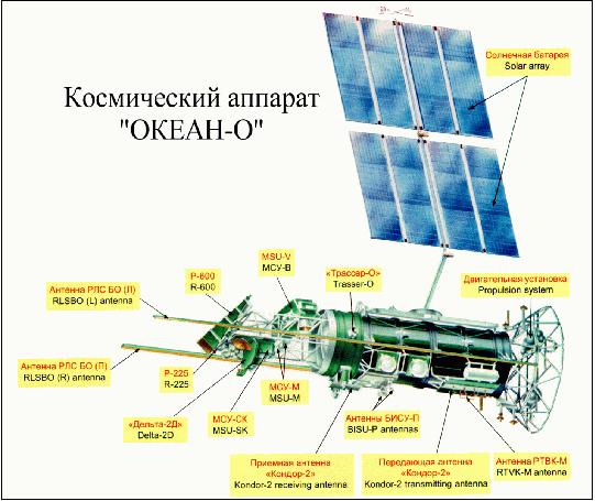
The Okean-O series, a joint Ukrainian/Russian remote sensing program, represents a new generation spacecraft over the Okean-O1 series with regard to the sensor complement (the S/C is also considerably larger). The Okean-O-1 spacecraft/mission was sponsored by NKAU (National Space Agency of Ukraine) and to some extent by RKA (Russian Space Agency), designed by the Yangel Yuzhnoye State Design Office, and built by NPO Yuzhny Machine-Building Plant Production Association (Yuzhmash), Dnepropetrovsk, Ukraine. All the scientific assets of the spacecraft, scientific data downloaded from each instrument are mutually divided between Russia and Ukraine on an equal basis.
Spacecraft
The satellite is three-axis stabilized with an attitude pointing accuracy of ±10 arcmin and an angular stabilization velocity of ±0.0015º/s. Solar power of up to 3.5 kW is provided. The spacecraft mass is 6150 kg, the mass of the onboard special complex (BSC) is 1520 kg. The spacecraft bus, a cylinder, has a diameter of 1.9 m and a length of 6.6 m. The S/C design life is three years. Note: The Okean-O-1 spacecraft is also being referred to as Sich-2. 1) 2) 3)
S/C communication
1) BISU-P (Onboard Information System Unified). This is a digital system with an X-band downlink, the frequency is 8.2 GHz. The transmission rate is 61.44 Mbit/s (4R) or 15.36 Mbit/s. The onboard date recorder has recording rates of 15.36 Mbit/s or 0.96 Mbit/s.
2) RTVK-M (Radio and Television Complex). This is an analog system in VHF-band with a downlink frequency of 137.4 MHz and a bandwidth of 2.4 kHz.
3) BITS-2-7 (Onboard Information and Telemetry System). This is a digital system in the UHF-band with a downlink frequency of 600 MHz.
Holders of the scientific data in Russia are:
• NITs Planeta (Moscow)
• ZS RTsPOD (Novosibirsk)
• DV RTsPOD (Khabarovsk)
Holders of the scientific data in the Ukraine are:
• Data Reception Center of the National Space Agency, GNPP Obriy (Snoviyanka, Chernigov region)
• TsORD, GNPTs Priroda (Vyshgorod, Kiev region).
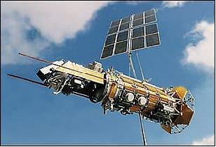
Figure 2: Alternate view of the Okean-O-1 spacecraft (image credit: NKAU)
Launch
Okean-O-1 was launched on a Zenit-2 vehicle from the Baikonur Cosmodrome, Kazakhstan, on July 17, 1999.
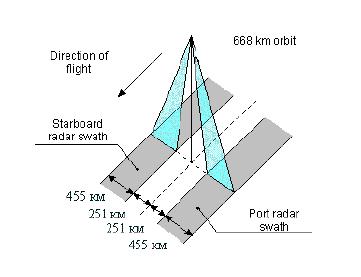
Orbit: Sun-synchronous near-circular orbit, mean altitude = 668 km, inclination = 98º, the revisit time is between 4 to 16 days.
Mission Status
Okean-O-1 stopped all operations in the fall of 2000 (after a year of operations) due to attitude control problems of the spacecraft. At the time, both space agencies, NKAU and RKA (Russian Space Agency or Rosaviakosmos), did not provide any funding for the development of a further Okean-O spacecraft due to the tight economic situation in the Ukraine and in Russia.
Sensor Complement
The payload instruments are part of BSC (Onboard Special Complex). 4) 5)
MSU-V (High-Resolution Multispectral Scanner)
MSU-V (Kazan) with photodiode detectors. The instrument has an observation swath width of 195 km.
Band Nr. | Spectral Range | Spatial resolution |
Band 1 | 0.45 - 0.52 µm (VIS) | 50 m |
Band 2 | 0.54 - 0.61 µm (VIS) | 50 m |
Band 3 | 0.63 - 0.73 µm (VIS) | 50 m |
Band 4 | 0.78 - 0.92 µm (VIS) | 50 m |
Band 5 | 0.91 - 0.997 µm (NIR) | 50 m |
Band 6 | 1.47 - 1.62 µm (SWIR) | 100 m |
Band 7 | 2.06 - 2.38 µm (SWIR) | 300 m |
Band 8 | 10.6 - 12.0 µm (TIR) | 250 m |
MSU-SK (Multispectral Scanner of Moderate Resolution)
MSU-SK comes with conical scanning (ISDE, Moscow). Swath width = 620 km for each instrument; there are 5 spectral bands: 0.53 - 0.59 µm, 0.59 - 0.72 µm, 0.72 - 0.81 µm, 0.81 - 1.1 µm, 10.4 - 12.6 µm (TIR). Spatial resolution = 157 m x 245 m (across-track and along-track) in VNIR and 590 m x 820 m in TIR. There are two units onboard: MSU-SK1 is a forward-looking instrument, while MSU-SK2 is an aft-looking instrument - the off-nadir angle for each instrument is 39º.
MSU-M (Multispectral Opto-Mechanical Scanner)
MSU-M is a low-resolution instrument developed at ISDE, Moscow. Resolution = 1.5 km x 1.8 km, swath = 2000 km. Objective: cloud monitoring and sea surface temperature. Spectral ranges: 0.5 - 0.6 µm; 0.6 - 0.7 µm; 0.7 - 0.8 µm; 0.8 - 1.1 µm. There are two units - prime and spare.
RTVK-M (Radio and TV Complex)
RTVK-M is part of MSU-M developed at ISDE, Moscow. The MSU-M and RLSBO instruments are integrated into one complex. Data from RLSBO (Right or Left) and MSU-M (1 among 4 channels) may be selected. Their information may be transmitted via a VHF (137.4 MHz) downlink to users in real-time. There are over 1000 VHF receiving stations in the ground segment.
RLSBO (Side Looking Real Aperture Radar)
The instrumment has a wavelength of 30 mm (X-band). Resolution: 1.3 km cross-track and 2.5 km along-track. The swath width is 455 km for each instrument. There are two instruments onboard, one looking to either side of the ground track. The near angle of incidence is ±20º. Both instruments operate in parallel.
Delta-2D (Scanning Microwave Radiometer)
The instrument features conical scanning (SRB/MPEI, Moscow). Objective: Measurement of sea surface temperatures (SST) and monitoring of Earth surface temperatures, characteristics of arctic ice, etc. The instrument is an improved version of IKAR-P heritage flown on Priroda, providing four frequency bands. The swath width of Delta-2D is 1130 km, there are two polarizations, the off-nadir angle is 40º.
Frequency (GHz) | Wavelength (mm) | Polarization | Resolution | Noise temp. measurement error |
37.5 | 8 | V, H | 17 km x 21 km | 0.15 K |
22.3 | 13.5 | V, H | 28 km x 37 km | 0.15 K |
13.0 | 22 | V, H | 49 km x 65 km | 0.1 K |
6.9 | 45 | V, H | 91 km x 120 km | 0.1 K |
R-600 (Passive Microwave Radiometer)
R-600 was built by MPEI, Moscow. Objective: measurement of emissive microwave radiation at the atmosphere/sea surface interface. Wavelength (frequency) = 60 mm (5 GHz); The footprint of the instrument is about 165 km in diameter. There are two polarizations, the off-nadir angle is 42º.
R-225 (Passive Microwave Radiometer)
R-225 was built by MPEI, Moscow. Wavelength (frequency) = 22.5 mm (13.3 GHz); The footprint of the instrument is about 130 km in diameter. There are two polarizations, the off-nadir angle is 42º.
Trasser-O (Polarization Spectroradiometer-Okean)
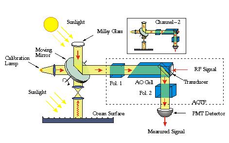
Trasser -O was designed and built by STCUI-RAS (Scientific Technological Center of Unique Instruments - Russian Academy of Sciences), Moscow. A non-scanning demonstration device with an off-nadir angle of 20º. Trasser introduces the technology of AOTF (Acousto-Optic Tunable Filters) in acousto-optic spectrometers (AOS). The measurement concept is based on collinear diffraction of light by ultrasonic waves propagating in an anisotropic crystal (optical radiation diffraction on bulk phase grating being generated in the quartz crystal). The AOTF technique offers a means of high-accuracy spectral monitoring in the spectral region from about 250 nm (UV) to about 4.4 µm (MWIR). The relatively new AOTF technique of optical spectra detection (by absorption, emission or scattering of light) may be employed for a number of applications such as: monitoring of atmospheric trace gases, of sea surface characteristics (bioproductivity of ocean surfaces, detection of polluted ocean surfaces), and of vegetable canopies on land. 6) 7)
Background: The first spaceborne AOS instrument by the name of Trasser was flown on Okean-O1-N3 with a launch on July 5, 1988. The instrument was operational until 1990. In parallel to Trasser, there was an airborne AOS instrument by the name of POLAS-128(Polarization-sensitive Acousto-optic Spectrometer) which was also used for underflights of Trasser. Both instruments operated in the visible band. They were developed and built by VNIIFTRI (All-Russian Scientific Research Institute of Physical and Radio-Engineering Measurements). Later on (1996) the Trasser work was continued at STCUI-RAS.
Spectral range | 430 - 800 nm |
Polarization channels | 2 (H and V) |
Spectral channels | 62 x 2 (for each polarization channel) |
Bandwidth | From 3 nm at 430 nm to 12 nm at 800 nm |
Detection range on radiance spectral density | 13-26 µW/ (mm2 x nm x sr) |
Sampling time | 3.3 s per spectrum |
Input angle | 2º (corresponding to a spatial resolution of 45 km at spacecraft altitude of 668 km) |
Off-nadir angle | 20º |
Detector type | PMT (Photomultiplier Tube) |
Data quantization | 12 bit |
Sample rate | 2 Hz |
Size of optical head | 300 mm diameter x 702 mm |
Data rate | 14 kbit/channel |
Mass of instrument unit | 15 kg optical head, 16.5 kg signal processing unit, 5 kg control unit, 9 kg power supply commutator |
Instrument mass, power | 30 kg, 285 W |
Trasser-O consists of the following elements (see Figure 5):
• A double-channel (H,V) spectrometer
• A calibration system consisting of an internal gray lamb and a sun view through a milky glass
• A three-position movable mirror
• AOTF (Acousto-Optic Tunable Filter - virtually a tunable monochromator) consisting of two polarizers (H, V) and an acousto-optic cell. An external RF reference signal is introduced via a piezotransducer for elasto-optic crystal excitation.
AOTF principle: AOTF is a spectral element containing an elasto-optic crystal with piezotransducer attached and two polarizers. It allows selecting radiation in the narrow spectral band with the wavelength controlled by the frequency of ultrasound supplied to the crystal. In AOTF, an anisotropic diffraction of the light beam takes place at phase volume grating caused by a running acoustic wave. Two features of this physical effect are critical for the selection. The first one is the resonance nature of acousto-optic interaction: the synchronism wavelength of light is tuned by acoustic frequency. The second feature is changing the polarization and direction of diffracted wave that permits to separate it by polarizers or diaphragms.
The current non-scanning design of Trasser instruments offers a rather limited observation coverage, a footprint of about 25 km in diameter which progresses in the along-track direction as the spacecraft moves in its ground track. This renders a coverage scheme very similar in scope to altimetric measurements. However, the overall goal of Trasser-type instruments is to provide eventually an alternate measurement approach to conventional hyperspectral imaging systems, namely AOS imagers. For Trasser, this requires the addition of an optical front-end to the current instrument configuration, permitting a spatial cross-track scan to obtain spatial/spectral image cubes.

Kondor-2
Kondor-2 is an onboard data collection system. The objective is to provide collection services for the Kondor-1 DCPs (Data Collection Platform) at 1533 MHz as well as to Kondor-3 receiving stations at 460 MHz. The data receiving rate of Kondor-2 is 500 bit/s, the transmission rate is 2 kbit/s. Kondor-2 has an onboard storage capacity of 64 kbit. - The positioning accuracy of Kondor-1 DCPs is about 3.5 km x 2.5 km in polar regions, and about 3.5 km x 20 km in the other regions.
References
1) Okean-O Earth Observation Spacecraft, a brochure of RKA and NKAU provided by B. Kutuza of IRE, Moscow
2) https://web.archive.org/web/20090127052612/http://eng.ntsomz.ru:80/spacecraft/okean_o
3) http://www.nkau.gov.ua/nsau/catalogNEW.nsf/0/9EAAC86874B6D192C3256BF8004C1238?OpenDocument&Lang=E
4) Information provided by B. Kutuza of IRE, Moscow, and translated by B. Zhukov of DLR, Oberpfaffenhofen
5) I. V. Bragin, V. P. Sgibnew, K. A. Pobedonostsev, A. V. Evtushenko, et. al., “Space-Based Remote Sensing Complexes,” Proceedings of the 29th European Microwave Conference, Munich, Sept. 1999, pp. 388-390
6) Information provided by V. I. Pustovoit, V. E. Pozhar, and V. N. Zhogun of STCUI-RAS
7) V. I. Pustovoit, V. E. Pozhar, “Acousto-optical spectrometers for Earth remote sensing,” Proceedings of SPIE 44th Annual Meeting, International Symposium on Optical Science, Engineering, and Instrumentation, Denver, CO, July 18-23, 1999
The information compiled and edited in this article was provided by Herbert J. Kramer from his documentation of: ”Observation of the Earth and Its Environment: Survey of Missions and Sensors” (Springer Verlag) as well as many other sources after the publication of the 4th edition in 2002. - Comments and corrections to this article are always welcome for further updates (eoportal@symbios.space).