PISat (PESIT Imaging Satellite)
EO
Ocean
Multi-purpose imagery (ocean)
Land
Quick facts
Overview
| Mission type | EO |
| Agency | PES Institute of Technology |
| Mission status | Operational (nominal) |
| Launch date | 26 Sep 2016 |
| Measurement domain | Ocean, Land |
| Measurement category | Multi-purpose imagery (ocean), Multi-purpose imagery (land) |
| CEOS EO Handbook | See PISat (PESIT Imaging Satellite) summary |
PISat (PESIT Imaging Satellite)
Overview Spacecraft Launch Sensor Complement References
Overview
PISat is a low cost nanosatellite, designed and developed at the Crucible of Research and Innovation Laboratory of PESIT (PES Institute of Technology), Bangalore, India. The PISat project actually consists of a consortium of Indian colleges, with the support of ISRO (Indian Space Research Organization) and IE (Institution of Engineers) of India, to provide a hands-on environment for students in all aspects of satellite building and operations.1) 2)
Spacecraft
PISat is a nanosatellite of size 254 x 256 x 181 mm and a mass of 5.3 kg. The spacecraft is equipped with an imaging instrument to capture imagery of Earth's surface.
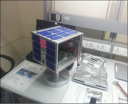
ADCS (Attitude Determination and Control Subsystem): PISAT is a three axis stabilized satellite with active magnetic control system. The attitude sensors onboard are tri-axial MEMS based IMU (Inertial Measurement Unit) and FPSS (Four Pi steradian Sun Sensors). The IMU used onboard is ADIS16405 (Figure 3) from Analog Devices Inc. that includes a tri-axial gyroscope, accelerometer, and magnetometer. The tri -axial magnetometer maximum range is about ±3,50,000 nT, initial sensitivity of 50 nT and initial bias error of ±400 nT. The factory calibration characterizes each sensor for sensitivity, bias, alignment, and linear acceleration.
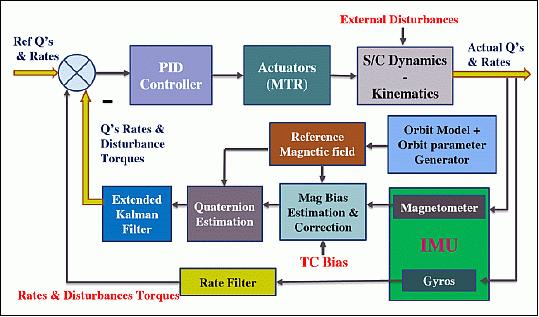
The ADCS includes MTRs (Magnetic Torque Rods) as actuators; they produce magnetic dipole moments, which interact with the Earth’s magnetic field to generate torques on the satellite. PISAT is aiming at a pointing accuracy of 5º, hence active magnetic control is adequate to satisfy the mission requirement.
The PISAT ADCS operating modes include suspended mode, detumbling mode, three axis magnetic control mode and safe mode.
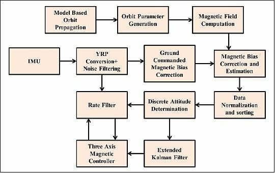
The orbit model provides the state vectors (position and velocity) in ECI (Earth Centered Inertial) and ECF (Earth Centered Fixed) reference frames. For the onboard attitude determination using magnetometer data, it is necessary to compute orbital parameters viz. declination, longitude, argument of perigee, true anomaly, inclination, in order to calculate the reference field vector components in orbit frame.
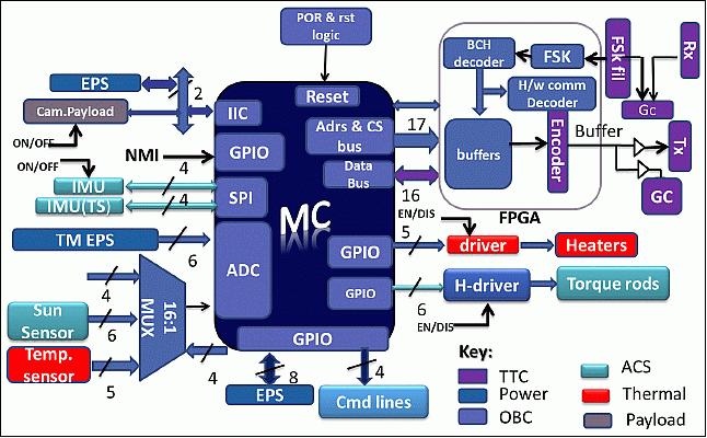
OBC (On Board Computer): The OBC consists of an Atmel 32 bit microcontroller AVR32- AT32UC3A0512 (MC) with built in Flash PROM, RAM, ADC, PWMs and timers, with the clock speed of 12 MHz. The primary role of the PISAT OBC is to control all subsystems of the satellite. The most important tasks performed by the PISAT OBC are:
• Receive and respond to commands from the ground station as well as to handle the general housekeeping of the satellite.
• Collect the telemetry data, format and encode the data for transmitting to the ground station.
• Onboard attitude determination by monitoring Earth’s magnetic field and control operations using control algorithms.
• Store payload data and playback telemetry data during non-visible period for transmission to ground during visibility.
Interface between NanoCam and OBC:
- Nanocam runs on free RTOS and supports FTP for data transfer.
- OBC runs on custom RTE (Real Time Executive) developed by students at PESIT.
- Providing support for FTP on OBC is non trivial.
- GomSpace provided a new firmware on Nanocam that allows access to memory on Nanocam using the CSP (CubeSat Space Protocol).
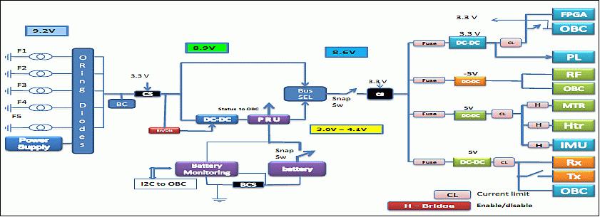
EPS (Electrical Power Subsystem): EPS is responsible for the generation, conditioning and distribution of power within the satellite. The EPS manages the power input from solar cells, charging of onboard batteries, distributes electrical power, at the required voltages, to all other subsystem elements of the satellite. The basic architecture of PISAT power system is depicted in Figure 4.
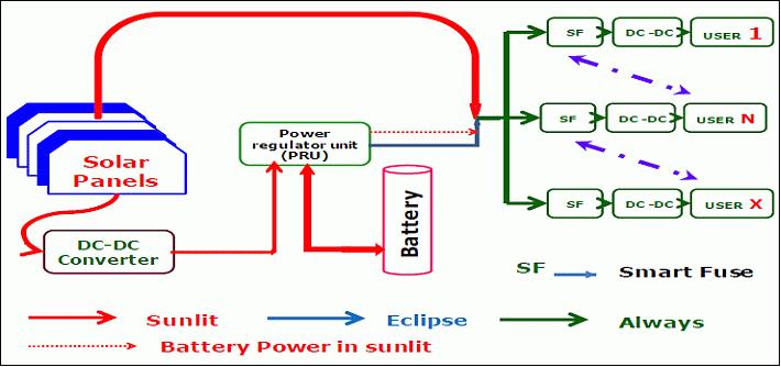
The EPS uses a distributed single bus architecture. It features a total of 52 EMCORE ATJ (Advanced Triple Junction) solar cells which are bonded on 5 faces of the spacecraft panels forming 13 strings. A string length of 4 cells is maintained for all the 13 strings.
Solar array raw bus voltage | 8.8 V |
Max SA current | 1.5 A |
Max power generation | 13 W |
Battery capacity | 5.2 Ahr |
Nominal battery discharge voltage | 3.7 V |
DC outputs | +5 V, 3.3 V, -5 V ± 0.1 V |
Continuous power requirement | 4.5 W (S), 3.5 W(E) |
Max battery DoD | 15% |
Power margin | 2.5 W |
RF communications: The RF system of PISAT facilitates command reception and telemetry data transmission. The onboard RF system comprises of one non-coherent receiver, one transmitter and the associated antenna system. Use of S-band data transmission: the uplink frequency is 2030 MHz, the downlink frequency is 2240 MHz. The modulation scheme employs FSK/FM in the uplink with a data rate of 100 bit/s and BPSK modulation in the downlink with a coded transmission rate of 20 kbit/s (actual data rate is 10 kbit/s). 3)
Launch
A launch of the PISat nanosatellite as a secondary payload is planned for 2015 on a PSLV launcher of ISRO. A launch arrangement was signed in August 2014.
PISat's launch was delayed; the nanosatellite launched on 26 September 2016.
Orbit: Sun-synchronous near circular orbit, altitude = 630 km, inclination = 97.86º.
Sensor Complement
With regard to the payload, PISat is a cooperative project with GomSpace of Aalborg, Denmark.
NanoCam
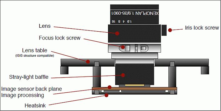
NanoCam is a CMOS color camera for Earth observation experimentation manufactured by GomSpace of Aalborg, Denmark. NanoCam is a flexible and modular system to rapidly implement tailored imaging systems based on costumer requirements. The “NanoCam C1U” is an off-the shelf configuration of the NanoCam system, consisting of: Lens, lens table, image acquisition board, image processing board and software. 4)
NanoCam C1U has been designed to be implementable in an ISIS 1U cubesat structure together with GomSpace’s onboard computers, attitude control system, radio transceiver and power products to allow low cost Earth observation using cubesats.
The C1U is based in an industrial ruggedized lens from Schneider Optics. The lens mounts in the lens table, which is the main load bearing part of the system. The image sensor is located at the top side of the camera printed circuit board beneath the lens table and interfaces to the image processor and memory components on the back side of the board.
NanoCam has a 3MP 10 bit color CMOS based detector and acquires the image at a resolution of 2048 H x 1536 V pixel. This covers about 165 km x 125 km for a spatial resolution of 80 m. The imaging CMOS detector, with a frame rate of 12 frame/s, gives a total capture time of 83.3 ms.
The Nanocam uses the CSP enabled I2C serial communication protocol in multi-master mode to communicate with the OBC for command and data transfer. The NanoCam processor has the following specifications:
- 210 MIPS processor
- 32 MB on board RAM
- 2 GB solid state storage
- JPEG compression.
The communication interface between the OBC and the payload is via I2C (Inter-Integrated Circuits) which is a serial communication protocol. It supports communication between multiple devices connected to the same bus of two lines (data and clock) and data transmission speeds up to 400 kbit/s. All commands and their responses are sent using this interface.
The main connector to the satellite bus is a high grade 15 pin Bi-Lobe from Omnetics P/N A29100-015. The connector mates with P/N A28000-15 (included with NanoCam). In addition, there is a Molex PicoBlade 12 pin connector for JTAG (Joint Test Action Group) access and debugging used to upload new firmware and accessing the debugging serial port without using the main flight connector. Pins 1-8 are pin-to-pin compatible with the JTAG port on all other GomSpace products (from mid 2011-), and pins 9-12 are compatible with the debugging connector on all GomSpace products. The two functions are brought together in one connector on NanoCam due to its limited size.
The NanoCam device has a total mass of 166 gram.

References
1) Dhananjay V. Kumar, Adarsh R., Mahendra M. Nayak, V. K. Agrawal, Dayanand B. M., “Test System for Payload-OBC interface in PiSat,” Proceedings of iCubeSat 2014, 3rd Interplanetary CubeSat Workshop, Pasadena, CA, USA, May 27-28, 2014, URL of paper: https://icubesat.files.wordpress.com/2014/05/icubesat-org_2014_b-3-1-test_kumar_201405241651_paper.pdf URL of presentation: https://icubesat.files.wordpress.com/2014/05/icubesat-org_2014_b-3-1-test_kumar_201405241651.pdf
2) Shashank Nagesh Bhat, Arjun Haritsa Krishnamurthy, Divya Rao, M. Mahendra Nayak, V.K. Agrawal, “Implementation of three axis magnetic control mode for PISAT,” Proceedings of iCubeSat 2014, 3rd Interplanetary CubeSat Workshop, Pasadena, CA, USA, May 27-28, 2014, URL: https://icubesat.files.wordpress.com/2014/05/icubesat-org_2014_b-3-3-3axis_bhat_201405261641_paper.pdf
3) Information provided by Prof. Divya Rao of PESIT (PES Institute of Technology), Bangalore, India.
4) “NanoCam C1U Datasheet,” GOMSpace, URL: http://nativesat.com/wp-content/uploads/2014/07/NANOCAM-6.1.pdf
The information compiled and edited in this article was provided by Herbert J. Kramer from his documentation of: ”Observation of the Earth and Its Environment: Survey of Missions and Sensors” (Springer Verlag) as well as many other sources after the publication of the 4th edition in 2002. - Comments and corrections to this article are always welcome for further updates (eoportal@symbios.space).
Overview Spacecraft Launch Sensor Complement References Back to Top