PROBA-V (Project for On-Board Autonomy - Vegetation) and Companion CubeSat
EO
ESA
Ocean
Multi-purpose imagery (ocean)
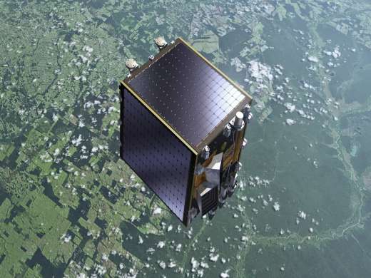
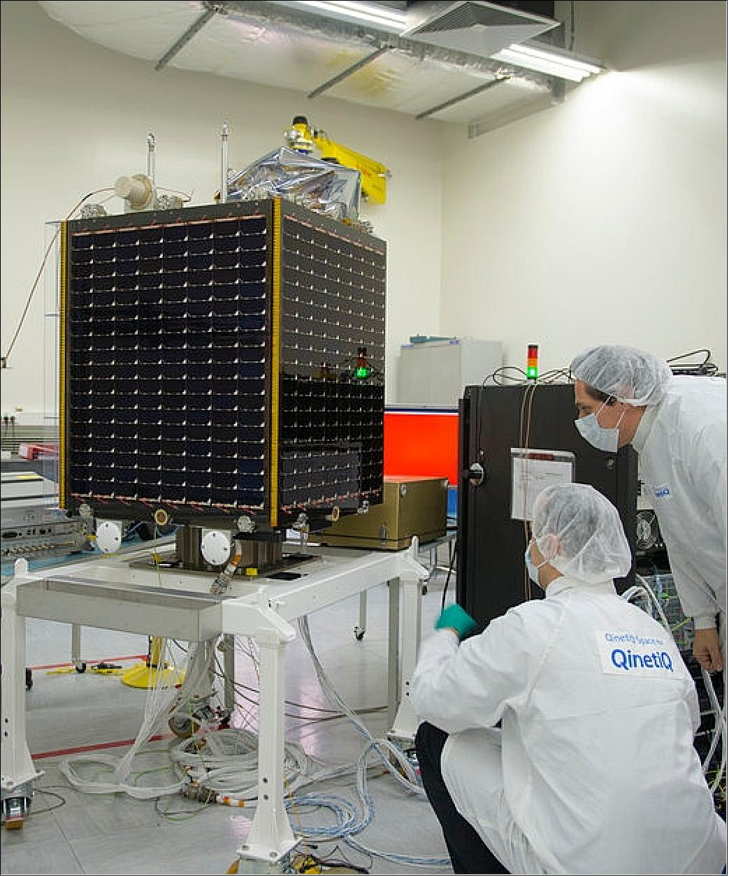
Launched in May 2013, PROBA-V (Project for On-Board Autonomy - Vegetation) was a satellite imaging mission of the European Space Agency’s (ESA) PROBA series. The project was initiated by the Department of Belgian Science Policy Office (BELSPO), and QinetiQ Space was commissioned to construct the satellite. PROBA-V recorded images of the Earth in order to track general land use, link vegetation behaviour to meteorological events and aid disaster management, and was decommissioned in October 2021.
In October 2023, Aerospacelab launched PVCC (Proba-V Companion Cubesat), a cut-down version of the vegetation-monitoring instrument, aboard the Earth-observing Proba-V satellite, to perform experimental combined observations with its predecessor. 123)
Quick facts
Overview
| Mission type | EO |
| Agency | ESA, BELSPO |
| Mission status | Mission complete |
| Launch date | 07 May 2013 |
| End of life date | 31 Oct 2021 |
| Measurement domain | Ocean, Land |
| Measurement category | Multi-purpose imagery (ocean), Multi-purpose imagery (land), Vegetation, Albedo and reflectance |
| Measurement detailed | Ocean imagery and water leaving spectral radiance, Land surface imagery, Vegetation type, Earth surface albedo, Leaf Area Index (LAI), Land cover, Normalized Differential Vegetation Index (NDVI), Photosynthetically Active Radiation (PAR), Fraction of Absorbed PAR (FAPAR) |
| Instruments | Vegetation |
| Instrument type | Imaging multi-spectral radiometers (vis/IR) |
| CEOS EO Handbook | See PROBA-V (Project for On-Board Autonomy - Vegetation) and Companion CubeSat summary |
Related Resources
Summary
Mission Capabilities
The primary payload was the Vegetation Instrument, a multi-spectral radiometer, built by Belgian satellite specialists, Optronic Instruments & Products (OIP) systems. PROBA-V’s Field of View (FOV) is constructed from three Spectral Imagers (SI). Each SI contained one three-mirror anastigmat (TMA) telescope, and a beam splitter to divide up separate visible, near-infrared (VNIR) and short-wave infrared (SWIR) spectral bands.
Alongside each telescope, the optical bench also carried star tracker optical heads allowing for precise co-alignment, and a radiator to remove excess heat from the optical system.
Performance Specifications
Each TMA was a multispectral pushbroom spectrometer, observing the surface with a swath width of 2250 km, a noticeably large value for a satellite of PROBA-V’s size. Accounting for cloud cover, this corresponded to a full sweep of Earth’s vegetation every 10 days. Each telescope had an individual spatial resolution of 300 m, yielding a 100 m resolution across the central telescope. PROBA-V measured across four spectral bands: blue, red, VNIR (visible near infrared), and SWIR (shortwave infrared).
PROBA-V operated in a sun-synchronous orbit with an altitude of 820 km, which decayed over time due to the lack of any on-board thrusters. It had an orbital period of 101 minutes and an inclination of 98.64°.
Space and Hardware Components
The satellite bus was built on the heritage of the PROBA-1 and PROBA-2 missions, with only the on-board switching (OBS) receiving minor modifications. An S-band Telemetry, Tracking and Command (TT&C) mode is used in conjunction with an X-band data downlink subsystem. A number of demonstration modules were also included on PROBA-V. These included the Energetic Particle Telescope (PET), a new radiation monitoring sensor, and HERMOD (High Density Space Form Connector Demonstration), testing multi-line optical fibre reliability in space.
In July 2020, due to an error on board, one of the three telescopes began observing the Earth at night, and so the mission objective was altered. PROBA-V began making test observations of Europe and Aftica, assisting with drought warnings in the African Sahel.
PROBA-V (Project for On-Board Autonomy - Vegetation) and Companion CubeSat
Overview Spacecraft Launch Mission Status Sensor Complement Payloads Ground Segment
References
Overview
The PROBA-V (Vegetation) mission definition is an attempt, spearheaded by ESA and CNES, to accommodate an improved smaller version of the large VGT (Vegetation) optical instrument of SPOT-4 and SPOT-5 mission heritage on a small satellite bus, such as the one of PROBA-2.
As of 2008, small satellite technologies have reached a level of maturity and reliability to be used as a platform for an operational Earth observation mission. Furthermore, advancements in the techniques of detectors, optics fabrication and metrology are considered sufficiently mature to permit the design of a compact multispectral optical instrument. 1) 2) 3) 4) 5) 6) 7) 8) 9) 10) 11) 12) 13) 14) 15) 16)
The C/D Phase started in July 2010. The system CDR (Critical Design Review) took place in the spring of 2011. The project is currently (summer 2012) in its Phase D, with a Final Acceptance Review planned for December 2012. ESA is responsible for the overall mission, the technological payloads and for the launcher selection.
Background: The VGT instruments (VGT1 & VGT2), each with a mass of ~140 kg and fairly large size, have provided the user community with almost daily global observations of continental surfaces at a resolution of 1.15 km on a swath of ~2200 km. The instruments VGT1 on SPOT-4 (launch March 24, 1998) and VGT2 on SPOT-5 (launch May 4, 2002) are quasi similar optical instruments operating in the VNIR (3 bands) and SWIR (1 band) range.
The Vegetation instruments were jointly developed and funded by France, Belgium, Italy, Sweden, and the EC (European Commission). The consortium of CNES, BelSPO (Federal Public Planning Service Science Policy), SNSB (Swedish National Space Board) and VITO (Flemish Institute for Technological Research) is providing the user segment services (data processing, archiving, distribution). Vegetation principally addresses key observations in the following application domains:
• General land use in relation to vegetation cover and its changes
• Vegetation behavior to strong meteorological events (severe droughts) and climate changes (long-term behavior of the vegetation cover)
• Disaster management (detection of fires and surface water bodies)
• Biophysical parameters for model input devoted to water budgets and primary productivity (agriculture, ecosystem vulnerability, etc.).
As of 2008, a Vegetation archive of 10 years of consistent global data sets has been established permitting researchers access on a long-term basis. The SPOT-5 operational lifetime is estimated to expire in 2012. Pleiades, the next French satellite for Earth Observation, is solely dedicated to high-resolution imaging (on a fairly narrow swath) and will not embark any instrument providing vegetation data.
Since the SPOT series spacecraft will not be continued and the SPOT-5 spacecraft will eventually fail — there is of course a great interest in the EO user community to the Vegetation observation in the context of a smaller mission, affordable to all concerned. 17)
PROBA-V will continue the production of Vegetation products exploiting advanced small satellite technology. However, this implies in particular a redesign of the Vegetation payload into a much smaller unit to be able to accommodate it onto the PROBA bus.
Overview of key requirements of the PROBA-V mission - and some improvements compared to SPOT/Vegetation:
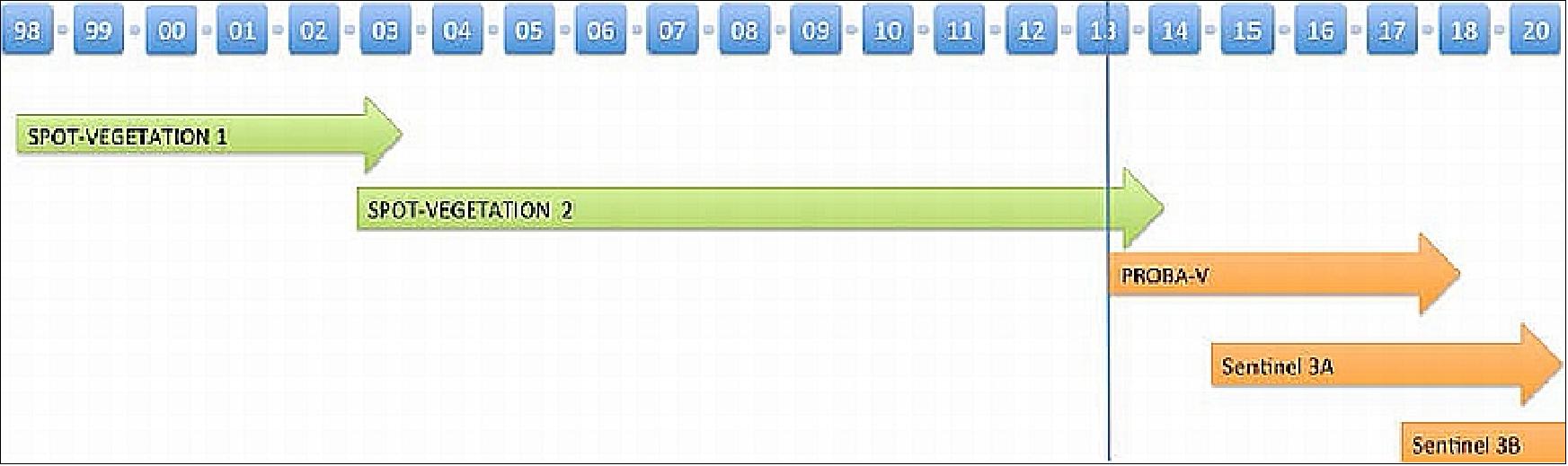
- Data and service continuity: filling the gap between SPOT-VGT and the Sentinel-3 mission
- Spectral and radiometric performance identical to VGT
- GSD: 1 km mandatory, improved GSD is highly disirable: 300 m (VNIR bands), 600 m (SWIR band). Image quality and geometric accuracy, equal to or better than SPOT-VGT
- Provision of daily global coverage of the land masses in the latitudes 35º and 75º North and in the latitudes between 35° and 56° South, with a 90% daily coverage of equatorial zones - and 100% two-daily imaging, during day time, of the land masses in the latitudes between 35º North and 35º South..
An extensive feasibility study and trade-off work was undertaken to identify a solution that could meet not only the technical challenges, but that could also be developed and tested within a tight budget of a small satellite mission. 19) 20)
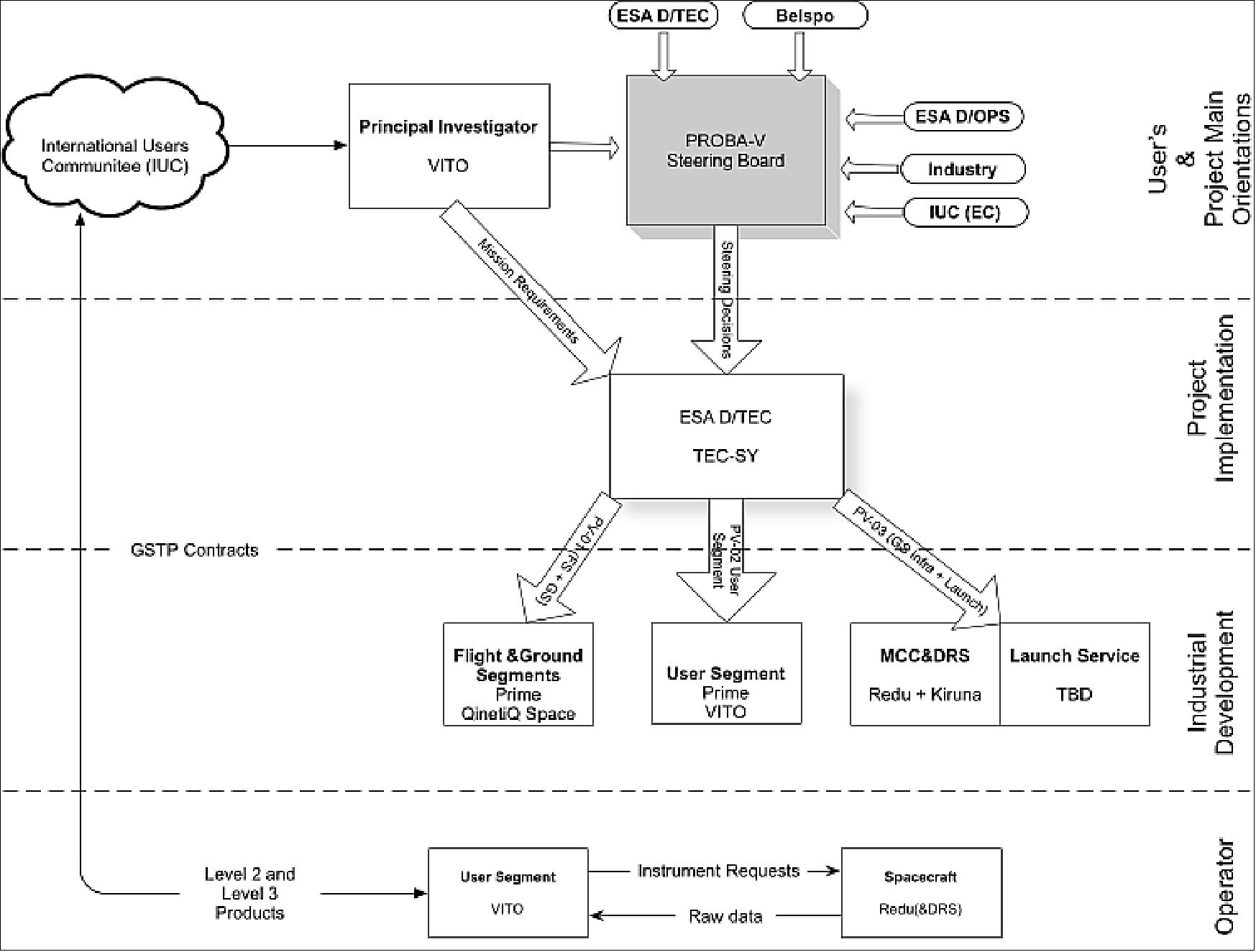
The PROBA-V project of ESA includes the Space Segment (platform contract award to QinetiQ Space NV of Kruibeke, Belgium - formerly Verhaert), the Mission Control Center (Redu, Belgium) and the User Segment (data processing facility) at VITO NV. VITO (Vlaamse instelling voor technologisch onderzoek - Flemish Institute for Technological Research) is located in northern Belgium. VITO's processing center of VGT1 and 2 data (SPOT-4 and SPOT-5) is operational since 1999. VITO is also the prime investigator and data service provider of PROBA-V for the user community including product quality control. 21)
Implementation schedule:
• The Phase B of the project started in January 2009
• SRR (System Requirements Review) is in Q4 of 2009
• PDR (Preliminary Design Review) in Q2 of 2010
• HMA (Heterogeneous Mission Access) and QA4EO (Quality Assurance for Earth Observation) implementation for user data. Planned interoperability with GSCDA V2 (GMES Space Component Data Access Version 2).
Spacecraft
An industrial team, led by QinetiQ Space NV (Belgium), is supported by several European subcontractors and suppliers, and is responsible for the development of the flight satellite platform, the vegetation payload and the Ground Segment.
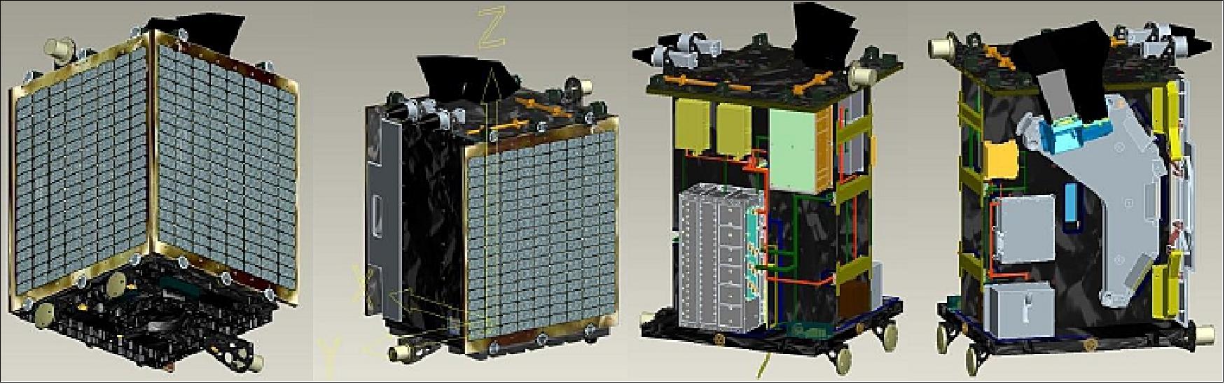
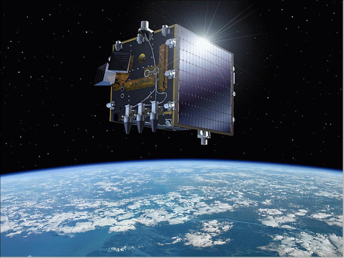
The spacecraft bus (fully redundant) is of heritage from the PROBA-1 and PROBA-2 missions (structure, avionics, AOCS, OBS with minor modifications). The PROBA-V spacecraft has a total mass of 138 kg, and a volume of 80 cm x 80 cm x 100 cm. The three-axis stabilized platform is designed for a nominal mission lifetime of 2.5 years (Ref. 7). 22) 23) 24) 25)
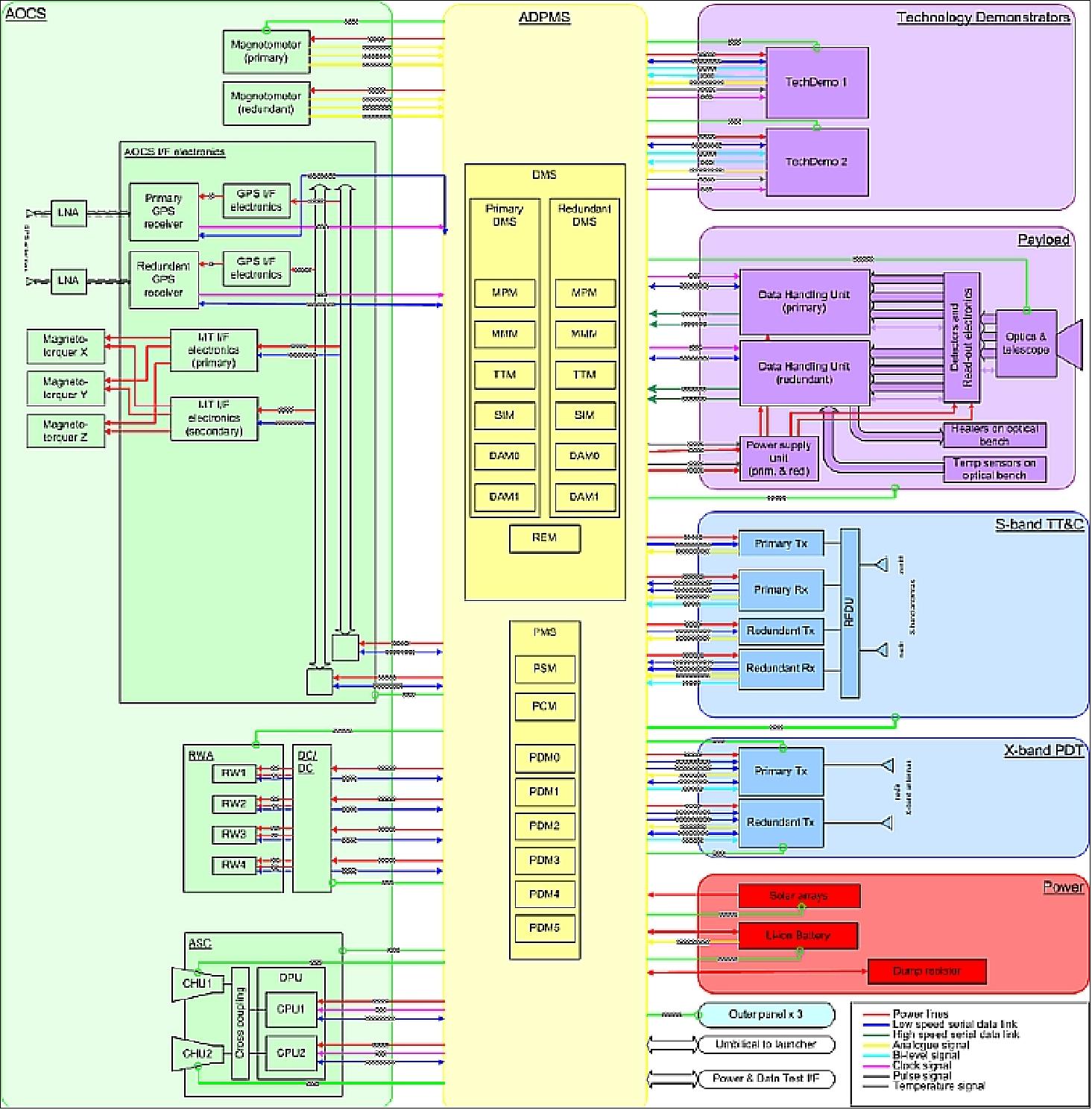
The spacecraft resources management is built around ADPMS (Advanced Data and Power Management System), which is currently flying on PROBA-2. The data handling part of ADPMS is partitioned using compact PCI modules. A cold redundant mass memory module of 16 Gbit is foreseen for PROBA-V. The newly developed mass memory will use NAND flash technology.
The avionics architecture can be divided in several sections:
• The AOCS block, containing all AOCS equipment and the required additional electronics in order to adapt or convert interfaces and supply voltages.
• The ADPMS, featuring the two redundant data handling lanes and its power section. It is the center of all data handling, communications and power conditioning and distribution.
• The main payload (Vegetation Instrument).
• The technology demonstrators. Four technology demonstrator payloads have been incorporated in the design.
• The communication section, featuring full redundancy for all modules. It comprises the S-band TT&C subsystem and the X-band data downlink subsystem.
• The power distribution and conditioning part of ADPMS supplies an unregulated bus, with each equipment having its internal DC/DC converter. The power conditioning system is designed around a Li-ion battery and a dump resistor ((to dissipate excess current).
The different subsystems of the PROBA-V satellite are summarized in Table 1. The electrical architecture of PROBA-V, built around the ADPMS, is shown in Figure 4.
The data handling part of ADPMS is built up from several modules, each based on the compact PCI standard. The ADPMS design is fully redundant. The PROBA-V configuration of ADPMS comprises:
• MPM (Main Processor Module), based on a LEON2 processor (ASIC), providing the processing power, memory and physical interfaces to control all other peripheral boards
• TTM (Telecommand and Telemetry Module), providing the bidirectional interface between the spacecraft and the ground stations
• SIM (Spacecraft Interface Module), providing the bidirectional communication interfaces between the ADPMS and the other spacecraft units
• DAM (Data Acquisition Module), providing the data acquisition of analog, digital and temperature signals
• MMM (Mass Memory Module), providing a data storage capability of 16 GByte EDAC protected and based on NAND flash technology
• REM (Reconfiguration and Emergency Module (REM), providing hardware functions to allow an easy reconfiguration and recovery of ADPMS directly from ground in case of problems.
The Power Management System of ADPMS supplies a battery-regulated bus, designed around a Li-ion battery. The power management system is built-up from the following modules:
• PCM (Power Conditioning Module), managing and regulating the incoming and outgoing power
• PDM (Power Distribution Module), managing the power distribution and over current protections.
The power management system can manage a total power of 300 W. Each power output line can handle a current of 2 A.
Subsystem | Equipment | Heritage |
Avionics | - ADPMS (cold redundant) | PROBA-2 |
EPS (Electric Power Subsystem) | - Photo-Voltaic Array : Triple junction GaAs cells (3G-28%) | Herschel |
Bus structure | - Aluminum (AA2024-T3): Face sheets t = 0.8 mm inner panels, t = 0.4 mm top and nadir panel), honeycomb core (t = 10. 8 mm) | New development |
AOCS actuators | 3 magnetotorquers (internally cold redundant of ZARM, Germany) | PROBA-2 |
Onboard SW | Operating System: RTEMS (Real-Time Executive for Multiprocessor Systems) | PROBA-2 |
Thermal | Passive (MLI and paint) |
|
RF communications | - S-band TxRx: 5W BPSK (TC = 64 kbit/s, TM = 1.91 Mbit/s or 329 kbit/s): hot redundant (Rx), cold redundant (Tx) | PROBA-1/-2 |
Design life | Nominal mission life of 2.5 years (with a possible extension of up to 5 years) |
|
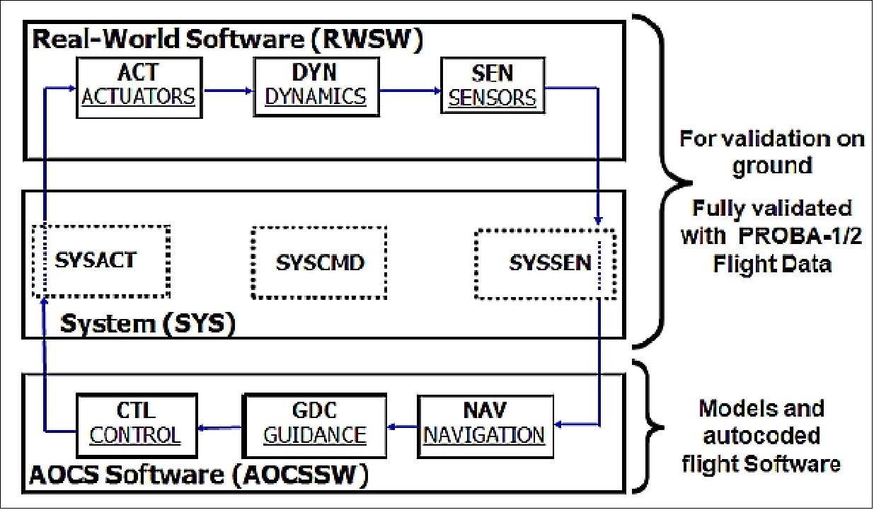
AOCS (Attitude and Orbit Control Subsystem) provides three-axis attitude control including high accuracy pointing and maneuvering in different spacecraft attitude modes. The AOCS SW is an extension of the one of PROBA-2, including the following algorithms required by the on-board autonomous mission and payload management: 26) 27)
- Prediction of land/sea transitions using a land sea mask to reduce the amount of data generated
- Optimization of attitude in Sun Bathing mode to enhance incoming power while avoiding star tracker blinding
- Momentum dumping without zero wheel speed crossings during imaging
- Estimations of remaining spacecraft magnetic dipole to reduce pointing error
- Autonomous avoidance of star tracker Earth/Sun blinding
- Inertial mode with fixed scanning rate for moon calibration.
The AOCS hardware selection for PROBA-V consists of a high accuracy double star tracker head, a set of reaction wheels, magnetotorquers, magnetometers and a GPS receiver.
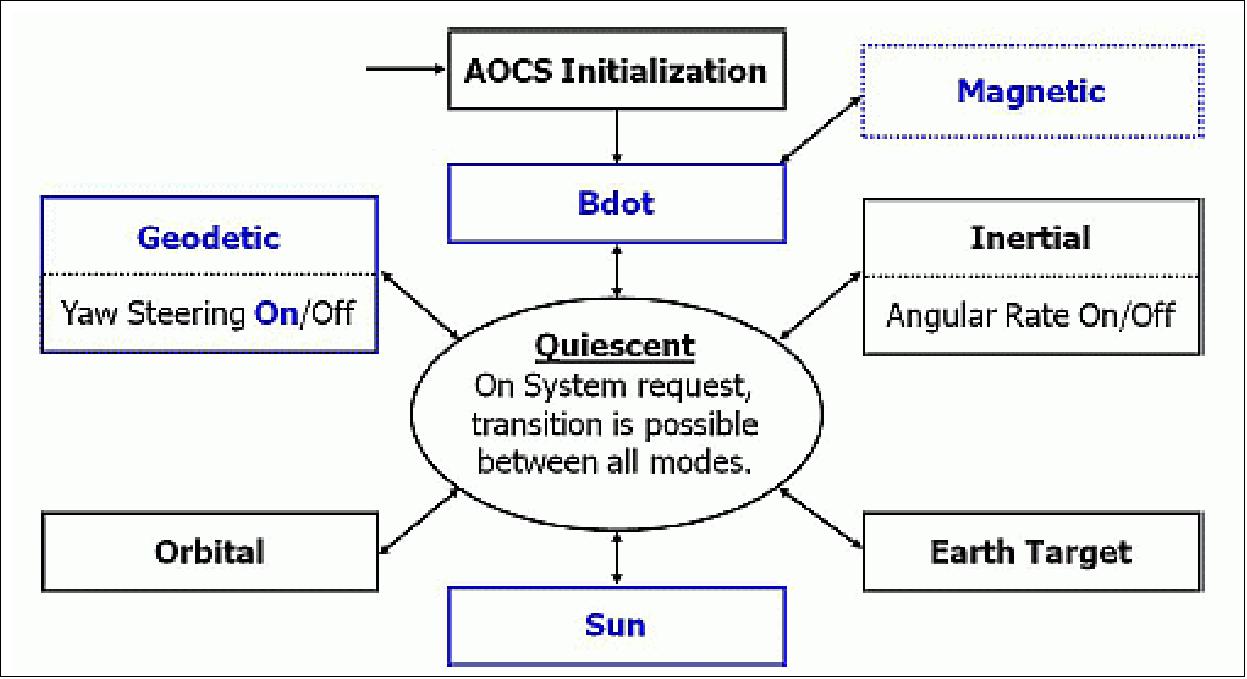
The main AOCS modes are: Safe, Geodetic, Sun Bathing and Inertial mode.
- The satellite Safe mode is used to detumble the spacecraft after separation from the launcher and it will be used to recover from spacecraft anomalies.
- The Geodetic mode is used during nominal observation of the Earth's vegetation. In this mode the payload is pointed towards the geodetic normal to the Earth's surface. An extra steering compensation, yaw-steering, is added in this mode, to minimize the image distortion caused by the rotation of the Earth. This yaw-steering maneuver ensures that the spectral imagers are oriented such that the lines of pixels are perpendicular to the ground-trace at each moment. In this mode the star trackers and the GPS receiver are used as sensors and the reaction wheels as actuators.
- On each orbit, the spacecraft enters the Sun Bathing mode from -56º latitude until entry of eclipse. This is to enhance the incoming power.
- The Inertial mode coupled with an inertial scanning of the Moon at a fixed rate is used for monthly radiometric full moon instrument calibration purposes. The pointing towards the moon takes 2.5 min, 9 min for scanning the moon and 2.5 min to return to nominal observation mode. It is sufficient to have the moon in the FOV of the SI (Spectral Imager) for a number of pixels.
NGC Aerospace of Canada was responsible for the design, implementation and validation of the autonomous GNC (Guidance, Navigation and Control) algorithms implemented as part of the PROBA-1 and PROBA-2 AOCS software and has the same responsibilities for the PROBA-V mission.
Beyond the technology demonstration through the PROBA program, it is also noted that the AOCS software technology developed in the course of this program is now the baseline of the AOCS of a major operational mission of the GMES (Global Monitoring for Environment and Security) program: Sentinel-3. NGC Aerospace Ltd (NGC) of Sherbrooke, (Québec), Canada was responsible for the design, implementation and validation of the autonomous GNC (Guidance, Navigation and Control) algorithms implemented as part of the AOCS software of PROBA-1 and PROBA-2. NGC has the same responsibilities for the PROBA-V mission (Ref. 26).
Operational Modes of AOCS
The PROBA-V operational modes are illustrated in Figure 7 (critical modes in blue) and briefly described in Table 2. Transitions between any of the modes are possible and can be commanded by the ground station or, autonomously, by the on-board mission manager. The Magnetic mode is represented in a dotted rectangle in Figure 7 because it was not part of the launch configuration. The addition of the Magnetic mode was decided and implemented after the launch. It was decided to include it as an added safety feature for PROBA-V. The Magnetic mode replaces the Bdot mode as the spacecraft Safe mode. However, the Bdot mode remains available upon ground request or as an autonomous fallback mode in case of an anomaly with the Magnetic mode. 28)
Mode | Description | Usage |
Magnetic | - Provides three-axis control using only MGM measurements, MTR (Magnetic Torquers) actuation and the RWL (Reaction Wheels) commanded at constant speeds. - Points the momentum bias axis towards the orbit normal and controls the orientation around this axis. | - Safe mode (fallback mode in case of failures) |
Bdot | - Uses the magnetic field and MTR actuation to reduce spacecraft angular rates. - Uses a momentum bias generated by commanding the RWL at constant speeds to roughly align the momentum bias axis towards the orbit normal. | - Detumbling after launcher separation |
Geodetic | - Controls the spacecraft attitude for geodetic Earth normal pointing. | Main observation mode |
Sun | - Controls the spacecraft attitude with respect to the Sun frame. | Outside of imaging to maximize incoming power |
Orbital | Controls the spacecraft attitude with respect to the orbital frame. | Nadir pointing |
Inertial | - Controls the spacecraft attitude with respect to the inertial frame. | Payload calibration Moon scanning maneuvers |
Earth target | Controls the spacecraft attitude in order to point to a fixed Earth target. | Pointing to an Earth target |
Quiescent | Sets all control outputs to zero. | Used for mode transitions |
The requirements for the PROBA-V AOCS software were first defined by QinetiQ Space. Then, NGC (NGC Aerospace Ltd.) completed the software design and the related validation tests. Finally, NGC and QinetiQ Space conducted, in close collaboration, the AOCS Software Acceptance Tests (SAT). In addition to this on-ground validation, prior to the addition of the Magnetic mode, the AOCS software was validated in flight. For this purpose, the various AOCS software functions and operational modes were activated and validated one at a time in an incremental manner in the weeks following the launch. This validation successfully demonstrated that the AOCS software meets the stringent PROBA-V requirements.
With the addition of the Magnetic mode, the validation process had to be followed again not only for the Magnetic mode, but to ensure non-regression of the already fully validated operational modes. The validation approach followed for the addition of the Magnetic mode is described in the next section after an overview of the Magnetic mode algorithm and of its implementation.
Magnetic mode design: The reader is referred to Ref. 28) , since this is a too lengthy discussion. However, from the in-flight results, it can be stated that the Magnetic mode meets its requirements both in terms of functionality and robustness. Indeed, it has been demonstrated that the spacecraft attitude is controlled as required and that maneuvers can be performed.
Since its successful in-flight validation, the Magnetic mode is the baseline Safe mode for PROBA-V. With its successful operation on-board PROBA-V, the Magnetic mode provides an alternative to the traditional B-dot algorithm for safe modes of missions where it might be desired to maintain three-axis pointing in order to point one of the spacecraft axis (e.g. antenna) towards the Earth.
The PROBA-V design was successful in meeting the challenges as can be seen by the pointing performance achieved in flight (Table 3).
Parameter | Requirement | Achieved in Flight |
AKE (Attitude Knowledge Error) | 5 arcsec (95%) | 5 arcsec (95%), Note: AKE cannot be exactly evaluated in flight. However, the geolocation accuracy indicates that the requirement is met. |
APE (Absolute Performance Error) | 360 arcsec (95%) | < 20 arcsec (95%) |
RPE (Relative Performance Error) | 80 arcsec over 1.5 sec (95%) | < 1.5 arcsec over 1.5 sec (95%) |
EPS (Electric Power Subsystem): The PVA (Photo-Voltaic Array) uses GaAs triple junction cells with an of efficiency of 28%. To obtain the operating voltage of 31.5 V, 18 cells are included in each string in series with a blocking diode. The PVA consists of a total of 25 solar strings taken into account the loss of one string on the most contributing PVA panel. The average solar string power under EOL conditions (summer solstice and T = 40°C) yields 12.8 W. The maximal incoming power at EOL during an orbit is 144 W. The energy budget for PROBA-V is derived for a bus power consumption of 140 W assuming a worst case day in the summer and while not taken into account the effect of albedo. A worst case power budget analysis indicated a maximum capacity discharge of 1.66 Ah. Use of a Li-ion battery. The battery cells provide a capacity of 1.5 Ah per string. The PROBA-V battery is sized to 12 Ah taking into account capacity fading and loss of a string.
RF communications (PROBA-V): S-band for TT&C transmissions and low-gain antennas with omni-directional up- and downlink capability. The uplink symbol rate will be fixed at 64 ks/s, while the downlink can be set to a high rate (< 2 Ms/s) for nominal imaging or to a low rate at 329 ks/s for off-nominal conditions. The CCSDS protocol is used for the TT&C transmissions.
X-band downlink of the payload data is in X-band at a data rate of 35 Mbit/s. The onboard mass memory is 88 Gbit. The Redu station (Belgium) is being used for TT&C communication services. The X-band uses two cold redundant high-rate X-band transmitters (developed by Syrlinks, France) and two nadir pointing isoflux antennas, both RHCP.
The S-band transceivers will be connected to RS422 outputs (cross strapped) of ADPMS while the X-band transmitters (8090 MHz) will be connected to the LVDS outputs not cross-strapped. The X-band link budget results in a link margin of 6 dB which will allow a reduction of the RF output power. Therefore the X-band transmitter will be designed (customer furnished item) to support various output power settings such that after commissioning, a lower output power might be selected.
Data compression: The massive amount of data produced by the instrument is beyond the capabilities of the bandwidth available on board of a small satellite. Data are reduced by using a lossless data compression algorithm implemented in a specific electronics. The data compression ratio obtained using standard CCSDS compression algorithms (CCSDS 133.0 B-1) is shown in Table 4.
Spectral band | Compression ratio |
Blue | 10.8 |
Red | 7.2 |
NIR | 5.4 |
SWIR | 2 |
The CCSDS image data compression standard turned out to meet all the requirements in terms of image quality and reachable compression ratio, accordingly reaching the required target data rate. This compression algorithm has been implemented in specific electronics (FPGA) on the satellite. Among many other notable firsts, PROBA-V has therefore become the first European mission to fly the CCSDS image data compression standard.
The selection of an S-band transceiver and the development of an innovative and generic X-band transmitter for small satellites has been initiated in a collaborative program between CNES and ESA and is funded under GSTP-5 (General Support Technology Program-5). The X-band transmitter is a high-performance device optimized for the needs and constraints of small platforms for which small volume, low mass, low power consumption, and low cost cost are important parameters. Moreover, some key features such as modulation (filtered Offset-QSK), coding scheme (convolutional 7 ½), data and clock interfaces (LVDS packet wire serial interface) have been selected in compliance with CCSDS recommendations, but also to ease the interoperability with most of the existing on-board computers and ground station demodulators. 29)
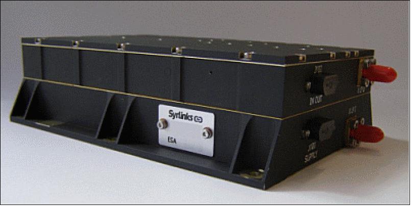
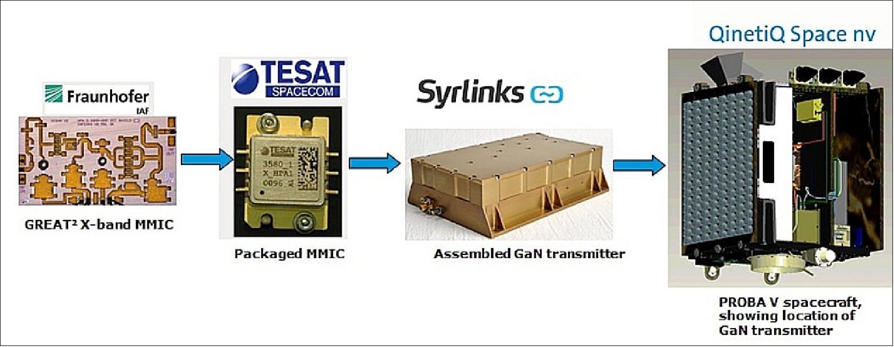
Following CNES studies under ESA contract, two low-cost X-band transmitters compatible with data rates up to 100 Mbit/s were designed and manufactured by Syrlinks of Bruz, France. One transmitter uses a GaAs RF power amplifier and one X-band transmitter uses a new GaN (Gallium Nitride) RF power amplifier, part of ESA's developed GREAT2 (GaN Reliability Enhancement and Technology Transfer Initiative). 30) 31)
The development of the new X-band transmitter is based almost exclusively on COTS components to achieve at the same time high performances and low recurrent cost. The transmitter also features an innovative functionality with an on-board programmable RF output power from 1-10 W which allows to match finely with the chosen bit rate, and to reduce as much as possible the margins of the link budget and therefore the consumption power. PROBA-V is the first mission to use this newly developed transmitter. The transmitter has a mass of 1 kg, a size of 160 mm x 115 mm x 46 mm, an in-orbit life time of 5 years, and a radiation hardness of 10 krad. Data rates from 10-100 Mbit/s are available.
Output frequency | 8025 - 8400 MHz range |
RF output power | +30 dBm to +40 dBm, programmable in-flight by 1 dB step |
Modulation | Filtered OQPSK (CCSDS compatible) |
Bit rate | Up to 100 Mbit/s |
Coding | Convolutional 7 ½ , Q signal inverted |
HKTM (Housekeeping Telemetry) | Analog, CMOS, RS422 |
Data and clock | LVDS |
Power supply voltage | From 20 to 32 V |
Power consumption | < 30 W for +38 dBm RF output |
Size, mass | 160 x 115 x 46 mm, 1 kg |
Life time at LEO (Low Earth Orbit) | > 5 years |
Temperature range - operational | -30ºC / +40ºC |
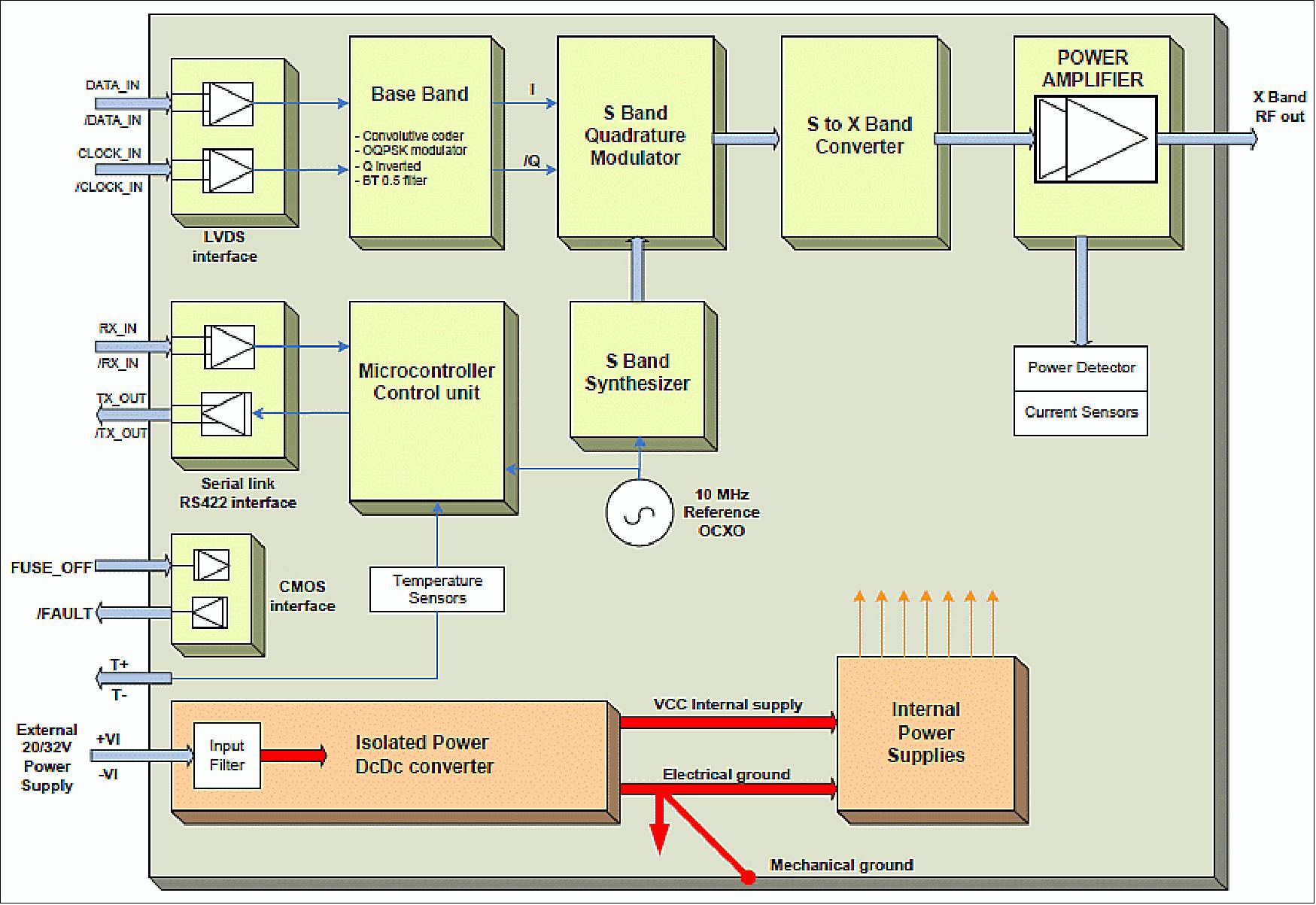
Incoming telemetry data is coded in a programmable device (CPLD) at the clock rate. I and Q baseband signals are filtered (7th order Butterworth filter) and then applied to the RF I/Q modulator. This modulator works in S-band. The S-to-X converter translates the modulated signal from S-band to X-band. X-Band signal is then amplified. The microcontroller manages the serial link with the OBC (On-Board Computer) of the platform. It decodes the commands and executes the actions. The microcontroller reads the different internal indicators (temperature, currents, ...) and controls the functions such as the RF synthesizer or the power supplies. The power supply is a galvanic isolated Dc/Dc converter followed by non-isolated Dc/Dc converters and linear regulators. Internal supplies are protected against over-current consumption, in case of latch-up.
The GaAs and GaN transmitter measured performances are similar. Table 6 gives the main typical results.
Power consumption @ +25ºC, @ +38 dBm RF power | < 30 W |
RF Power consumption (Drivers & PA) @ +25ºC, @ +38 dBm RF power |
|
Harmonic rejection | > 50 dBc |
Local Oscillator rejection | > 40 dBc |
OCXO frequency stability |
|
Output phase noise - CW |
|
Implementation Loss @ BER = 1 x 10⁻⁵ | < 0.4 dB |
Channel frequency width (99% Power) | < 80 MHz at 42 Mbit/s |
Output return loss | < -12 dB |
Resistance to accumulated radiation dose (TID) (Si level) | 20 krad |
• June 25, 2015: Europe's first item of high-performance gallium nitride technology to fly in space has completed its second year of operations. Hosted on ESA's Earth-observing PROBA-V minisatellite in 2013 as a test prototype, the transmitter is today used routinely to return mission imagery to the ground. "The X-band transmitter in question incorporates an experimental gallium nitride (GaN) amplifier," explains Andrew Barnes, overseeing ESA's work in GaN. "It is still working seamlessly today after two years in orbit, showing no drift in performance" (Ref. 31).
- The GaN-based transmitter is used to downlink data to PROBA-V's Kiruna ground station – in the Swedish Arctic – once per orbit for a week at a time, alternating with a second transmitter using a conventional gallium arsenide amplifier.
- With its data coming down at a standard rate of 42.22 Mbit/s during each roughly 12 minute pass, the m3-sized PROBA-V builds up a complete picture of all Earth's vegetation cover every two days.
- Access to the GaN-based transmitter also increases the operational flexibility of the satellite – in principle its data rate can be boosted to 100 Mbit/s , while its programmable radio frequency output power can also be increased as needed, while operating at a lower voltage than its conventional equivalent.
- Gallium nitride has been described as the most promising semiconductor since silicon, capable of operating at much higher voltages and temperatures than comparable materials. As an additional advantage, GaN also possesses inherent resistance against the radiation encountered in space.
- "In terms of communications for space, GaN offers a five- to ten-fold increase in communications power, while requiring no additional cooling systems," adds Andrew.
- "Its promise is such that back in 2008 ESA launched the ‘GaN Reliability Enhancement and Technology Transfer Initiative' (GREAT2), bringing together leading universities, research institutes and industry to develop space-compatible production processes for making GaN microwave power transistors and integrated circuits.
- With GREAT2 , ESA has come in at an early stage of industrialization to ensure that the resulting products meet the demanding requirements of space use, such as resistance to shock and temperature extremes, as well as continuous operations for years at a time."
- The GREAT2 partners include UMS (United Monolithic Semiconductors) based in Germany and France, responsible for the industrial foundry used for manufacturing GaN products.
- Since then, while the transmitter has been proving its worth in space, the first industrial prototypes have successfully completed their testing for reliability and robustness.
- "As a result of GREAT2 we were able to place the UMS GaN manufacturing process onto the European Preferred Parts List of the European Space Components Coordination – a list of recommended parts for space missions – in 2012," adds Andrew. "This was two years earlier than originally planned.

Legend to Figure 13: The minisatellite is seen sitting on top of the VESPA system containing two other satellites, VNREDSat-1 and ESTCube-1. The Vega launcher fairing is seen in the background. 33)
Feature | Description |
Spacecraft mass | 138 kg |
Dimensions | 765 x 730 x 830 mm |
Power | · 28V battery unregulated bus |
Structure | Aluminium honeycomb H-structure |
Payload mass | 33.3 kg |
Data handling | · ADPMS onboard computer with LEON2 processor. |
Communications | · Platform data (S-band): 64 ksps uplink / 830 kbps downlink; Internally redundant transceiver - STT (Germany) |
Attitude control | · 3-Axis stabilized |
AOCS | · Actuators: 3 magnetotorquers - Zarm (Germany); 4 reaction wheels - Rockwell Collins (Germany) |
Software | · OS: RTEMS (Real-Time Executive for Multiprocessor Systems) |
PVCC (Proba-V Companion CubeSat)
Mission Overview
PROBA V-CC (PVCC), which is an acronym for “Project for On-Board Autonomy – Vegetation – Companion CubeSat”, is an ESA in-orbit demonstration initiated by VITO Remote Sensing that aims not only to compare the performance of a payload designed for a small satellite on a CubeSat platform, but also to achieve high-quality Earth observation data suitable for monitoring global land surfaces and analysing the impact of climate change. 124)
PVCC hosts the spare Spectral Imager from the Proba-V mission on a 12 units (12U) CubeSat. The mission is an Earth Observation In-Orbit Demonstration (IOD) conducted under the support of the European Space Agency (ESA) through the GSTP (General Support Technology Program) Fly program. It aims to prove the technical capabilities of Aerospacelab in providing an ambitious satellite platform with a strong flexibility and versatility by incorporating external components at the request of its customers.
The operational purpose of PVCC is to provide data to support the calibration of CubeSat Earth observation missions. Since the beginning of Aerospacelab, its developments have been conducted within an agile framework by relying as far as possible on Commercial Off-The-Shelf (COTS) components qualified for the space environment. The technical purpose of PVCC is to test the performance of a known payload flown on Proba-V and provided by OIP, on a 12-units CubeSat platform built in-house; this point is the core of the innovative feature of the mission. Indeed, PVCC relies on several technologies embarked on Aerospacelab’s first satellite, ARTHUR-1, launched in 2021, and for the PVCC mission, some components have been improved and developed due to the different interface between the Proba-V instrument and the platform. Hence, the mission will focus on testing:
- New Data Handling Unit (DHU) and Power Supply Unit (PSU) electrical interfaces
- New payload manager software
- New compression algorithm in the software
- The update of the Baffle design and related manufacturing process
- New optical bench mechanical interface and thermal insulation
- The integration of a known payload on a CubeSat platform
The production and quality assurance staff are working closely to ensure a tight feedback loop. The development also includes regular hardware-in-the-loop testing allowing the complete verification of the whole mission.
Mission Objectives
The primary objective of the PVCC mission is to deliver images from a known payload, OIP VGT instrument, on a tailored CubeSat platform. If this objective is achieved, the PVCC mission will thus support the calibration of CubeSats used for Earth observation imagery by testing the VITO future product CalibrEO, which is not part of the mission, but developed in parallel.
Additionally, a secondary objective has been identified within the frame of a strategic partnership between ESA and a New Space company. As PVCC is an in-orbit demonstration mission, its success will allow the development of business relations with ESA and other public actors. More generally, PVCC is an opportunity for Aerospacelab to demonstrate its expertise on a vertical manufacturing processing while caring about the customers’ needs and expectations through the integration of external components in its own design and structures.
Mission Characteristics
As the payload was designed for a different direct environment, namely on the mechanical loads, the mission is made possible through the use of a load isolation system integrated in the CubeSat deployer. As there is no propulsion on-board, the orbit will remain the same for the duration of the mission, with an altitude that will slowly decrease due to residual atmospheric friction.
The baselined ground stations to communicate with the PVCC spacecraft for Telecommand and Monitoring (TM/TC) are Redu, Belgium (ESEC/REDU) and Kiruna, Sweden (Swedish Space Corporation, SSC). There are two Payload Data Ground Stations located in Kiruna, Sweden (SSC) and Inuvik, Canada (SSC). 122)
Launch
PROBA-V
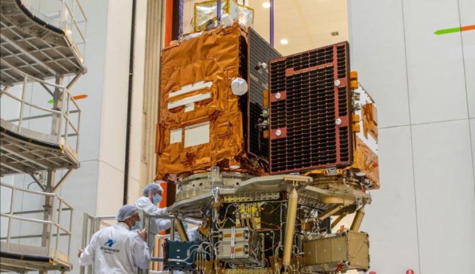
The PROBA-V spacecraft (primary payload) was launched on May 7, 2013 (02:06:31 UTC). The launch vehicle was Vega (with Arianespace as launch provider); the launch site was the Guiana Space Center, Kourou. This marks the first VERTA (Vega Research, Technology and Accompaniment) flight of VEGA (designated as VERTA-1). The mission is designated Flight VV02 in Arianespace's numbering system. 34) 35) 36)
The secondary payloads on this flight were:
• VNREDSat-1A (Vietnam Natural Resources, Environment and Disaster-monitoring Satellite) of STI-VAST (Space Technology Institute-Vietnam Academy of Science and Technology). The microsatellite VNREDSat-1A (115.3 kg) has been built by EADS Astrium, Toulouse, France. 37) 38)
• ESTCube-1 (Estonian Student Satellite-1), a 1U CubeSat (1.3 kg) technology demonstration mission of the University of Tartu.
PROBA-V will ride in the upper position of the VESPA (Vega Secondary Payload Adapter), while VNREDSat-1A and ESTCube-1 will sit in the lower position in the structure. The upper stage of the Vega vehicle is a liquid propulsion module with multiple re-ignition capability. The secondary payloads will be deployed last after re-ignition of the Vega upper stage.
Orbit of PROBA-V: Sun-synchronous orbit, altitude = 820 km, inclination = 98.8º, LTDN (Local Time on Descending Node) = 10:30 hours (with a drift limited between 10:30 and 11:30 AM during the mission lifetime). Note: In contrast to the SPOT-4 and SPOT-5 missions, PROBA-V will not have the capability to maintain its orbit.
Orbit of VNREDSat-1 and ESTCube-1: Sun-synchronous orbit, altitude =704 km, inclination = 98.7º. VNREDSat-1A was released 1 hour 57 minutes into flight. ESTCube-1 was ejected from its dispenser three minutes later. A last burn will now place the spent upper stage on a trajectory that ensures a safe reentry that complies with new debris mitigation regulations.
PROBA-VCC
The PROBA V-CC (PVCC) satellite lifted off from Europe’s spaceport in Kourou, French Guiana, on October 9th at 01:36 AM UTC on a Vega rocket. Aerospacelab successfully established communication with the satellite, which is in good health, a few hours after the launch.
Orbit
Sun-Synchronous Orbit (SSO) at an altitude of 564 km and a Local Time of Ascending Node of 22:30.
Mission Status
• October 9, 2023: Aerospacelab has successfully launched the PVCC satellite with support from the European Space Agency (ESA) and the Belgian Science Policy Office (Belspo). This mission will support the space community’s ongoing efforts in providing insightful Earth Observation data that will help in monitoring vegetation conditions, and analysing climate change. 121)
• July 9, 2020: ESA's PROBA-V minisatellite has ended its seven-year global mission to monitor the daily growth of all Earth's vegetation. PROBA-V was launched in 2013 to fill the gap in global vegetation monitoring between the end of France's Spot satellites and Copernicus Sentinel-3. 39)
- Overall, the PROBA-V mission has acquired more than a petabyte (>1015 bytes) of environmental data during its time in orbit, which was processed and distributed to the users by VITO, the Belgian research and service center.
- Its observing mission having ended at the end of June, PROBA-V is now free to perform experimental monitoring over Europe and Africa - including co-observation with new companion missions.
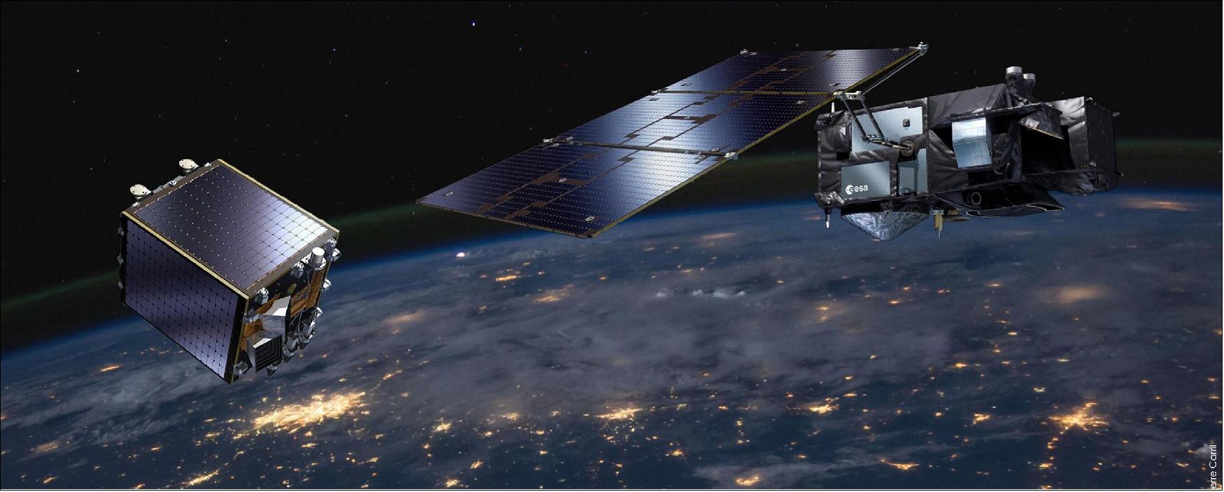
• April 20, 2020: ESA's cubic-meter-sized PROBA-V minisatellite will soon end its nearly seven-year global mission to monitor the daily growth of all Earth's vegetation. As Copernicus Sentinel-3 takes on this task instead, PROBA-V will be free to perform experimental monitoring over Europe and Africa – including co-observations with new companion missions. 40)
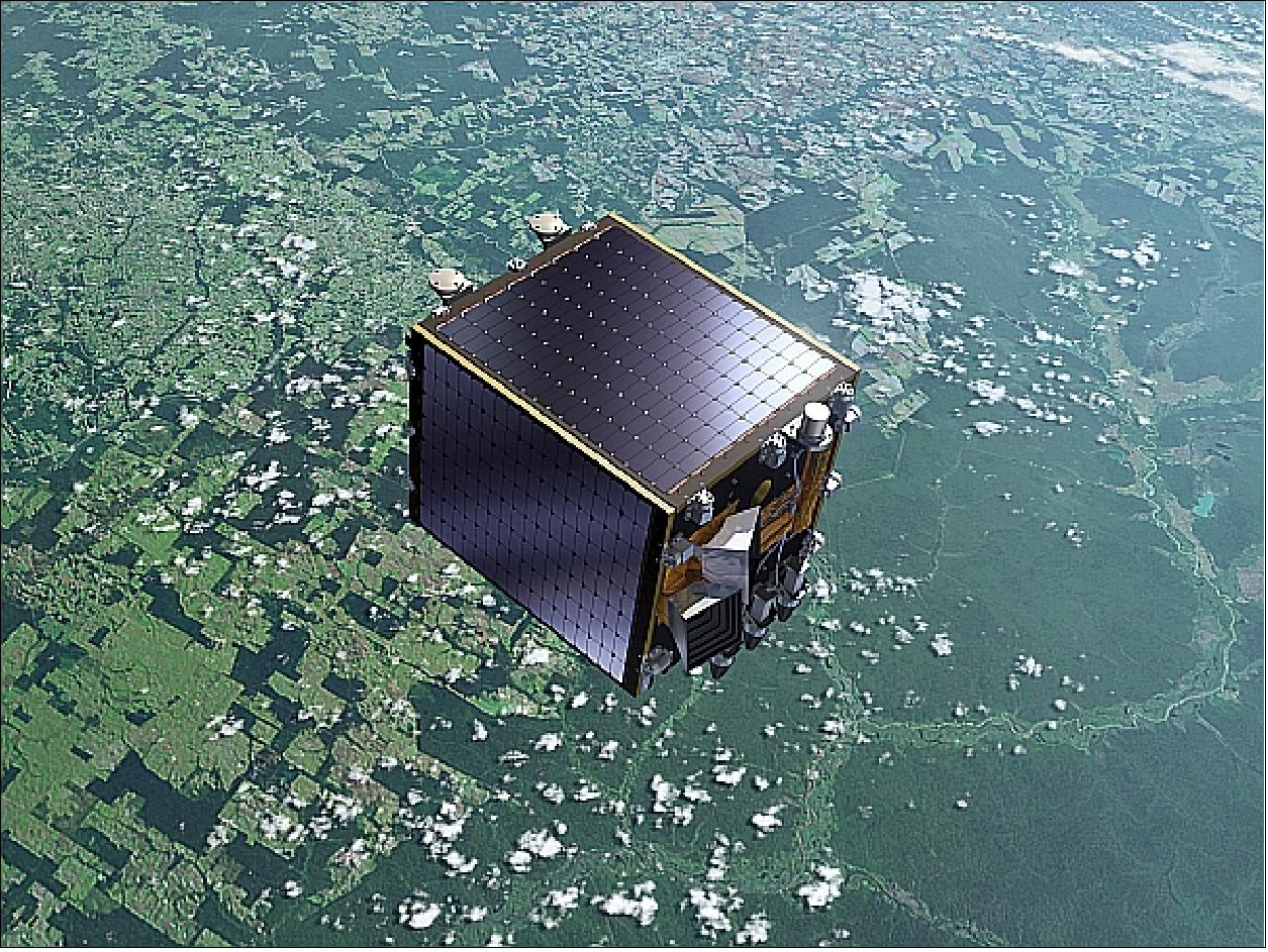
- Despite its small size, PROBA-V maintains a continent-spanning perspective: its main Vegetation imager has a 2250-km wide swath. This enables it to cover nearly the entire vegetated surface of the globe every day. Allowing for cloud cover, the mission builds up a complete snapshot of global plant growth every 10 days. Overall, the mission has acquired more than a petabyte of environmental data during its time in orbit.
- PROBA-V's extremely wide view comes about because Vegetation is made up of three separate imaging telescopes, possessing 300 m spatial resolution, which rises to 100 m resolution in the central telescope – a marked improvement on the previous generation of Vegetation instruments.
- "PROBA-V began as a ‘gap-filler' mission to ensure data coverage between the Vegetation instruments flown on the full-sized Spot-4 and -5 satellites and Copernicus Sentinel-3," explains ESA Earth Observation operations manager Roberto Biasutti.
- "It started with a two-year mission lifetime, which was repeatedly extended, and the satellite remains in excellent overall health. So even though its global mission is due to end this June, shortly after its seventh birthday, the plan is to let it go on working."
- PROBA-V was launched into what is called a ‘Sun-synchronous' orbit, where it keeps pace with the Sun as it circles Earth at 820 km altitude, allowing it the maximum possible observing daylight. This orbit is gradually decaying however, and the minisatellite lacks onboard thrusters to correct it. Tugged by the gravitational pull of Earth's equatorial bulge, its observing time is gradually growing earlier in the local morning.
- "Basically one of the cameras on PROBA-V will soon be observing night-time rather than daylight, meaning it cannot go on delivering daily global coverage anymore to continue the 20 year plus Vegetation time series, so its operational global mission has to end," comments Dennis Clarijs of VITO, the Belgian research and service center processing and distributing PROBA-V data to users.
- "But this isn't the end of the mission. Instead ESA will be applying its excellent geometric and radiometric performance to make test observations in Europe and Africa, particularly the African Sahel where its results help provide early drought warnings.
- "This means the more than 1800 research teams making use of PROBA-V data today still have more data to look forward to, albeit on an experimental rather than operational basis. This is good because its 100-m imagery fills a particular niche, as a midway step between Copernicus Sentinel-2 and -3, able to resolve individual field delineations in some cases. PROBA-V's 100-m imagery is also routinely used to cross-check other products, such as the Copernicus Global Land Service."
- PROBA-V will also be increasing its observations of the Moon. It is not generally known, but many Earth observation satellites routinely observe our planet's natural satellite along with Earth itself: the unchanging state of the lunar surface makes it an excellent calibration target.
- In the past PROBA-V made such lunar acquisitions on a monthly basis. Now the minisatellite will increase them, experimenting with changing frequencies and view angles for the benefit of future Earth-observing missions.
- In addition, the plan is to launch in 2021 an additional tiny satellite carrying a single telescope version of the same Vegetation imager aboard PROBA-V.
- Roberto comments: "This companion mission is currently being developed by Belgian startup Aerospace Lab for launch next year. Based on a tiny 12-unit CubeSat - built up from standardized 10 cm cubic units – it will image the same targets as PROBA-V areas at the same time except from a different viewing angle, allowing the creation of combined ‘fusion' image products.
- "A major motive behind the original PROBA-V mission was to see if an instrument previously hosted on a full-sized satellite could do good work from a smaller platform. With this companion satellite we will raise the bar, using an even smaller, cheaper platform."
- Another companion satellite is also being planned, to host either a thermal infrared imager or an hyperspectral instrument, both of which would offer valuable synergies with Vegetation observations, and test the feasibility of small satellite constellations entering operations in the future.
- PROBA-V's orbital decay will finally bring it into complete darkness in October 2021, when it will either be shut down, or placed in suspended animation, awaiting a time when its orbit brings it into daylight again.
- "There is a precedent for such an arrangement," adds Roberto, "with predecessor mission PROBA-1, launched back in 2001, hosting a hyperspectral camera. Having passed through such a period of orbital darkness it is still observing to this day."
• October 21,2019: ESA's PROBA-V catches smoke plumes rising from the island of Borneo. 41)
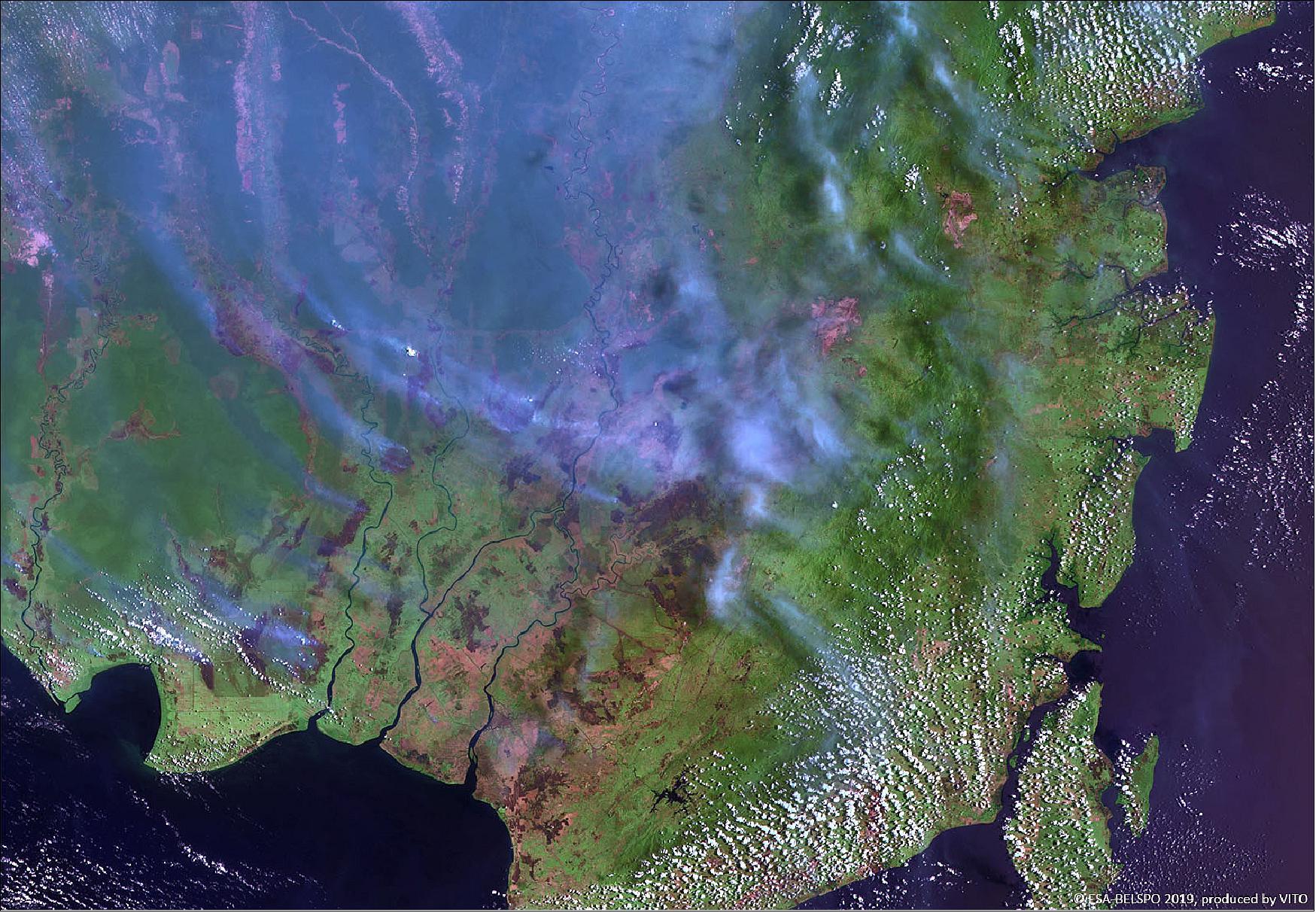
- In this area, fires are common in September and October as farmers burn agricultural and logging debris to clear the way for crops and livestock and to prepare the land for new plantings of oil palm and acacia pulp.
- This year, however, the fire season was more intense and the thick smoke caused schools to close, impacted air traffic and triggered health warnings from poor air quality.
- These peat fires can linger for months, until the wet season arrives, during which they emit high levels of greenhouse gases carbon dioxide and methane.
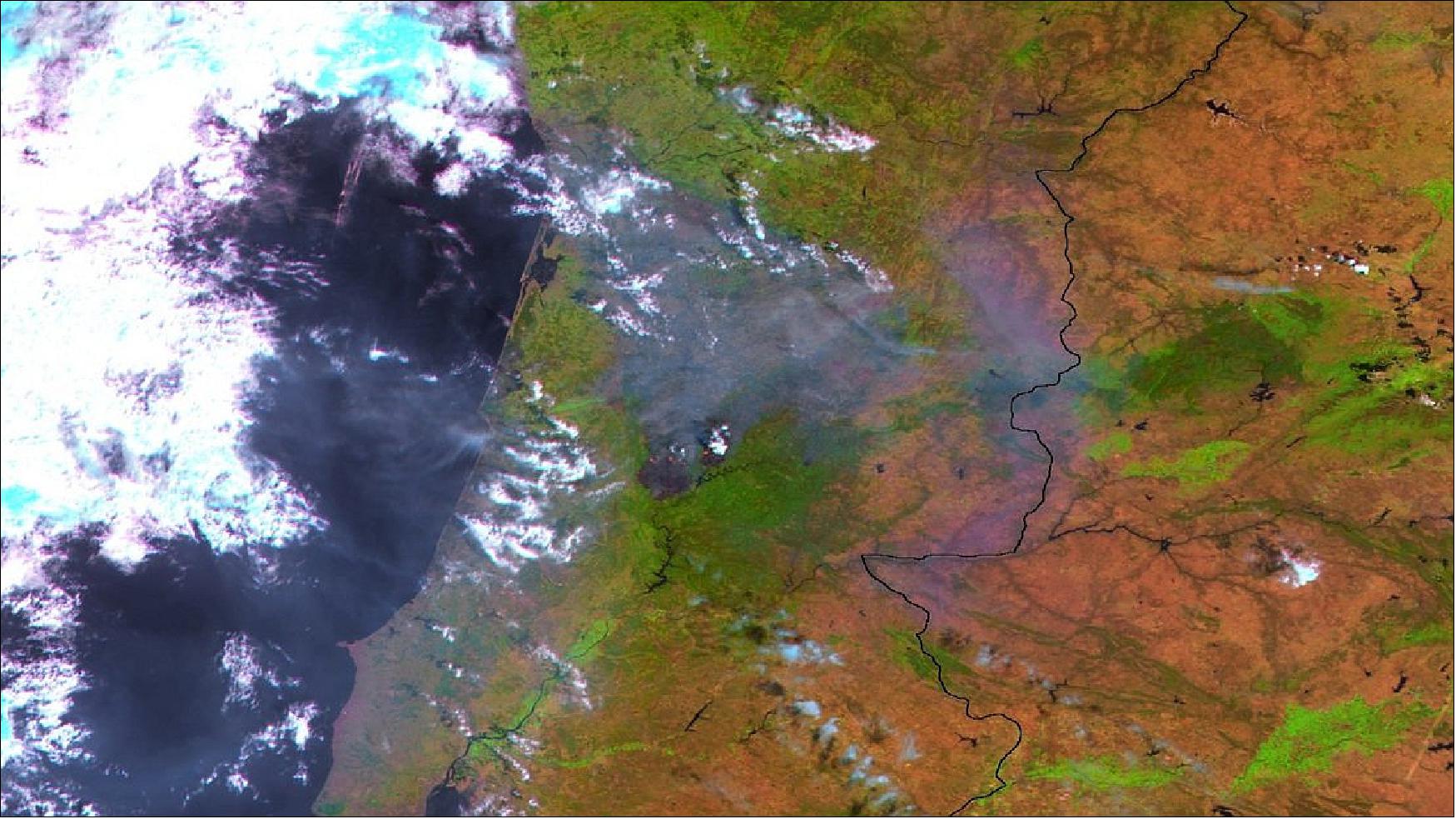
• July 24, 2019: ESA minisatellite PROBA-V's ongoing view shows the rapid regeneration of South American grasslands from wildfire burn scars. 42)
- ESA minisatellite PROBA-V's ongoing view shows the rapid regeneration of South American grasslands from wildfire burn scars.
- The fertile Pampas, grasslands located in northern Argentina, Uruguay and southern Brazil, are frequently struck by wildfires. During the southern hemisphere summer of 2016-2017 fires burnt across 30,000 km2 in the La Pampa and Rio Negro provinces of Argentina.
- Strong winds, high temperatures and dry conditions contributed to the devastation, but rain in late December helped firefighters regain control – although a few hotspots persisted in early January.
- Launched on 7 May 2013, PROBA-V is a miniaturized ESA satellite tasked with a full-scale mission: to map land cover and vegetation growth across the entire planet every two days.
- Its main camera's continent-spanning 2250 km swath width collects light in the blue, red, near-infrared and mid-infrared wavebands at a 300 m pixel size, down to 100 m in its central field of view.
- VITO Remote Sensing in Belgium processes and then distributes Proba-V data to users worldwide. An online image gallery highlights some of the mission's most striking images so far, including views of storms, fires and deforestation.
• June 12, 2019: Chilean capital Santiago – among the largest conurbations in South America – viewed in false color from ESA's PROBA-V minisatellite, with vegetation in red. - This December, Santiago will help set humankind's future hosting the latest United Nations Climate Change Conference, the 25th session of the Conference of the Parties (COP 25). 43)
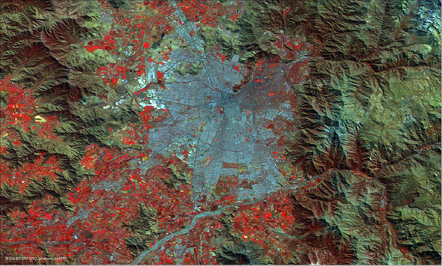
- Sitting in a valley between the Chilean Coastal Range and the Andes Mountains, Santiago experienced explosive growth over the course of the last century. Today it is the fifth-largest city in South America, with a population of more than five million, and seven million people living within its overall metropolitan area.
- In such a densely populated area, open space becomes all the more valuable. Note the hilly Santiago Metropolitan Park, seen as a dark mark running northeast of the center. The double red patch just below and left of the city center is the rectangular O'Higgins Park, right, with the Club Hípico de Santiago racecourse to its left.
- Santiago Airport, the largest in Chile, is visible to the northwest of the city center.
- VITO Remote Sensing in Belgium processes and then distributes PROBA-V data to users worldwide. An online image gallery highlights some of the mission's most striking images so far, including views of storms, fires and deforestation.
- More than half the world's population live in cities. Space plays an important role in urban innovation, improving the quality of life of millions – and potentially billions – of people. This week, we take a look at what ESA is doing to benefit city dwellers. Join the conversation online by following the hashtag #SmartCities.
• May 15, 2019: The snow-capped peaks of the Southern Alps stretch more than 500 km northeast to southwest across New Zealand's South Island, imaged here in the southern hemisphere's winter by ESA's PROBA-V minisatellite – now completing its sixth year on orbit. 44)
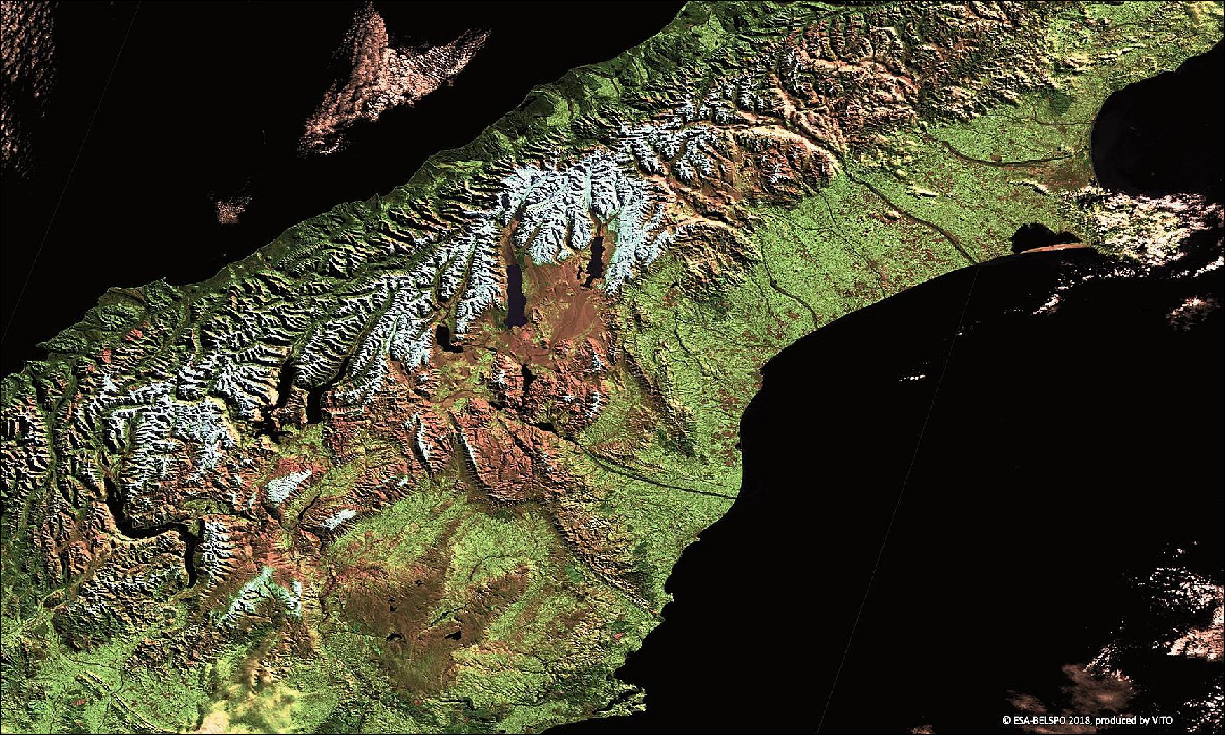
- Comprising 23 peaks above 3 000 m altitude, the glacier-lined Southern Alps are visited by more than half a million tourists annually. The mountains are located within a continuous tract of protected lands along the entire length of the island, made up of five national parks.
- Mount Cook, otherwise known by the Maori name Aoraki, is the tallest of the Southern Alps at 3,724 m. It is visible here in the middle of the mountain chain, with the long glacial Lake Pukaki below it.
- Launched on 7 May 2013, PROBA-V is a miniaturized ESA satellite tasked with a full-scale mission: to map land cover and vegetation growth across the entire planet every two days.
- Its main camera's continent-spanning 2250 km swath width collects light in the blue, red, near-infrared and mid-infrared wavebands at a 300 m pixel size, down to 100 m in its central field of view.
- VITO Remote Sensing in Belgium processes and then distributes PROBA-V data to users worldwide. An online image gallery highlights some of the mission's most striking images so far, including views of storms, fires and deforestation.
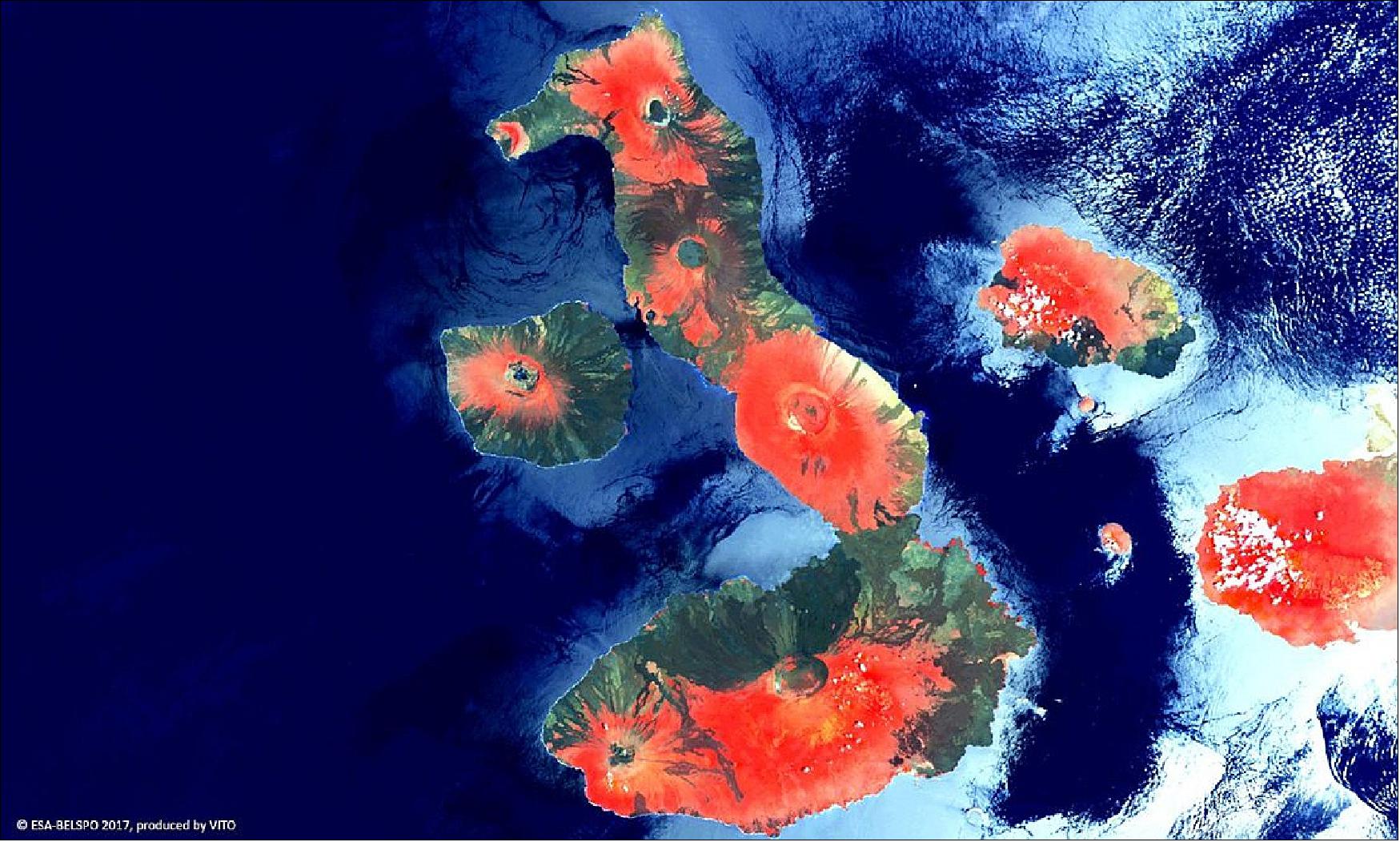
• March 27, 2019: A PROBA-V view of the internationally protected, volcanic archipelago of the Galápagos and its surrounding marine reserve. This island chain is renowned for its many endemic species that were studied by Charles Darwin, directly contributing to his famous theory of evolution by means of natural selection. 45)
- In 1535, the Spaniard Tomás de Berlanga, fourth bishop of Panama, first visited these islands by chance when he was sailing to Peru. On the maps of Mercator and Ortelius, famous geographers, the islands were named Insulae de los Galopegos or Islands of the Tortoises after the giant tortoises found there.
• February 15, 2019: The rapid evolution of Egypt's Nile Delta over the last four years, as viewed from ESA's PROBA-V microsatellite. Think of it as a small token of our love for planet Earth: just a cubic meter in size, PROBA-V maps land cover and vegetation growth across the entire world every two days. 46)

- Launched on 7 May 2013, the mission's continent-spanning 2250 km field of view collects light in the blue, red, near-infrared and mid-infrared wavebands, ideal for monitoring plant and forest growth as well as inland water bodies. Its imager has 300 m spatial resolution, increasing to 100 m within its central view.
- VITO Remote Sensing in Belgium processes and then distributes PROBA-V data to users worldwide. With more than five years of PROBA-V imagery now collected, VITO has created a new 2019 image calendar with a set of before-and-after comparisons to highlight the dynamic nature of our home planet.
- PROBA-V data is freely available to everyone. The new Mission Exploitation Platform offers on-demand processing power allowing users to create time-series comparisons and animations.
• January 9, 2019: This PROBA-V view (Figure 27) shows all that is left of the Aral Sea, once one of the four largest lakes in the world and now one of the world's major ecological disaster areas. It has shrunk into separate lakes, surrounded by Earth's youngest desert. The Aral Sea was once a large land-locked lake between Kazakhstan in the North and Uzbekistan in the South, possessing an area of 68,000 km2 – twice that of Belgium. 47)

- However, the Aral Sea has dramatically shrunk since the 1960s when Soviet irrigation projects diverted water from the rivers supplying it. By the 2000s, the lake had shrunk to about 10% of its original size and by 2014 the horseshoe-shaped Southern Lake had virtually dried up.
- Groundwater levels also fell, vegetation was laid waste and a once-thriving fishing industry collapsed. The exposed lakebed formed the newly-christened Aralkum Desert, spawning pesticide-laced sandstorms that can reach as far as the Himalayas.
- Efforts to stabilize the situation are ongoing, including the replanting of hardy vegetation to reduce sandstorms. In 2005, the Kok-Aral Dam was completed to restore water levels in the Northern Lake –located at its bottom-east side. In addition, a sluice is periodically opened to replenish the Southern Lake.
- VITO Remote Sensing in Belgium processes and then distributes PROBA-V data to users worldwide. An online image gallery highlights some of the mission's most striking images so far, including views of storms, fires and deforestation.
- PROBA-V is currently the subject of ESA's latest ‘citizen science' competition, requesting teams to produce ‘super-resolution' images equivalent to its 100 m mode from sets of 300 m imagery.
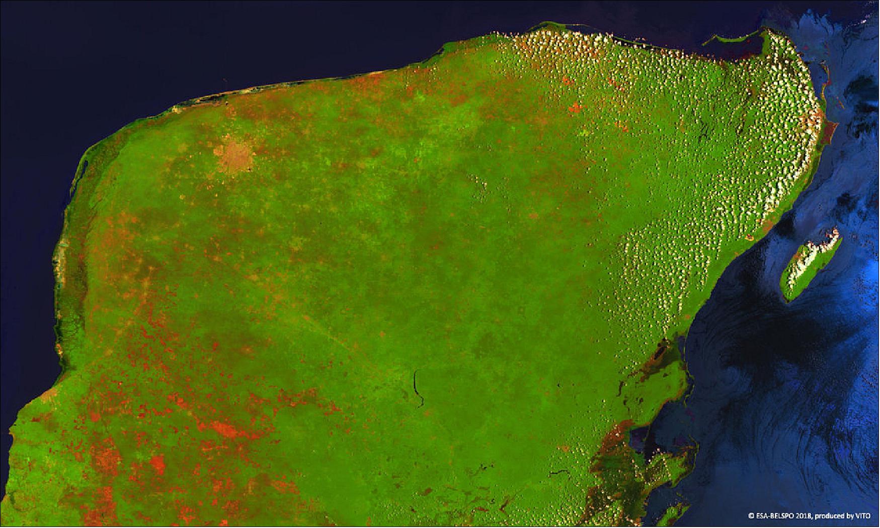
• November 7, 2018: ESA's PROBA-V minisatellite images the verdant Yucatán peninsula, once home to the Maya civilization and the site of the impact believed to have doomed the dinosaurs. 48)
- As part of the Atlantic Hurricane Belt – placed between the Gulf of Mexico to the west and the Caribbean Sea to the east – the largely flat peninsula is vulnerable to storms from the east. Yet, its easternmost side is the site of popular beach resorts and tourist hotspots such as the city of Cancún. Moving further south towards Belize, the state of Quintana Roo is home to the biosphere reserve of Sian Ka'an, home to jaguars and archaeological sites of the Maya.
- On the western side, the large orange-brown spot is the city of Mérida, near the center of the buried Chicxulub crater. This was formed by the impact of a 10- to 15- km large asteroid or comet, triggering a major climate disruption and extinction event, just under 66 million years ago.
- VITO Remote Sensing in Belgium processes and then distributes PROBA-V data to users worldwide. An online image gallery highlights some of the mission's most striking images so far, including views of storms, fires and deforestation.
- PROBA-V is currently the subject of ESA's latest ‘citizen science' competition, requesting teams to produce ‘super-resolution' images equivalent to its 100 m mode from sets of 300 m imagery.
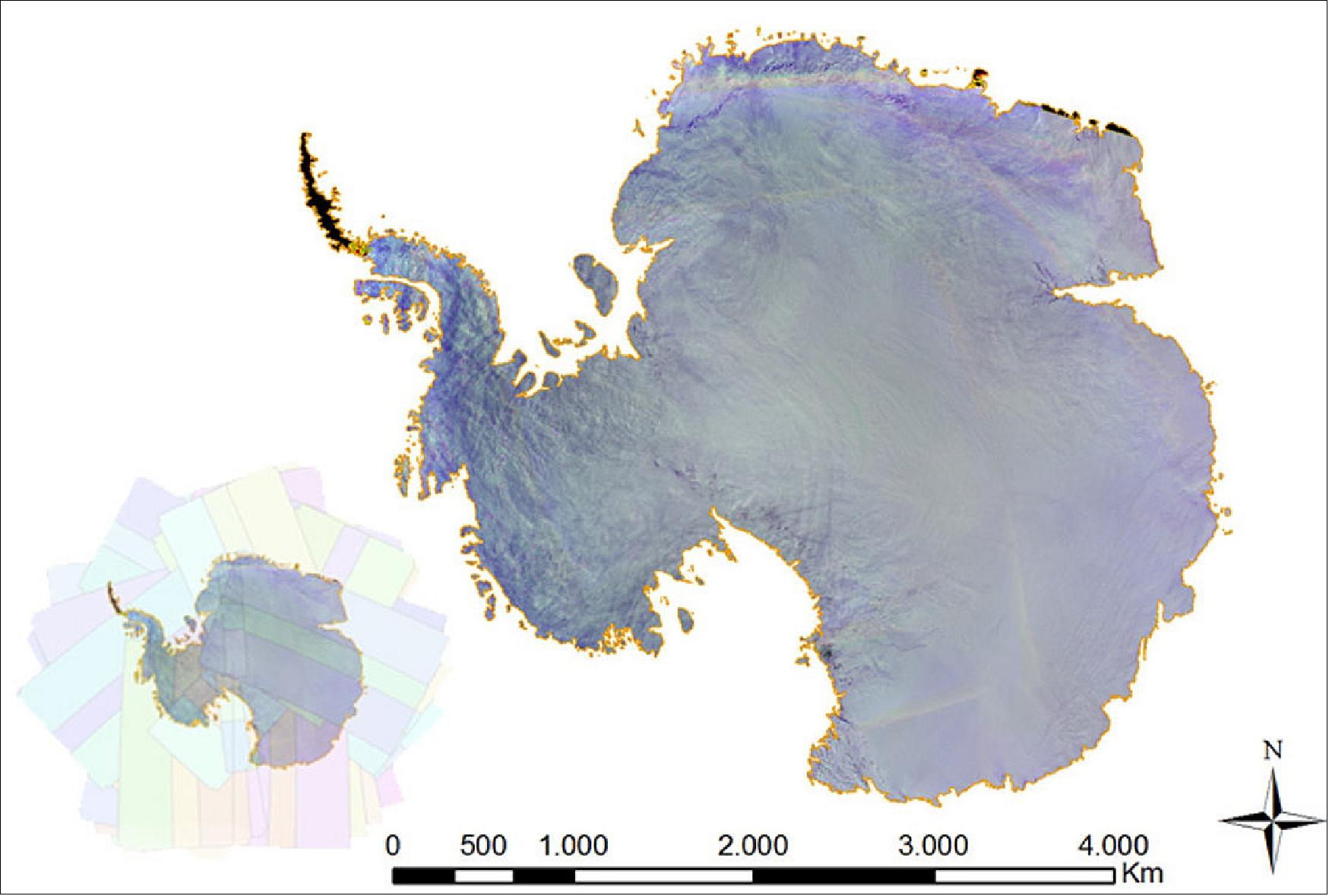
• May 04, 2018: ESA's Proba-V minisatellite has imaged all of the Antarctic after users asked for a survey of the icy southern continent. Proba-V collected the data between November 2017 and February 2018. 49)
- Imagery is available at 1 km, 300 m and 100 m resolution. For information on how to access it, click here. VITO Remote Sensing in Belgium processes and then distributes Proba-V data to users worldwide.
- On 7 May, 2018, PROBA-V will be 5 years on orbit. A PROBA-V symposium will be held in Ostend, Belgium (29-31 May, 2018) to bring researchers together to discuss the work being performed using the minisatellite.
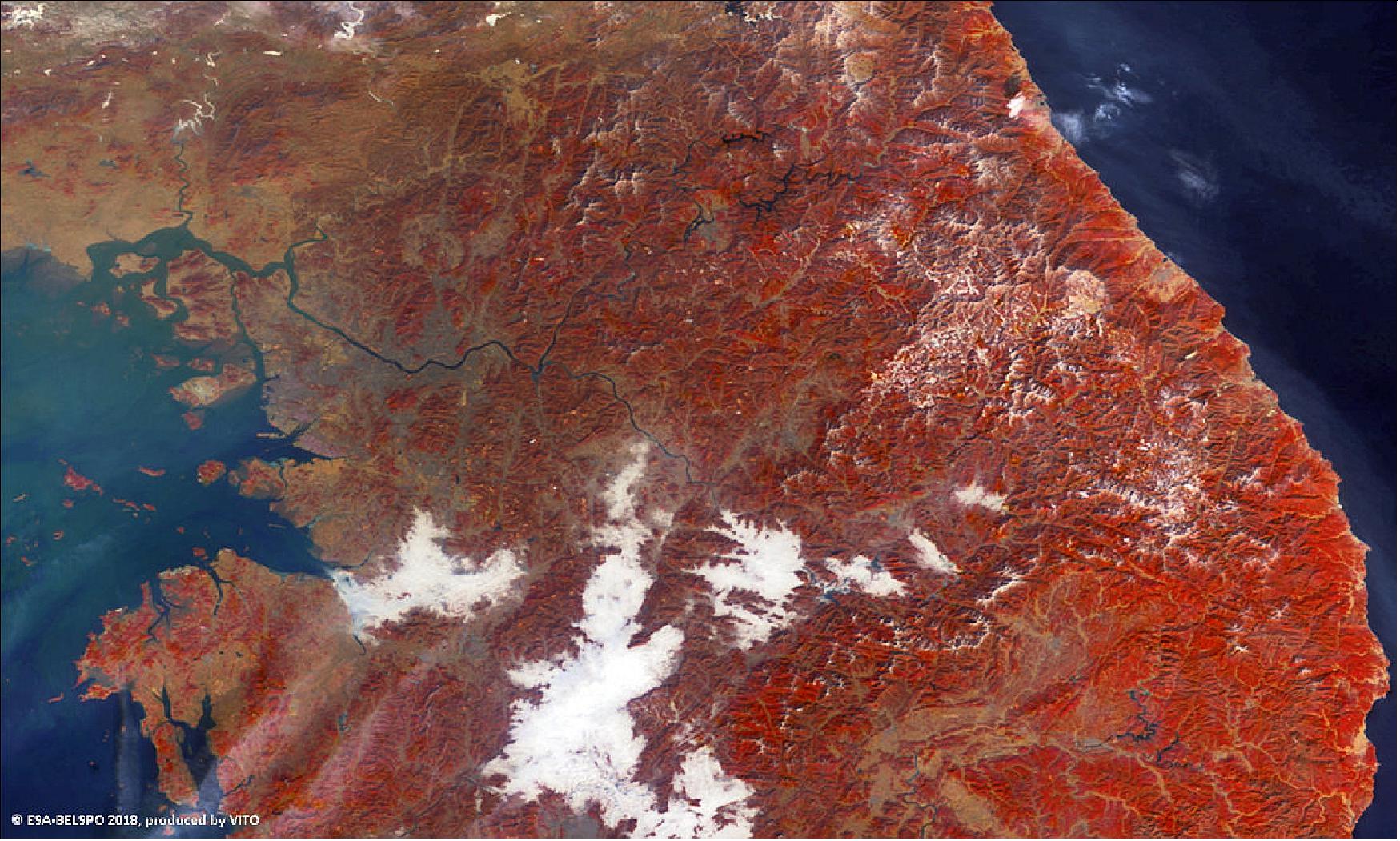
• February 14, 2018: Figure 30 is a false-color image of Pyeongchang county and surrounding territory in South Korea – currently hosting the 2018 Winter Olympics. This is a view of the northern part of the country, with vegetation in red and built-up areas seen in grey, including capital city Seoul, astride the banks of the Hangang River, seen left. Pyeongchang county is located towards the east coast. Mountainous regions are seen dusted with snow. 50)
- The Winter Olympics run from 8 to 25 February. By adding four new disciplines, this international event is the first Winter Games to extend over 100 medals, spread across 15 sports.
- PROBA-V's main camera's continent-spanning 2250 km swath width collects light in the blue, red, near-infrared and mid-infrared wavebands at 300 m resolution and down to 100 m resolution in its central field of view.
- VITO Remote Sensing in Belgium processes and then distributes PROBA-V data to users worldwide. An online image gallery highlights some of the mission's most striking images so far, including views of storms, fires and deforestation.
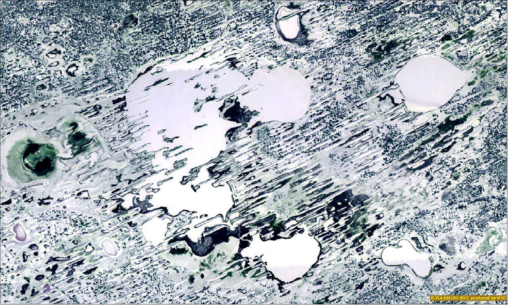
• December 20, 2017: Russia's frozen Lake Chany dusted by snow was captured by ESA's PROBA-V Earth-observing minisatellite (Figure 31). 51)
- Located just north of the border with Kazakhstan, Lake Chany is a large but shallow freshwater lake surrounded by wetlands, salt marshes and birch and aspen forests, making it an important stop for birds migrating southwards from colder Siberia.
- VITO Remote Sensing in Belgium processes and then distributes PROBA-V data to users worldwide. An online image gallery highlights some of the mission's most striking images so far, including views of storms, fires and deforestation.
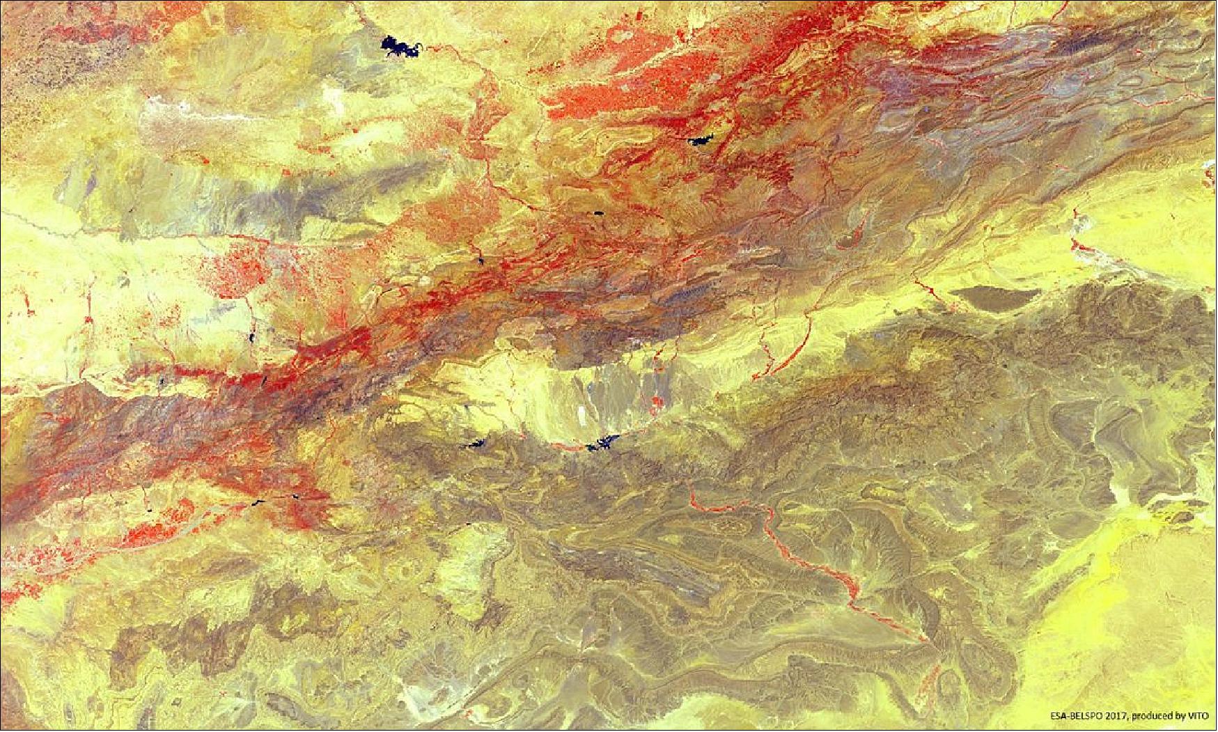
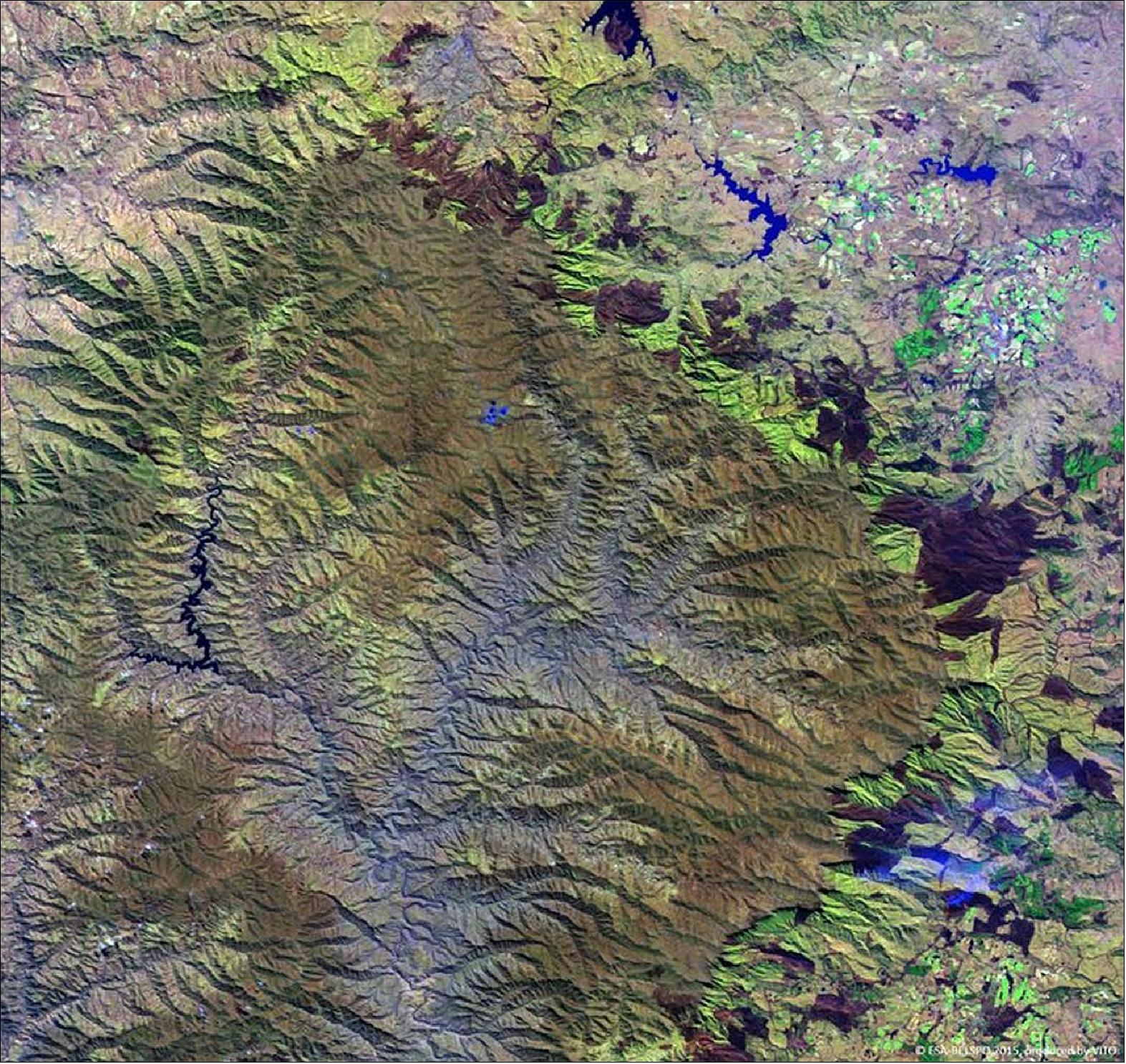
• November 10, 2017: North Africa's High Atlas mountain range was imaged by ESA's PROBA-V minisatellite last summer, with vegetation shown in false-color red (Figure 33). 52)
- The mountains – an extension of Europe's Alpine system – stretch some 2400 km through Morocco, seen here, into Algeria and Tunisia. The Atlas mountains are actually a set of five ranges dividing the northern Mediterranean climate from the arid Sahara to the south. A second, darker, range, the Anti-Atlas mountains, are seen to the south, with the the Draa River valley cutting through them – seen as a reddish line. The Draa, Morocco's longest river, flows south from the city of Ouarzazate city into the Sahara.
- The Berber-speaking Ouarzazate is a popular location for filmmakers, with productions such as Lawrence of Arabia (1962), The Mummy (1999) and Game of Thrones (2011–present) having been shot here.
- VITO Remote Sensing in Belgium processes and then distributes PROBA-V data to users worldwide. An online image gallery highlights some of the mission's most striking images so far, including views of storms, fires and deforestation.
• September 20, 2017: PROBA-V captures Bolivia's Salar de Uyuni, the world's largest salt plain – its 10,500 km2 make it larger than some countries. Located in the highlands of southwestern Bolivia at an altitude of 3650 m, Salar de Uyuni is also extremely flat, varying less than 1 m across its expanse (Figure 34). It is so flat that it is often used to calibrate laser and radar altimeters on satellites. 53)
- The salt plains were formed 42 000–30 000 years ago as a result of transformations between several prehistoric lakes. The crusty top layer, several meters thick in places, lies on a brine rich in lithium (containing 50–70% of the world's reserves), potassium and magnesium.

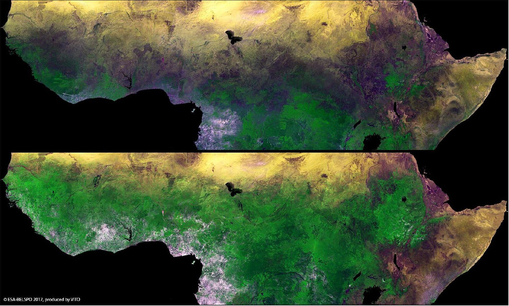
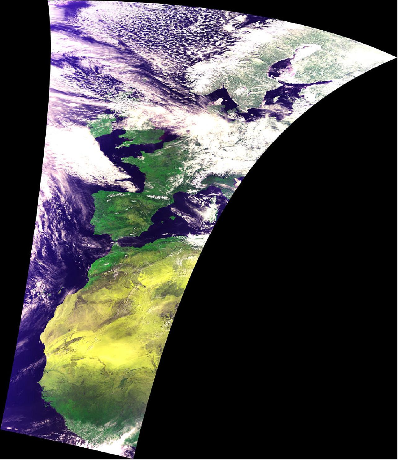
• July 27, 2017: ESA's Proba-V minisatellite reveals the seasonal changes in Africa's sub-Saharan Sahel, with the rainy season allowing vegetation to blossom between February (Figure 35 top) and September (bottom). 54)
- The semi-arid Sahel stretches more than 5000 km across Africa, from the Atlantic Ocean (Senegal, Mauritania) to the Red Sea (Sudan). The few months of the rainy season in the Sahel are much needed in these hot and sunny parts of Africa, and are critical for the food security and livelihood of their inhabitants.
- The name Sahel can be translated from Arabic as coast or shore, considered as the ever-shifting landward ‘coastline' of the arid Sahara Desert.

• June 21, 2017: ESA's PROBA-V minisatellite has captured the forest fire raging in central Portugal, revealing blackened scars and columns of smoke as well as pinpointing active fire hotspots. More than a thousand firefighters are tackling the forest fire in the Pedrógão Grande region, north east of Lisbon, which has been aflame since Saturday. Some 64 people have been reported dead and more than 130 injured. 55)
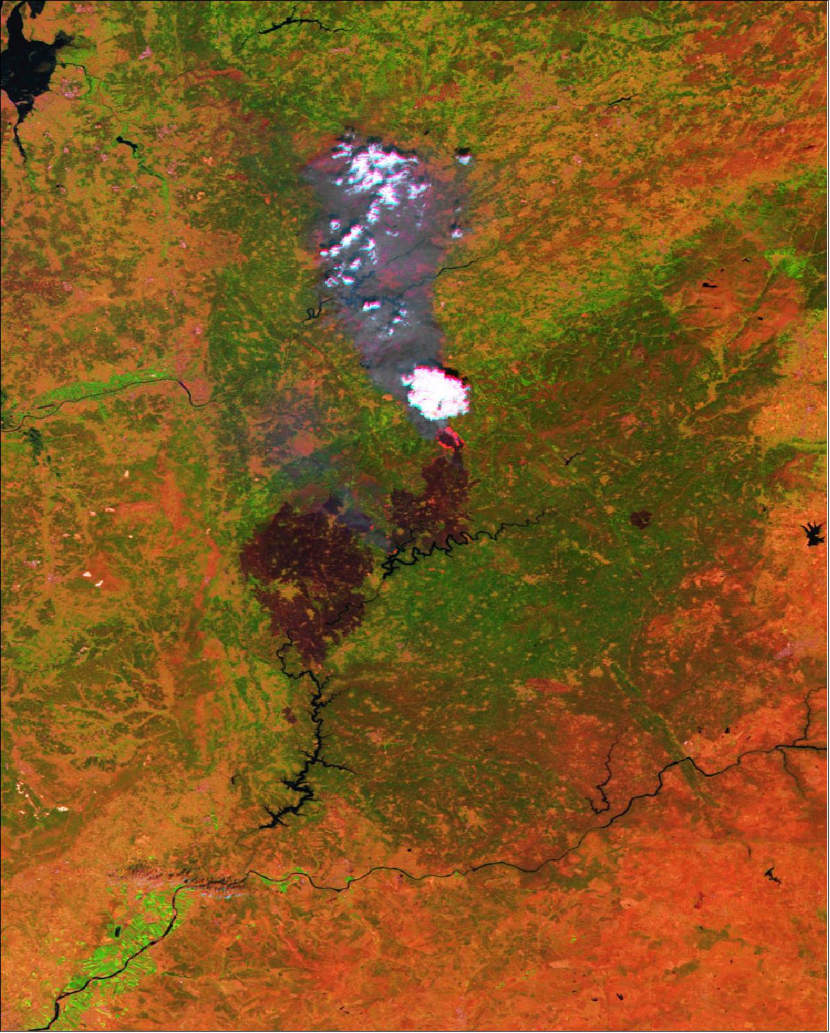
- PROBA-V has a 2250 km-wide field of view with an overall 300 m resolution, narrowing to 100 m at the center. The satellite contributes to Europe's world-monitoring Copernicus program, which makes imagery and data freely available to authorities. The V stands for Vegetation – a lighter but fully functional redesign of the camera previously flown on France's full-sized Spot-4 and Spot-5 satellites.
- Launched on 7 May 2013, PROBA-V continues the supply of this much-needed information for applications such as assessing climate impact, managing water resources and monitoring crops.
- PROBA-V's wide view and polar orbit means it revisits every spot on Earth's land every two days, building up a new global composite for researchers every 10 days.
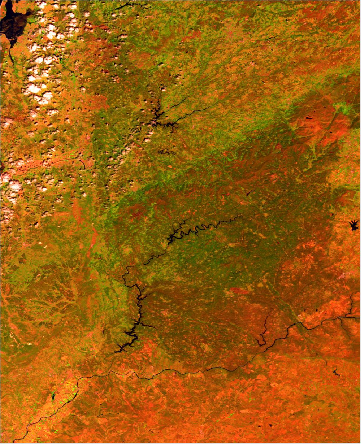
- The dammed Zêzere river is seen in the center of the main image, with burnt scars and fires burning to its north. The village of Nodeirinho – home of many of the casualties – is situated amid the scars.
- The forest fire is believed to have been started by a lightning strike during an intense heatwave. Aircraft have been used to drop water over the Pedrógão Grande region.
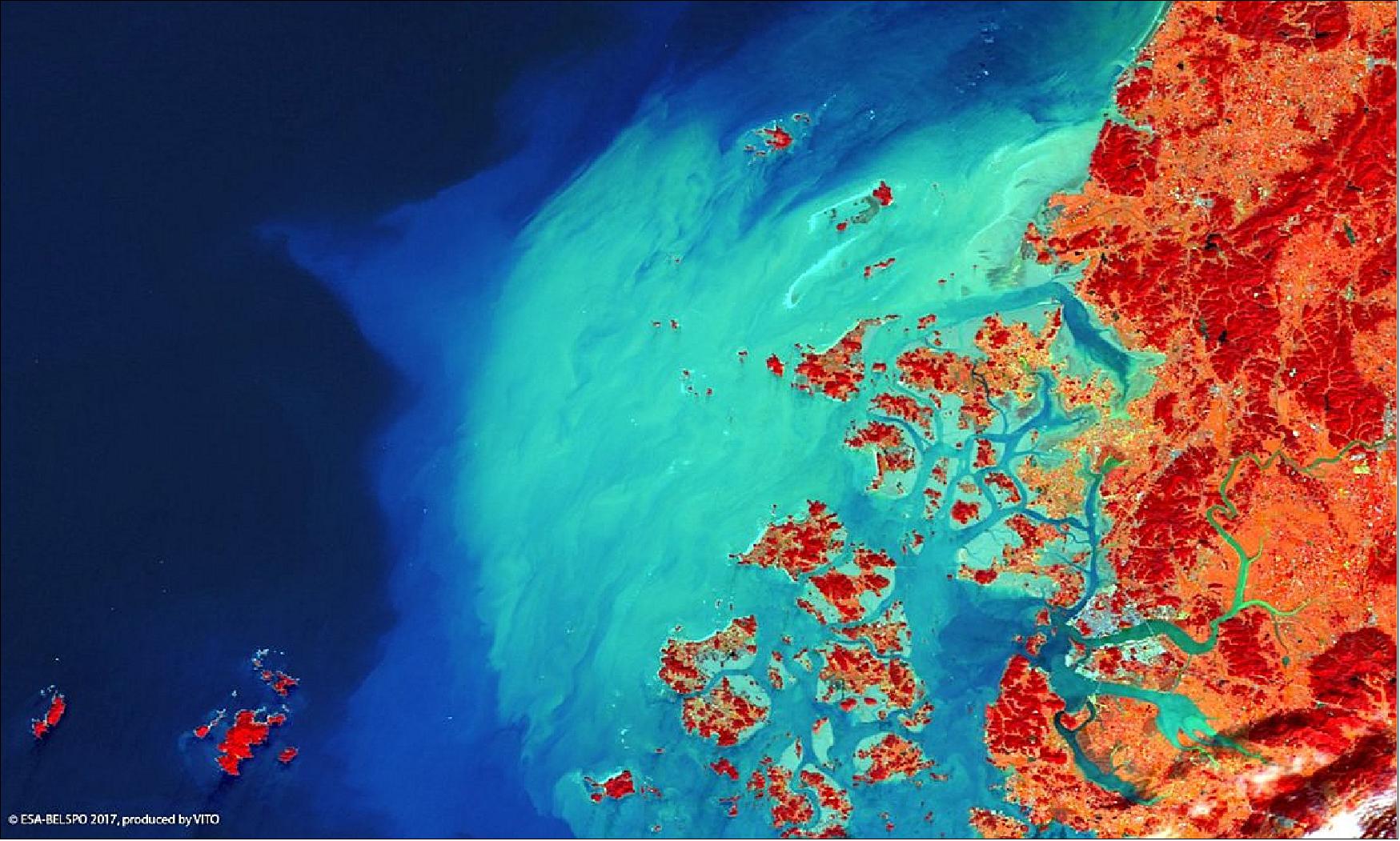
• May 19, 2017: The Korean the mid-sized city of Mokpo (~250,000 inhabitants) is a historic naval base and gateway to the country's Honam Plain. Mokpo is visible in this false-color image as a blue–grey area on the estuary of the Yeonsang River (Figure 39). The port city is surrounded by more than 1,400 islands, which provide fishing grounds while safeguarding Mokpo from the effects of large typhoons and tsunamis. An extensive region of high sediment concentrations is also visible, extending into the Yellow Sea in a bow shape. 56)
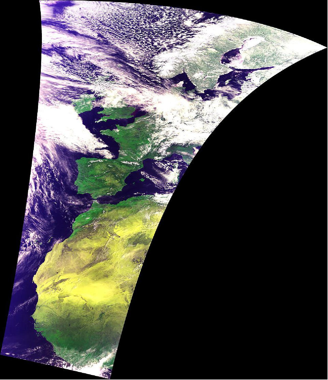
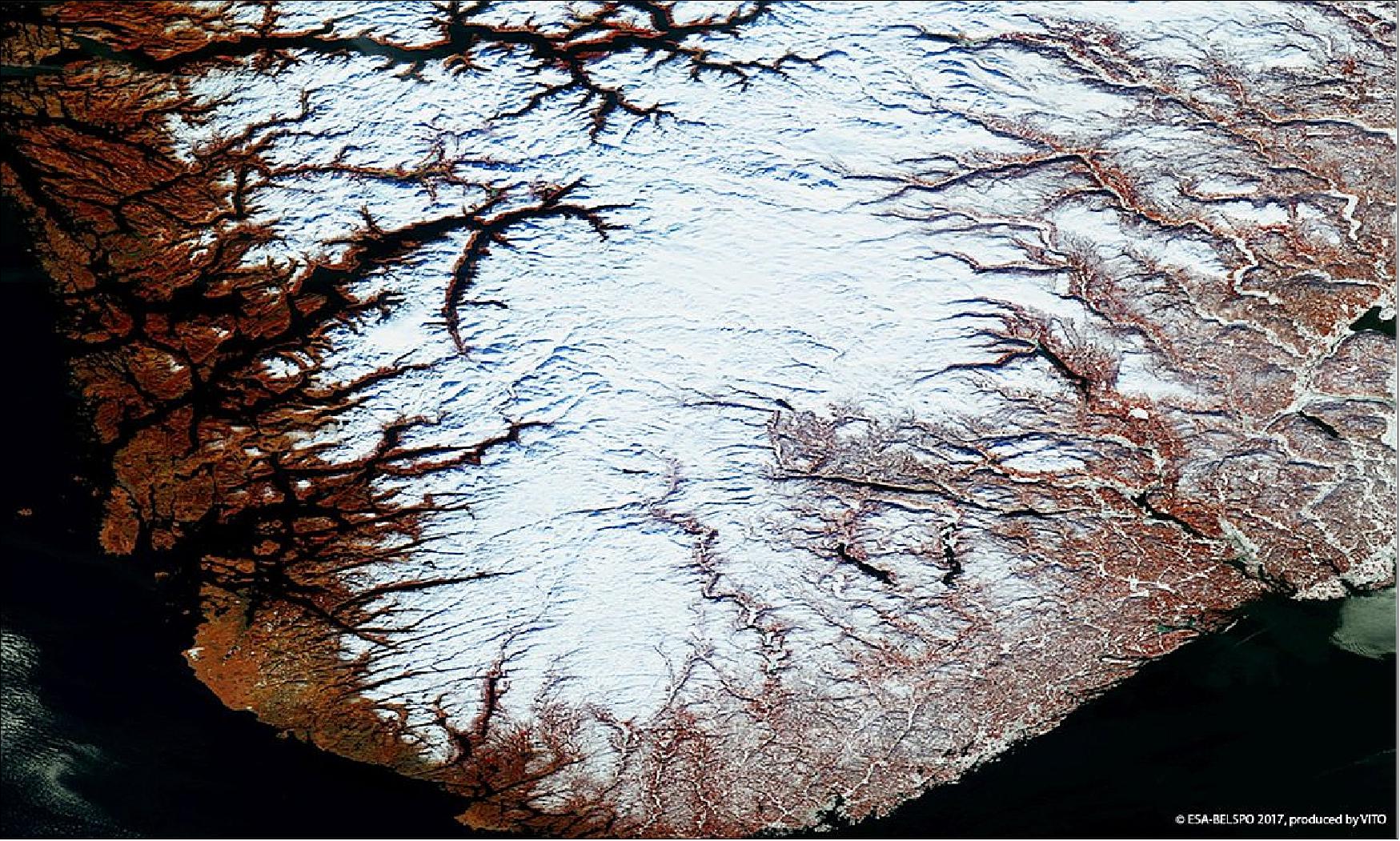
• March 29, 2017: Snow-dusted Norwegian fjords imaged by ESA's Earth-observing PROBA-V minisatellite. Norway's coastline is one of the world's longest – with a total length recently calculated at 80 000–100 000 km – owing to its famous fjords, narrow inlets bordered by steep cliffs created by glacial erosion during previous Ice Ages. 57)
- After these glaciers melted and Earth's crust rebounded, seawater flooded the valleys, leading to some fjords becoming very deep: the Sognefjord fjord (visible to the upper left) has a depth of 1300 m. From bottom to top the Bokna and Hardanger fjords are also seen. The white region in the middle is the Hardangervidda National Park, an extensive plateau at around 1200 m altitude, inhabited by wild reindeer.
- VITO Remote Sensing in Belgium processes and then distributes PROBA-V data to users worldwide. An online image gallery highlights some of the mission's most striking images so far, including views of storms, fires and deforestation.
• The PROBA-V minisatellite of ESA with the vegetation instrument on board is fully operational in February 2017. — The VITO processing center in Belgium provided the image of the week (Figure 41) with the Flinders Ranges in Australia. 58)
- The high plateau of the Gammon Ranges on the eastern side and the alternating hills and ridges, often with a gentle slope on one side and steep slope on the other (cuesta landforms), make for a dramatic and beautiful landscape.
- The region has a semi-arid climate with hot dry summers and cool winters. It's a place rich in Aboriginal history and home to a vast array of wildlife such as kangaroos, parrots, emus and snakes. The flora is well adapted to this environment, with species such as cypress-pine, black oak and mallee, a low-growing, bush-like eucalyptus that is common in Australia.

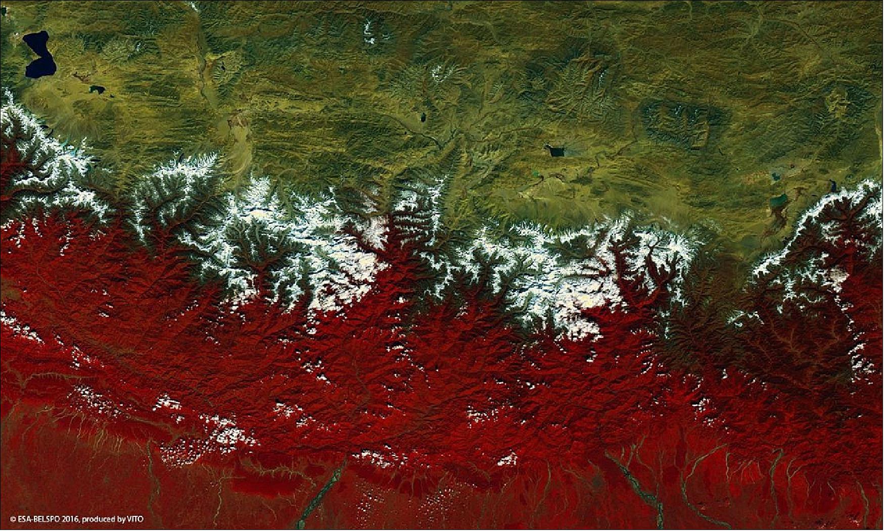
• December 15, 2016: In honor of the UN "World Mountain Day" on 11 December, the image of Figure 42 depicts the snow-capped Himalayas, with Nepal to the south (with vegetation shown in red) and the bleaker Tibetan Plateau to the north. 59)
- Mount Everest, the tallest mountain of the world at 8848 m, is shown in white along with a few of its 8000 m-plus neighbors, including Kangchenjunga (8586 m), the third tallest mountain of the world, to the east of Everest. The Himalayas, which can be translated from Sanskrit as ‘abode of snow', are the source of many major Asian rivers.
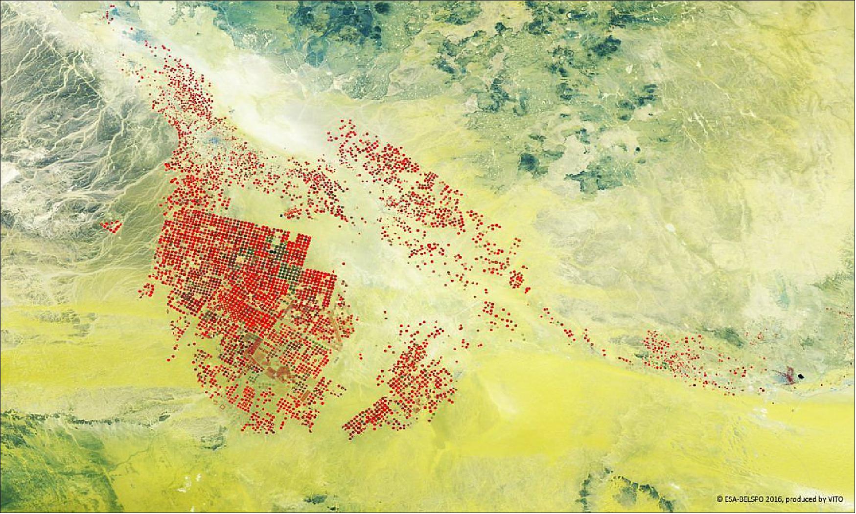
• October 19, 2016: ESA's PROBA-V minisatellite gives a false-color view of circular fields fed by underground water resource in the mist of the desert. This 100 m resolution image Figure 43) shows the Wadi As Sirhan basin of Saudi Arabia, with agricultural fields fed water by circular-pivot irrigation systems, amid the yellowish desert sands and surrounding low hills and rocks. 60)
- The VGT-P (Vegetation Instrument - PROBA) camera has a swath width of 2250 km, collecting light in the blue, red, near-infrared and mid-infrared wavebands at 300 m resolution and down to 100 m resolution in its central field of view.
• August 2016: The compact SATRAM (Space Application of Timepix-based Radiation Monitor) is operating nominally in LEO orbit since 2013 on board the PROBA-V satellite and provides high-resolution wide-range radiation monitoring of the satellite environment. Equipped with the pixel detector Timepix, the technology demonstration payload determines the composition (particle types) and spectral characterization (stopping power) of the mixed radiation field with quantum imaging sensitivity, charged particle tracking, energy loss and directionality capability. The space radiation field is continuously sampled over the entire planet every few days. Results are given in the form of spatial- and time-correlated maps of dose rate and particle flux. 61)
- Preliminary exploitation of data from the SATRAM/Timepix payload serves for detailed radiation effects studies but also for physics research and space weather studies.
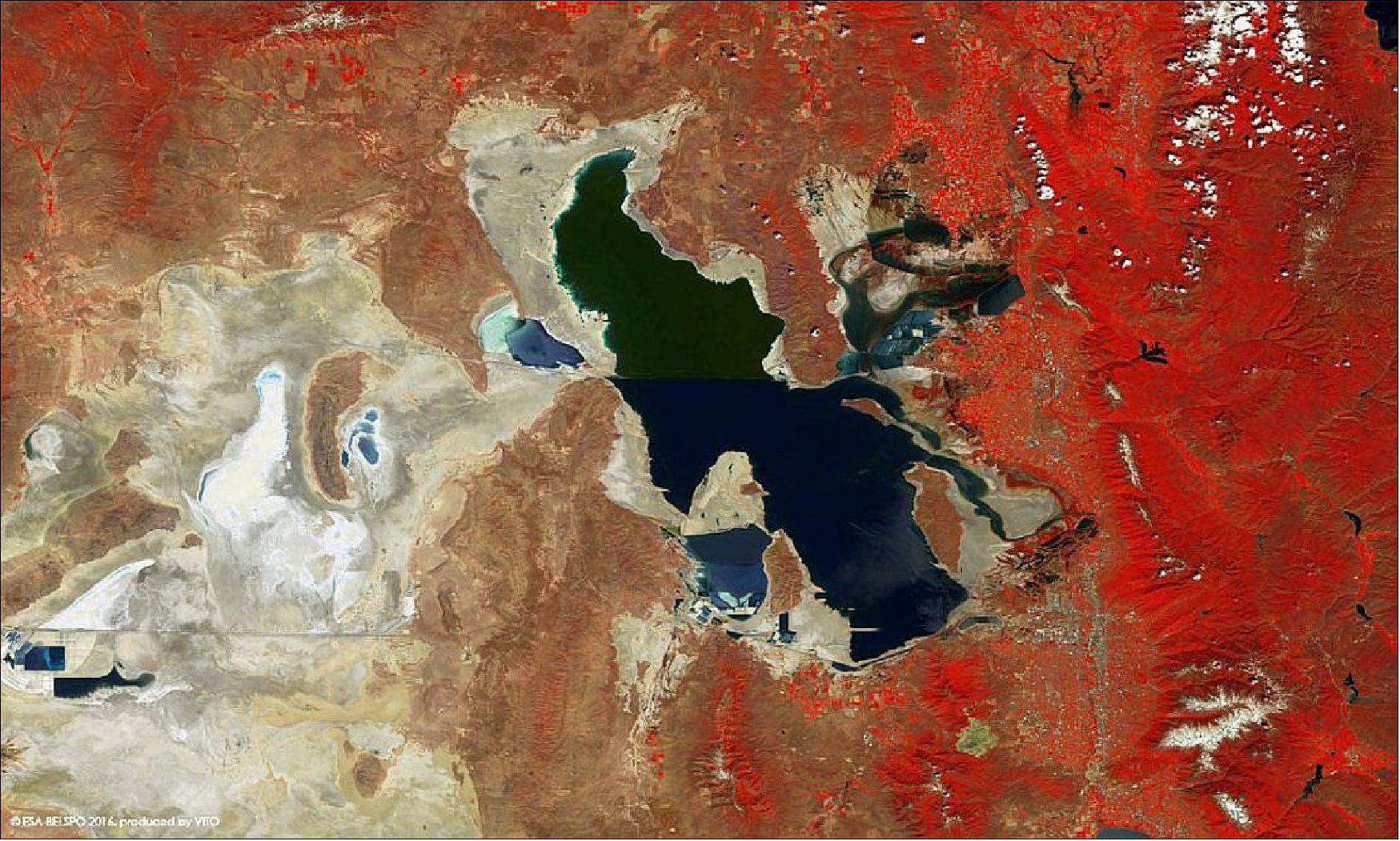
• August 26, 2016: ESA released a PROBA-V image of the Great Salt Lake in Utah, USA (Figure 44). The VGT-P instrumentation of the minisatellite provides a swath width of 2250 km in the blue, red, near-infrared and mid-infrared wavebands at 300 m resolution and down to 100 m resolution in its central field of view. 62)
• April 6, 2016: ESA's PROBA-V minisatellite gazes down at Earth's largest volcano – Mauna Loa, or ‘long mountain' which covers half of the island of Hawaii (Figure 45). Mauna Loa remains active, having last erupted in 1984. To the north of its distinctive blackened ridges is the still-higher Mauna Kea volcano – an extinct volcano whose crests are home to some of the world's leading astronomical observatories. 63)
- To its east is the very active Kilauea volcano, which has been erupting for more than three decades, the Hawaii Island being formed of five volcanoes altogether. The island's forest reserves are shown in green.
- Mauna Loa stands 4169 m above sea level, and extends another 5 km beneath the sea. Its 75,000 km3 volume depresses the adjacent sea bed another 6 km or so. This PROBA-V image was acquired on 19 February, 2016 with a resolution of 100 m. - VITO Remote Sensing in Belgium processes and then distributes PROBA-V data to users worldwide.

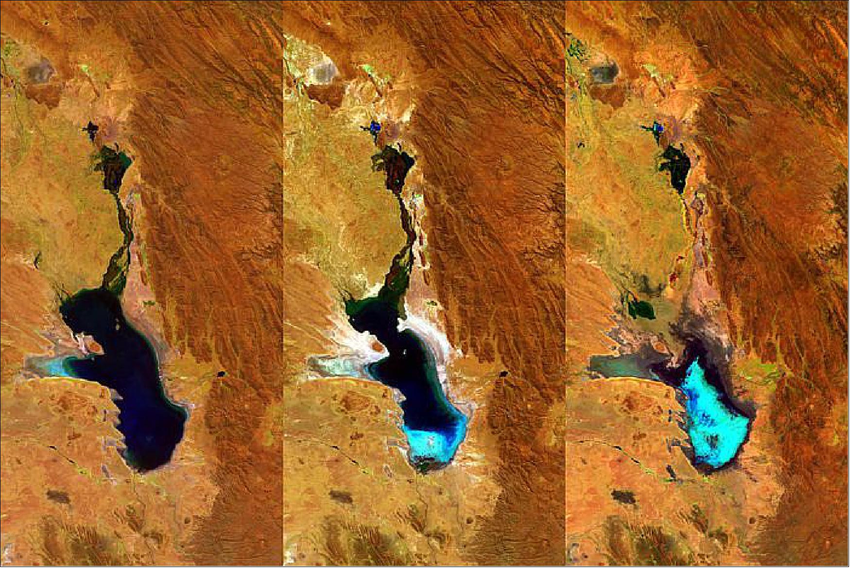
• February 8, 2016: Monitoring Earth's surface every day, ESA's PROBA-V minisatellite has had a ringside seat as the second largest lake in Bolivia, Lake Poopó, gradually dried up. Lake Poopó has now been declared fully evaporated. Occupying a depression in the Altiplano mountains, the saline Lake Poopó has in the past spanned an area of 3000 km2 — greater than France's Réunion Island. 64)
- But the lake's shallow nature, with an average depth of just 3 m, coupled with its arid highland surroundings, means that it is very sensitive to fluctuations in climate. Its official evaporation was declared last December. This is not the first time Lake Poopó has evaporated – the last time was in 1994 – but the fear is that any refilling might take many years, if it occurs at all.
- In the meantime local fishermen are left without livelihoods and the lake ecosystem is extremely vulnerable – Lake Poopó being recognized as a conservation wetland through the international Ramsar Convention.
- The evaporation has been variously linked to diversions of the lake's water sources for mining and agriculture, a persistent drought linked to El Niño warming in the Pacific Ocean and climate change.
• January 25, 2016: The PROBA-V minisatellite collected imagery in early 2016 of a large smoke plume from a bushfire south of Perth in Western Australia. Bushfires are frequent events during the long, dry Australian summer. In this fire, several hundred houses and an area exceeding 700 km2 have burned. Bushfires in the area are responsible for two deaths so far in 2016. Particularly hard hit was the town of Yarloop, which lost factories, a fire station, part of a local school and the heritage-listed Yarloop Timber Mill Workshops, which had been the most-intact example of a historical railway workshop in Australia. 66)

• January 2016: The PROBA-V mission has a nominal lifetime of 2.5 years; in 2015 the mission life was extended to 5 years. 67)
- Platform availability 99.9%; No safe mode in the last 12 months, all platform subsystems are nominal; Thermal situation very stable
- LTDN well within 10:30 – 11:30 hours; LTDN reaches 10:30 around Sept 2017; Stays well above 10:00 after 5 years.
- X-band data downlink DRS status: reliable!
1) Contract with SSC for the acquisition of PROBA-V X-band data at 3 stations: Kiruna (Sweden), North Pole (USA - Alaska) and Inuvik (Canada), allowing the PROBA-V reception of 10-11 passes per day
2) Acquisition performances are very good (in December over 315 passes acquired, only 4 had small data gaps = 99%); however rare delays in the data transfer from Inuvik
3) The Inuvik station will be upgraded with a fiber connection to the Canadian backbone during 2016, in order to improve the data transfer performances.
- PROBA-V Archive + Dissemination Status: Current PROBA-V Archive: 465 TB, with Disaster recovery: 930 TB; Total size of downloaded products: 252 TB.
• Dec. 15, 2015: ESA is pleased to announce that accessing PROBA-V data is easier than ever (and always free): 68)
- All level 1C (NRT), all 1 km products (NRT), and all 333 m and 100 m products (older than 1 month) can be downloaded immediately after registration to the PROBA-V portal.
- All 333 m and 100 m in NRT (Near Real Time) are also offered to ESA PIs by ESA (free of charge). Access is granted after ESA project proposal acceptance (proposal submission), see the PROBA-V Information Area on Earth
• October 21, 2015: Figure 48 presents a view of the glacier atop Africa's highest peak, as observed by ESA's PROBA-V minisatellite. The dormant volcano known as Mount Kilimanjaro is Africa's highest mountain, at 5895 m above sea level. It is also the tallest free-standing mountain in the world, rising about 4900 m above its surrounding plain. 69)
- Located close to the equator at 3ºS in Tanzania, only its summit is covered with snow and ice. The ascent towards the top is a journey through most of the world's climate zones, from the tropical to the Arctic. On the way the landscape shifts from tropical rain forest to moorland, alpine heather to desert and finally snow and ice. - The mountain is part of the Kilimanjaro National Park and is a major climbing destination. The mountain has been the subject of many scientific studies because of its shrinking glaciers.

• August 2015: PROBA-V provides continuation of SPOT-Vegetation (SPOT-VGT) products in its 4 bands: Blue, Red, NIR and SWIR. Aside from the global daily 1 km time series available from SPOT-VGT since 1998, PROBA-V brings new assets with a global daily 300 m time series for the same set of bands. In addition, 100 m products are available from March 16 2014, delivering a global coverage every 5 days. 70)
- The VGT-P (Vegetation-PROBA) instrument has several specific properties influencing its products : 1) VNIR and SWIR detectors mounted on different locations; 2) VNIR and SWIR with different GSD; 3) mechanically staggered SWIR detector composed by three overlapping detectors with an overlap area.
- Like SPOT-VGT, PROBA-V's spectral bands allow to discriminate between different types of land cover and land use, in particular plant species and crops, often measured by derived products such as the NDVI (Normalized Difference Vegetation Index). Vital uses of these data include day-by-day tracking of vegetation growth, early warnings to authorities of crop failures, monitoring of inland water resources and tracing trends of soil erosion and deforestation.
Product | Spatial and temporal resolution | Product class |
S10 TOC (Top of Canopy) 1 km | 1 km, every 10 days | Free, NRT (Near Real Time) |
S1 TOA (Top of Atmosphere)/TOC 1 km | 1 km, every day | Free, NRT |
S10 TOC 300 m | 300 m, every 10 days | Commercial, NRT; Free after 1 month |
S1 TOA/TOC 300 m | 300 m, every day | Commercial, NRT; Free after 1 month |
LIC(radiometrically and geometrically calibrated | Raw resolution, instantaneous | Commercial, NRT; Free after 1 month |
S1 TOA/TOC 100 m | 100 m, every day | Commercial, NRT; Free after 1 month |
S5 TOA/TOC 100 m | 100 m, every 5 days | Commercial, NRT; Free after 1 month |
Free products are always delivered in standard format and on best-effort basis. | ||
- Operational status: After more than a year of calibration monitoring, PROBA-V is able to show impressive results, showing a stable radiometric and geometric performance, and a consistency with missions such as SPOT-VGT, MERIS and Landsat-8. All performance requirements for the 1 km and 1/3 km products have been successfully achieved (Tables 9 and 10).
Geo-localization measurements | Accuracy for ⅓ km product (95 %) | Accuracy for 1 km product (95 %) |
Inter-band (VNIR) | 100 m |
|
Inter-band (SWIR + VNIR) | 150 m | 300 m |
Multi-temporal (VNIR) | 150 m |
|
Multi-temporal (SWIR + VNIR) | 225 m | 500 m |
Absolute (VNIR) | 300 m |
|
Absolute (SWIR + VNIR) | 450 m | 1000 m |
Radiometric measurements | Accuracy for all products (95 %) |
Inter-band | 3% |
Multi-temporal | 3% |
Absolute | 5% |
• On May 7, 2015, PROBA-V was two years on orbit, operating nominally. - As ESA's PROBA-V works quietly on its main task of monitoring vegetation growth across Earth, the minisatellite is also picking up something from a little higher: signals from thousands of aircraft.
- During its operational life, the PROBA-V minisatellite has picked up aircraft positions, using an experimental ADS-B (Automatic Dependent Surveillance – Broadcast) receiver (Figure 49). The ADS-B receiver was built by DLR. These signals are regularly broadcast from aircraft, giving flight information such as speed, position and altitude. All aircraft entering European airspace are envisaged to carry ADS-B in the coming years. 71)
- The ADS-B signals include GPS data on the aircraft's position, speed and altitude, and the signals are designed to be detected by ground stations and nearby airplanes. The 1500 x 750 km footprint of the single satellite is relatively small and a fully world-wide operational system would require a constellation of satellites. Several commercial operators have indicated interest in establishing such a system.
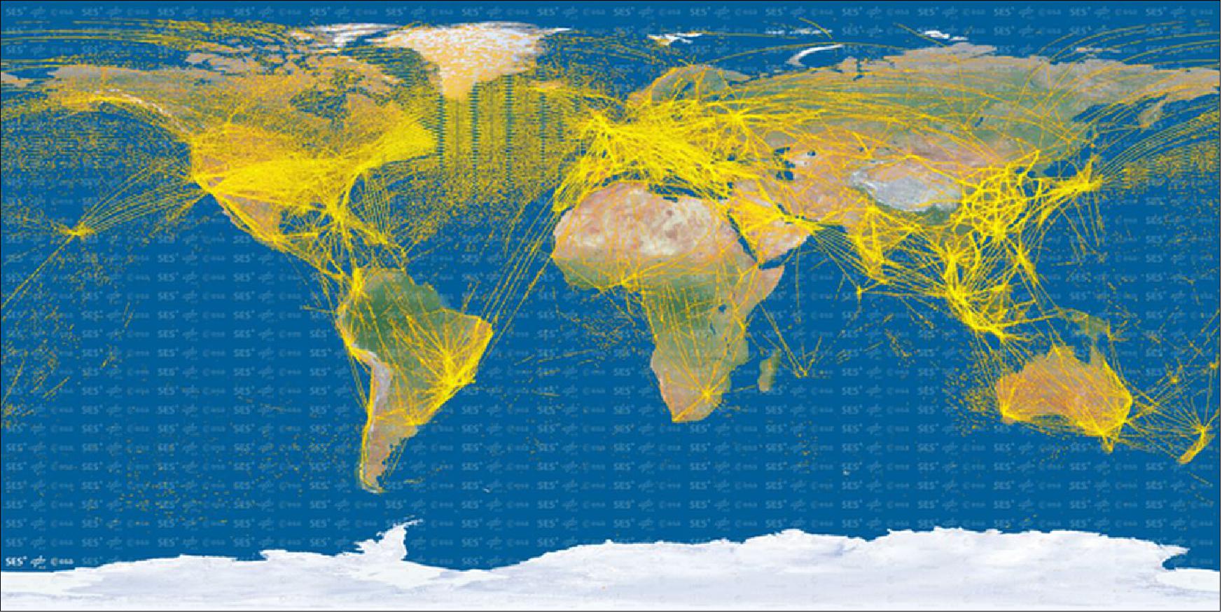
Legend to Figure 49: There are roughly 20 000 aircraft worldwide from which the DLR (German Aerospace Center) and the SES Techcom team has captured more than 25 million positions. The team has identified more than 22,000 unique callsigns, identifying more than 15,000 aircraft by their unique ICAO (International Civil Aviation Organization) addresses (one aircraft can share a callsign with others, depending on the flight route).
• May 6, 2015: The Drakensberg mountain range – Afrikaans for ‘Dragon mountains' – is located in southern Africa and extends from northeast to southwest for about 1125 km. This 100 m resolution image (Figure 50) centers on uKhahlamba–Drakensberg Park, located at Lesotho's northeastern border with the South African province of Kwazulu-Natal, covering roughly 240,000 hectares. Lesotho's Malibamats'o River is visible to the upper left. 72)
- Rich in its diversity of habitats, the park is home to various populations of endemic birds, mammals and reptiles. It is also home to the largest collection of rock paintings in Africa, south of the Sahara. The paintings reflect the way of life of the San people, who lived in the area for more than four millennia. In 2000, UNESCO named the park as a World Heritage Site.
• March 6, 2015: A high-speed camera for monitoring vegetation from space and combating famine in Africa is being adapted to spot changes in human skin cells, invisible to the naked eye, to help diagnose skin diseases like cancer. 73)
- In fact, the extraordinary digital infrared sensor from ESA's PROBA-V vegetation-scanning satellite is being adapted for several non-space applications. Mounted on a standard medical scanner, the space sensor can help doctors to look deeper into human tissues for detecting skin diseases earlier. It also has a bright future in industry: it has already been shown to improve solar cell production as well as spotting defective items on production lines.
- Leading-edge space technology: The PROBA-V camera has such a unique wide field of view that it allows the small satellite to build a fresh picture of our entire planet's flora every two days. Developed for ESA by the Belgian company Xenics, the camera sees light we cannot by looking in the shortwave infrared range.
- PROBA-V's ability to ‘see the unseeable' as Earth revolves beneath made the commercialization of the camera a natural step. With support from ESA and the Belgian Space Technology Transfer Program, the Xenics team created ‘Machine Vision', integrating cameras on inspection systems to replace humans in looking for imperfections. The high-speed resolution of our ‘line-scan' cameras makes them ideal for detecting hidden defects on fast-moving production lines, such as bottle manufacturing or sorting different types of plastics for recycling – all of which look similar to the human eye.
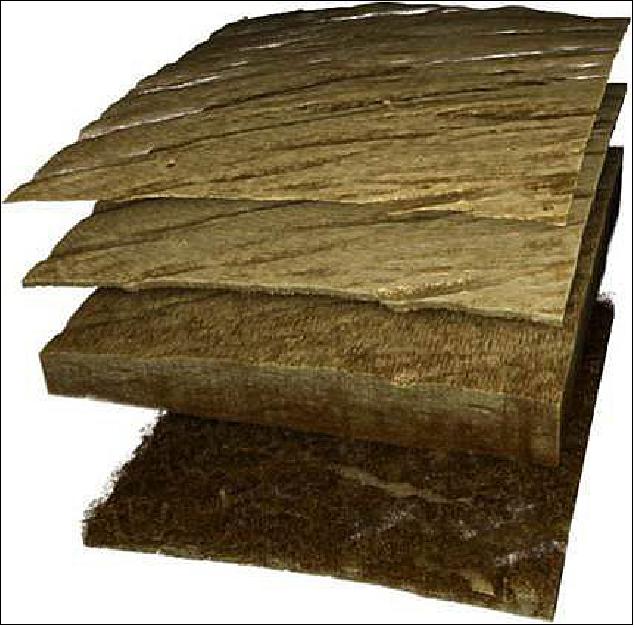
• On March 4, 2015, ESA released Figure 52 in which the PROBA-V minisatellite captured the rare sight of standing water in the arid south Australian outback. Lake Frome, one of the whitest salt lakes in the southern hemisphere is visible to the right. Unusually, this 12 February image shows it filled with brackish water from the surrounding creeks in the area, which are typically dry. - Covering most of this 100 m spatial resolution image are the ranges and gorges of Vulkathunha-Gammon Ranges National Park, haven to many rare and endangered plants and animals. 74)
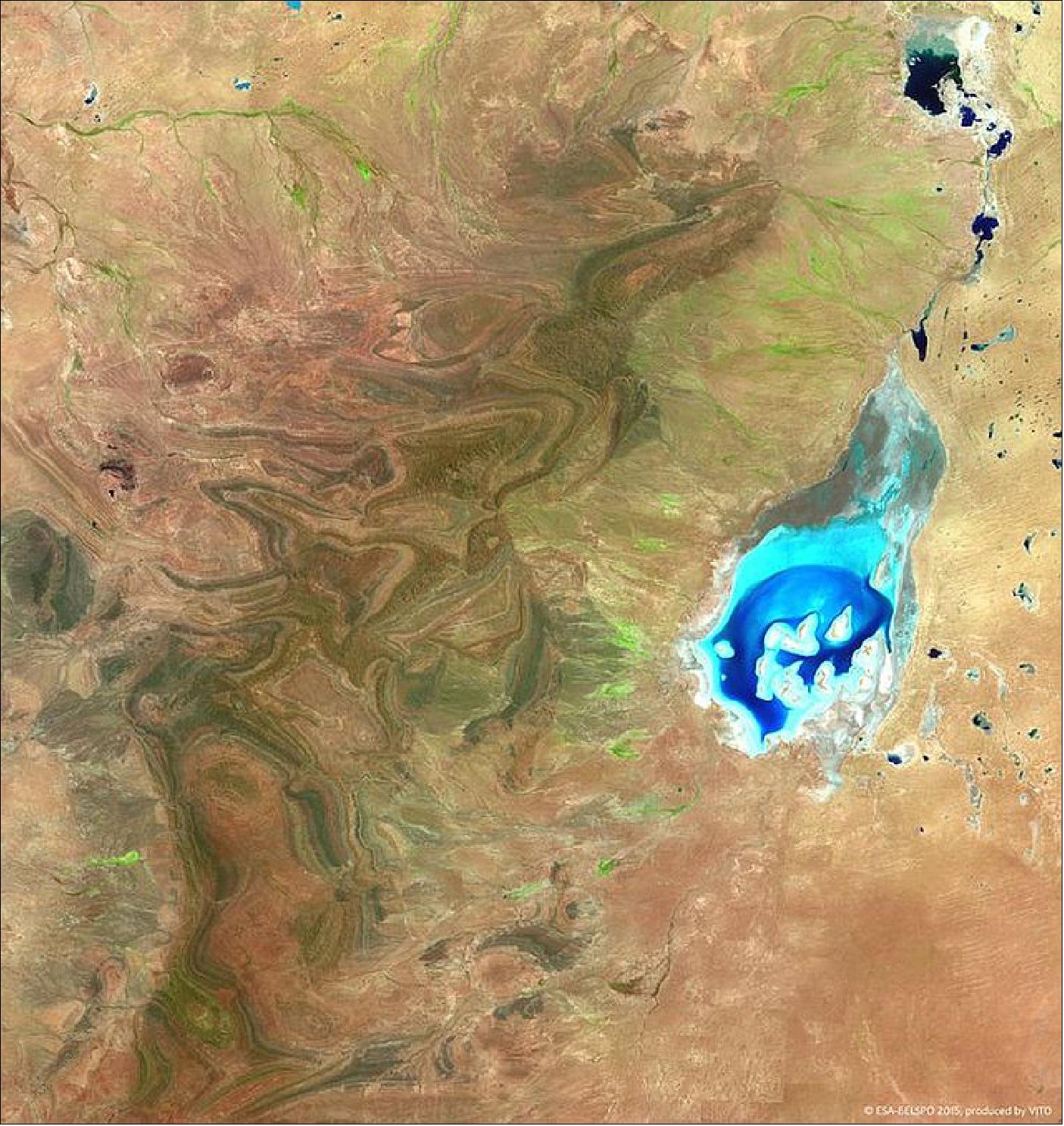
• Fall 2014: Study for PROBA-V Successor Mission: PROBA-V has been successfully launched on May 7,2013 and is providing a global monitoring in the continuity of the SPOT-VEGETATION mission. The progress in terms of ground resolution between Spot VGT and PROBA-V is a factor 3 (1 km to 300 m ground resolution product). The User Community requirements for the next generation of global monitoring call for a 100 m ground resolution product. This means an additional factor 3 improvement, but in a short time frame (5 years). After the success of the PROBA-V mission, the Belgian Science Policy (BELSPO) initiated a PROBA-V Successor feasibility study. This study was undertaken by VITO and CSL to identify potential tracks to achieve a follow-on mission which is expected to be relevant for the User Community. The mission analyses for each of these tracks was evaluated. Today the PROBA-V mission lifetime is expected to expire by mid of 2018. 75)
Since the interest for global land monitoring is expected to continue in the future, this study proposes mission requirements and a shortlist of optimal mission scenarios for a follow-on mission in this short time frame. The goal of such a new PROBA-V mission is clear: it should ensure the data continuity of global vegetation monitoring, while taking the opportunity to further improve the data quality. Data continuity is essential for understanding long term trends of land use that may affect the global equilibrium of the planet (in the context of scarcity for land or food, natural disasters, climate change). As for added value, a fine example is the improvement of spatial resolution when comparing PROBA-V with the spatial resolution in SPOT-VEGETATION products. An improvement in spatial resolution towards a full 100 m product is considered by the user community as the main target for a PROBA-V follow-on mission.
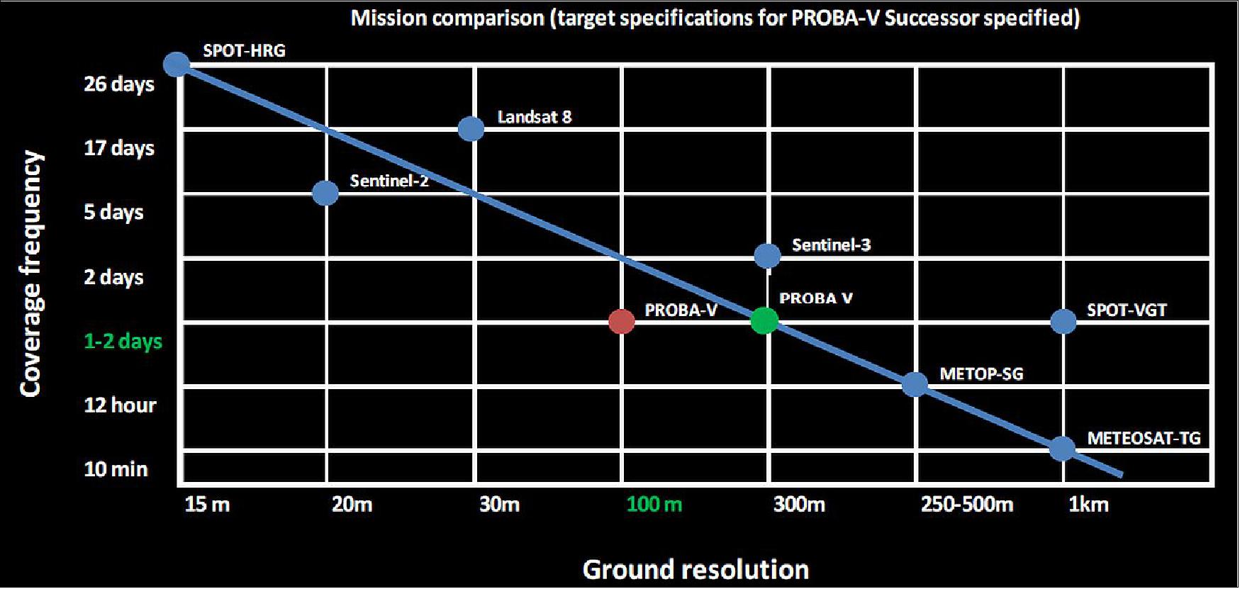
• Dec. 4, 2014: ESA released Figure 54 as 'image of the week': PROBA-V catches the Sangeang Api volcano on the island of Sangeang in Indonesia as a thick column of ash and sulphur dioxide pumps into the atmosphere. The dense ash grounded flights across much of the archipelago nation. 76)
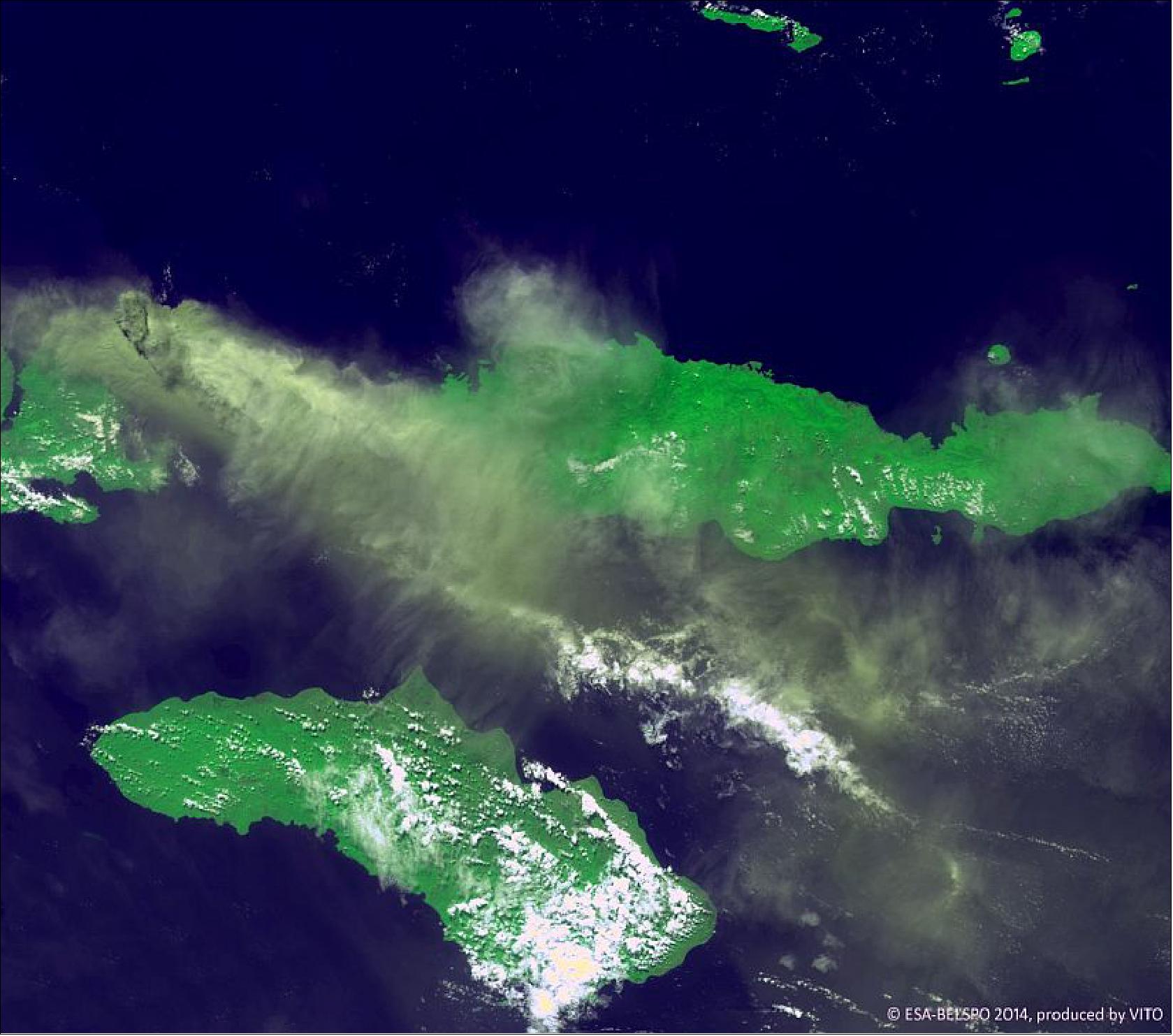
• The PROBA-V image (Figure 55) of western Brazil was released on October 16, 2014. This 300 m resolution image reveals the human impact on the world's largest tropical rainforest. The brownish colors indicate deforested areas – note the distinctive ‘fishbone' pattern as main roads are cut through an area, followed by secondary roads for further clearing. 77)
- INPE, the Brazilian Institute for Space Research, uses satellites to monitor Brazil's rainforests. Its results show the annual rate of deforestation has fallen from some 3900 km2 in 2004 to 900 km2 in 2013, although substantial amounts of precious forest are still disappearing every day.
- PROBA-V's images are processed and distributed to hundreds of scientific users by VITO, Belgium's Flemish Institute for Technological Research, extending the coverage of previous generations of the Vegetation camera flown on the SPOT-4 and SPOT-5 satellites.
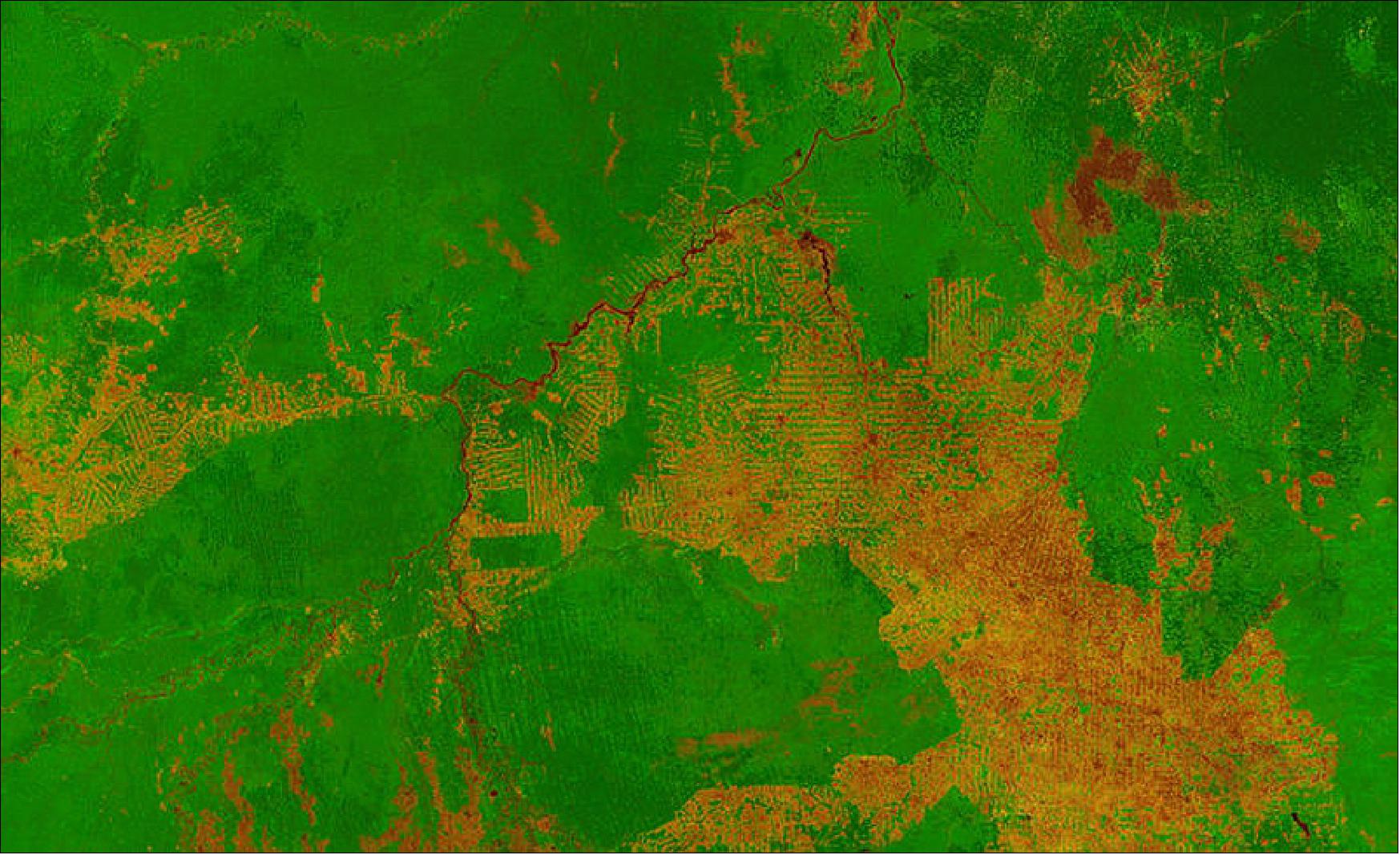
• The PROBA-V mission is operating nominally in August 2014. — For the annual Small Satellite Conference of AIAA/USU, Logan, UT, the PROBA-V project published a paper with the title: "PROBA-V: The example of onboard and onground autonomy," virtually the entire paper is presented in the last chapter of this file. It demonstrates vividly many autonomy concepts and aspects implemented successively for the PROBA series. The content might be of interest and value to the entire EO community.
• June 6, 2014: The SPOT Vegetation mission, flown on SPOT-4 and SPOT-5 for 16 years, marked 16 years of service in May, and has now passed the torch to its European counterpart. As of June 1, 2014, PROBA-V is the official successor mission — mapping land cover and vegetation growth across the entire planet every two days. The data can also be used for day-by-day tracking of extreme weather, alerting authorities to crop failures, monitoring inland water resources and tracing the steady spread of deserts and deforestation. 78)
- PROBA-V has demonstrated the benefit of the utilization of small satellites for an operational mission, as well as for the in-orbit demonstration of new technologies and technological payloads that can benefit from an early flight opportunity and quick implementation from decision to flight (Ref. 25). All embarked technological payloads are working properly and continuously on-board thanks to the allocation of the system resources that became available along with the project implementation. The flexibility of the PROBA platform and the integration process of the satellite has allowed to manifest even late flight opportunities for new technological payloads.- Due to the autonomous character of the flight and the ground segments, virtually all operational activities don't require human intervention, while keeping the availability of the system very high.

• Status of ADS-B in late May 2014: General aspects of the results. 79)
The ADS-B receiver on board the satellite was the first experiment of its kind, receiving 1090ES ADS-B squitter signals transmitted from aircraft. Therefore the experimenter could not build on experiences or any evaluation results. The assessment of the achieved results should take into account the constraints under which this experiment was realized, as there were limitations in cost and time but in particular available resources on the satellite in terms of available power and geometry.
The reception of 1090 Extended Squitter ADS-B messages on board of the PROBA-V satellite is mainly affected by the following issues, which may lead to a loss of ADS-B information:
- RF signal loss due to the low signal level resulting from the distance between the receiving satellite at an altitude of approximately 820 km and the transmitting aircraft at an altitude of 0 to 12 km.
- RF signal loss due to the shapes of the satellite antenna vertical radiation pattern and the aircraft antenna vertical radiation pattern.
- Corruption of messages by garbling, when several messages arriving at the ADS-B antenna onboard of the satellite at the same time overlap and thus cannot be decoded by the ADS-B receiver.
- Speed of the satellite of about 27000 km/h, which leads to a limited time of observation for each detected aircraft of about 3 minutes maximum (Ref. 79).
A separate file of ADS-B was added to the eoPortal in June 2014, providing more information of ADS-B (Automatic Dependent Surveillance-Broadcast) over Satellite.
• On May 31, 2014, the SPOT-Vegetation program will hand over the torch to the PROBA-V mission. 80)
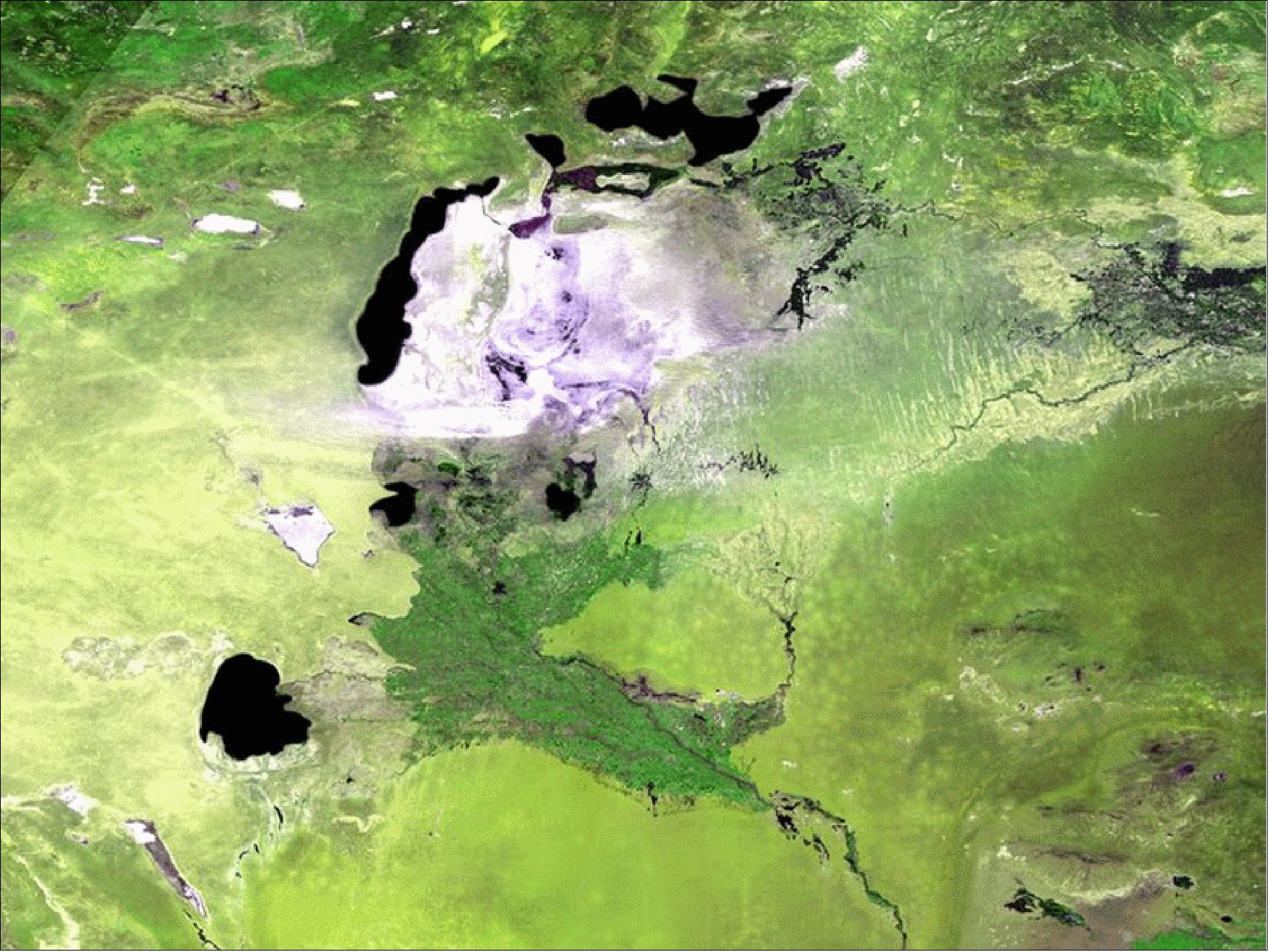
Legend to Figure 57: The Aral Sea is a striking example of the kind of changes the satellite series (SPOT-4, -5 and PROBA-V) with the Vegetation instrument has been tracking. Once the world's fourth-largest inland water body, it has lost around 90% of its water volume since 1960 because of Soviet-era irrigation schemes. The image depicts the white salt terrain left behind by the southern Aral Sea receding, now called the Aral Karakum Desert. The greenery to the south is cultivated land irrigated by the Amu Darya river.
Some background on the SPOT Vegetation program (Ref. 80)
The SPOT-Vegetation mission has been delivering images on the global vegetation status to more than 10,000 users worldwide on a daily basis. Now, 16 years later, it is time for SPOT-Vegetation to hand over the torch to its successor, the minisatellite PROBA- V(Vegetation) of ESA.
The SPOT-Vegetation mission is a collaboration between France, Belgium, Italy, Sweden and the EC that has been monitoring the global vegetation status for more than 16 years. The Vegetation instruments (VGT-1 and VGT-2) were incorporated in the SPOT program, a program that was founded in 1978.
SPOT-4, with VGT-1 on board, was launched on March 24,1998. The VGT-2 instrument, incorporated onto the SPOT-5 satellite, was sent into orbit on May 4, 2002. SPOT-4 has been deactivated a couple of years ago, but SPOT-5 will still be delivering images of the Earth until the end of May 2014. Every day a new image of the global vegetation status is being processed, archived and distributed at the Image Processing Center of VITO in Belgium.
As PROBA-V was launched one year before the end of Vegetation (on May 7, 2013), both missions had a nice and clean overlap of one year. This overlap is highly important to ensure cross-calibration between both missions which is necessary to guarantee a consistent time series.
In addition to this intent of continuation, there is also an important upgrade in spatial resolution from 1 km (SPOT-Vegetation) to 300 m (PROBA-V), allowing extraction of more detailed information on crop yields, droughts, desertification, changes in the type of vegetation, deforestation, etc. This higher spatial resolution is also in line with the upcoming Sentinel-3 mission, hereby offering users the prospect of an uninterrupted times series of 25 years or more.
• On May 7, 2014, the PROBA-V minisatellite was 1 year on orbit. For this occasion, ESA and VITO provided some recent imagery of the PROBA-V spacecraft (Figures 58, 59 and 60). — PROBA-V is set to make a giant leap for a minisatellite: formally taking over the task of continuously charting our planet's global vegetation. 82)
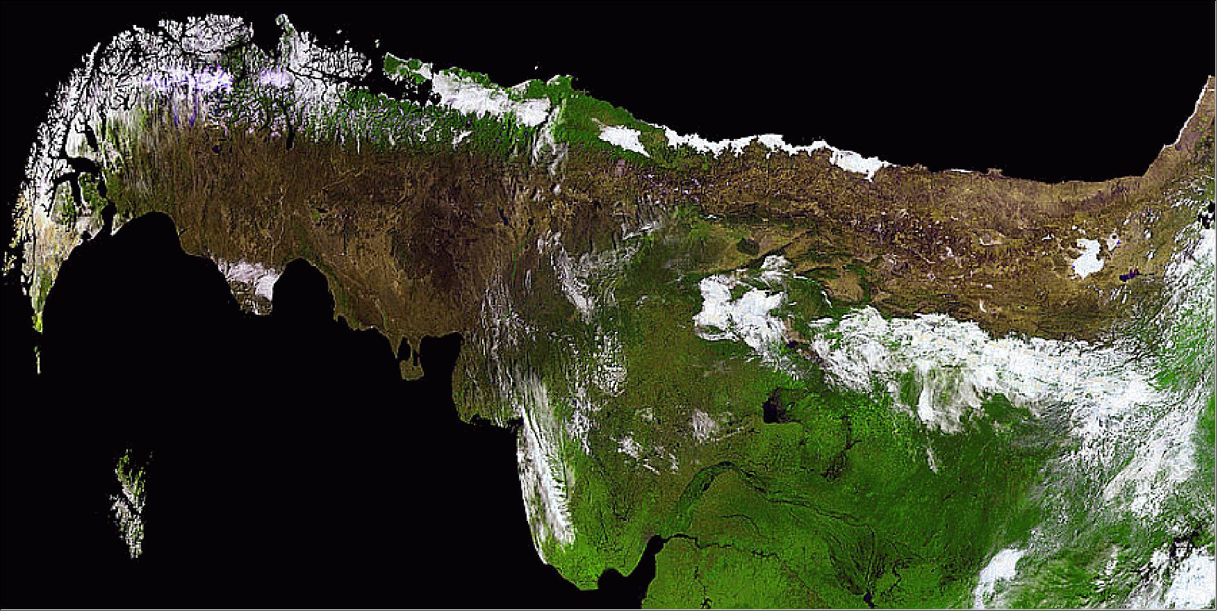
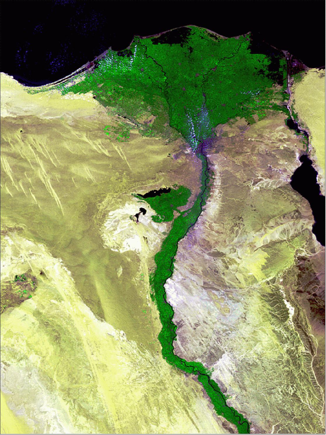

• February 2014: In its first two months of work, the vegetation-monitoring PROBA-V minisatellite has yielded a valuable harvest for around a hundred scientific teams around the globe: more than 5000 images, 65 daily global maps and six 10-day global syntheses, plus a quick peek at the Olympics. ESA released the PROBA-V image of Figure 61 (333 m resolution) on February 17, 2014. Cloud covers much of the Black Sea itself. The city of Sochi is a sea port on the coast of the Black Sea (right next to the border of Georgia), while the snow events are taking place in the resort settlement of Krasnaya Polyana in the Caucasus Mountains. 83)
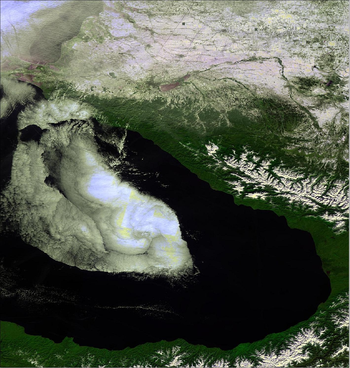
• January 2014: After the commissioning phase, the PROBA-V mission operations has been transferred within ESA to D/EOP (Directorate of Earth Observation Programs) as an ESA Earthwatch mission. The Vegetation images are online from the VITO/Copernicus user segment. 84)
• December 03, 2013: Less than seven months after launch, Earth-watcher PROBA-V is ready to provide global vegetation data for operational and scientific use. The crucial commissioning phase is now complete and the satellite has been declared ready for operations. 85)
It is anticipated, that with the data from PROBA-V, the user community, ranging from operational Copernicus services to scientific users, will be able to answer questions related to the state of global vegetation and its dynamic changes in a seasonal context. Furthermore, PROBA-V will extend the valuable time series that was started by the SPOT-4/5 Vegetation instruments 15 years ago.
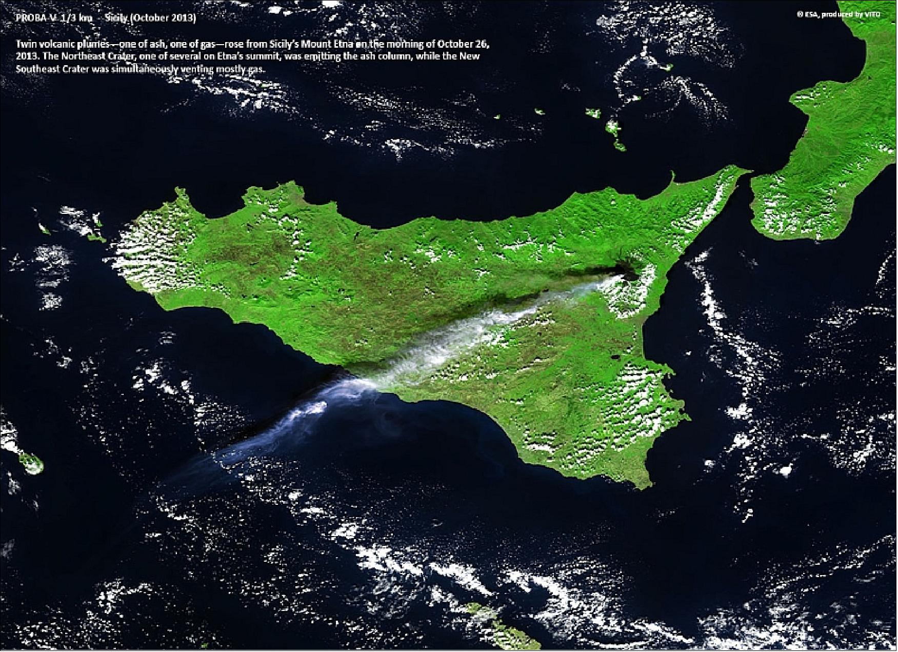
• On July 10, 2013, the first global VGT map of PROBA-V was provided, demonstrating that the minisatellite is on track to continue a 15-year legacy of global vegetation monitoring from space. 86)
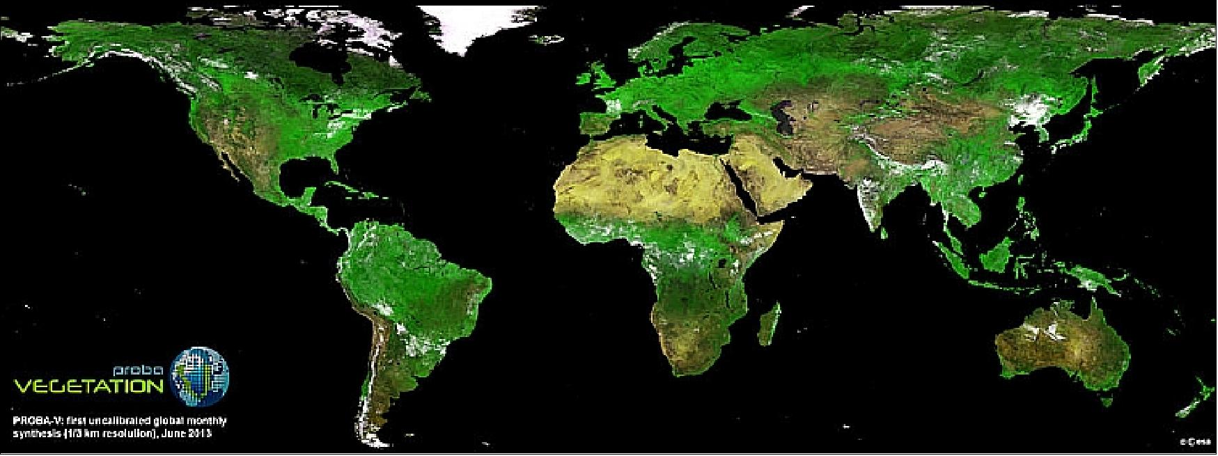
• July 02, 2013: The satellite is currently in its commissioning phase, which includes a careful cross-calibration of the Vegetation imager with its predecessor on France's Spot-5 satellite, to ensure data compatibility. 87)
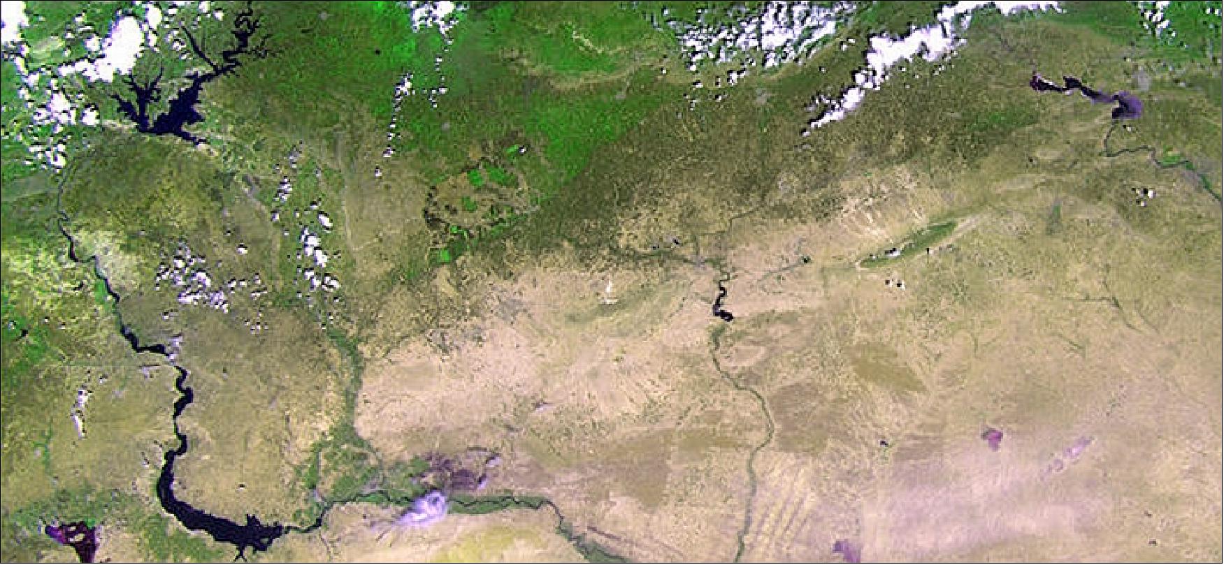
Legend to Figure 64: The area pictured is about 500 km across, with large reservoir lakes along the Euphrates River visible on the left, and another along the Tigris River on the right. Reservoirs and rivers secure water supply in the very dry region. They also form the basis for what is visible in different shades of green along the river water's edges and irrigated agricultural plots to provide food and income to the population.
In this image, the contrast between the green areas – some with agricultural plots – and the sparsely vegetated areas is evident. It demonstrates PROBA-V's ability to see slight differences in vegetation cover. Vegetation intensity and health can help in crop yield predictions and to map interannual changes in vegetation cover.
• June 13, 2013: An A320 Airbus overflying Scotland was the first aircraft 'seen' from space by a new receiver, the ADS-B (Automatic Dependant Surveillance-Broadcast) device of DLR. This verifies that tracking aircraft from space is possible. On May 23, 2013, the experiment was switched on for the first time, recording over 12,000 ADS-B messages within two hours, at an altitude of 820 km. The project team detected over 100 aircraft during the first pass over the British Isles, East Asia and Australia when the receiver was switched on. 88) 89)
ADS-B signals are broadcast by aircraft every second; they include aircraft position and velocity information. ADS-B equipment is being introduced on aircraft as a supplementary data source to the ground-based radar currently used to monitor air traffic. The problem with radar is that its coverage is restricted. Once out of the range of terrestrial radar stations, the continuous air traffic surveillance stops.
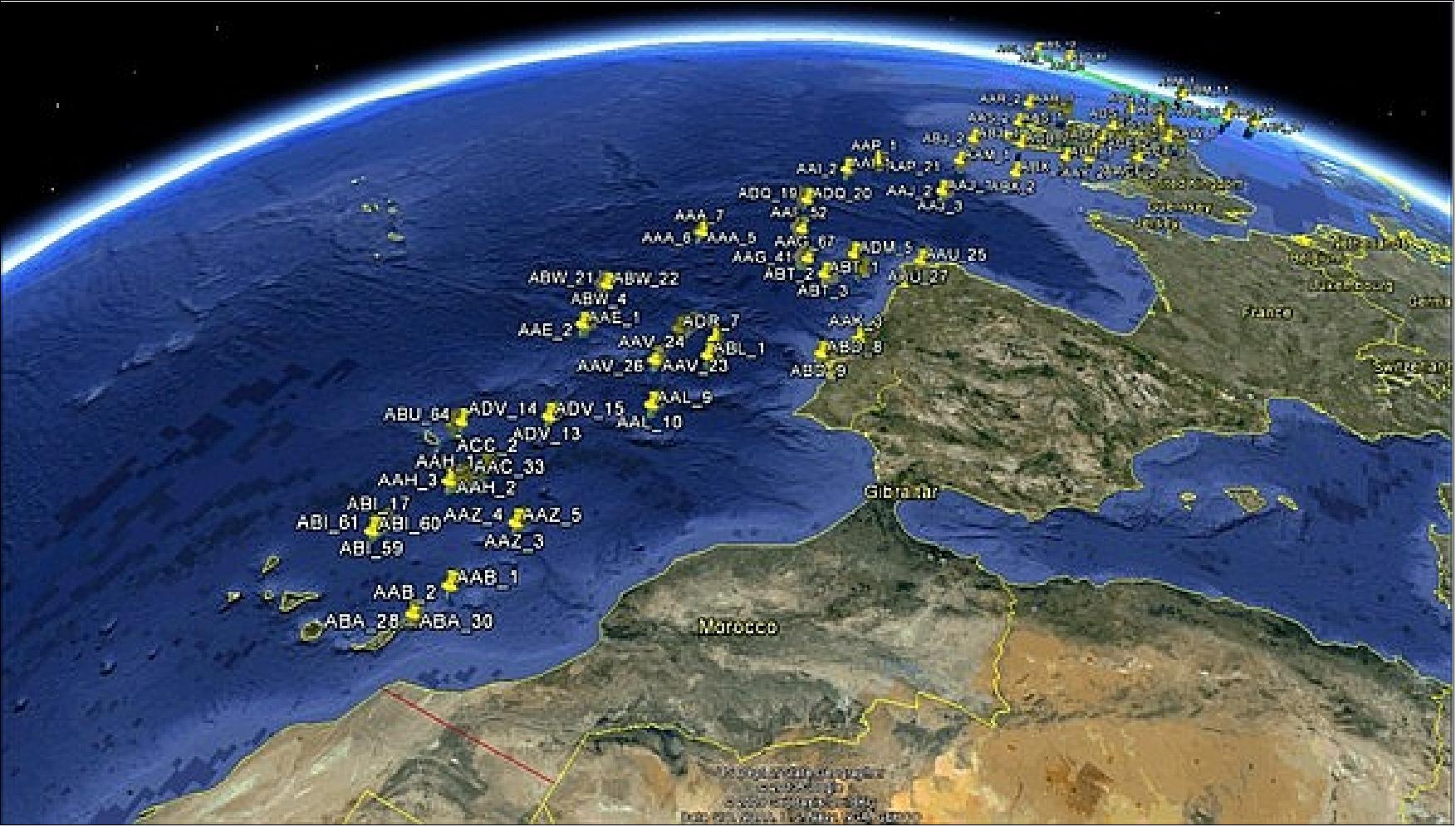
• May 17, 2013: The PROBA-V spacecraft is in good health following its launch on May 7, 2013. The Vegetation imager has been switched on and the first image has been captured over western France. 90)
- PROBA-V reached its orbit of 820 km altitude just 55 minutes after launch. The first LEOP (Launch and Early Operations Phase) milestone was to check the first signs of life from the satellite as it flew over the ESA ground station in Kourou 40 minutes after separation. Then a full telemetry session confirmed the stabilization of the satellite's attitude. The onboard computer used its magnetorquers to control the satellite's attitude and compensate for the spin imparted by the separation.
- Since then, the project has been checking the various subsystems one by one, confirming that they have made it through the stress of launch in working order. These initial checks are now being followed by a diligent commissioning of every single detail of the overall system platform, instrument and technology demonstration payloads, which will take the next few months.
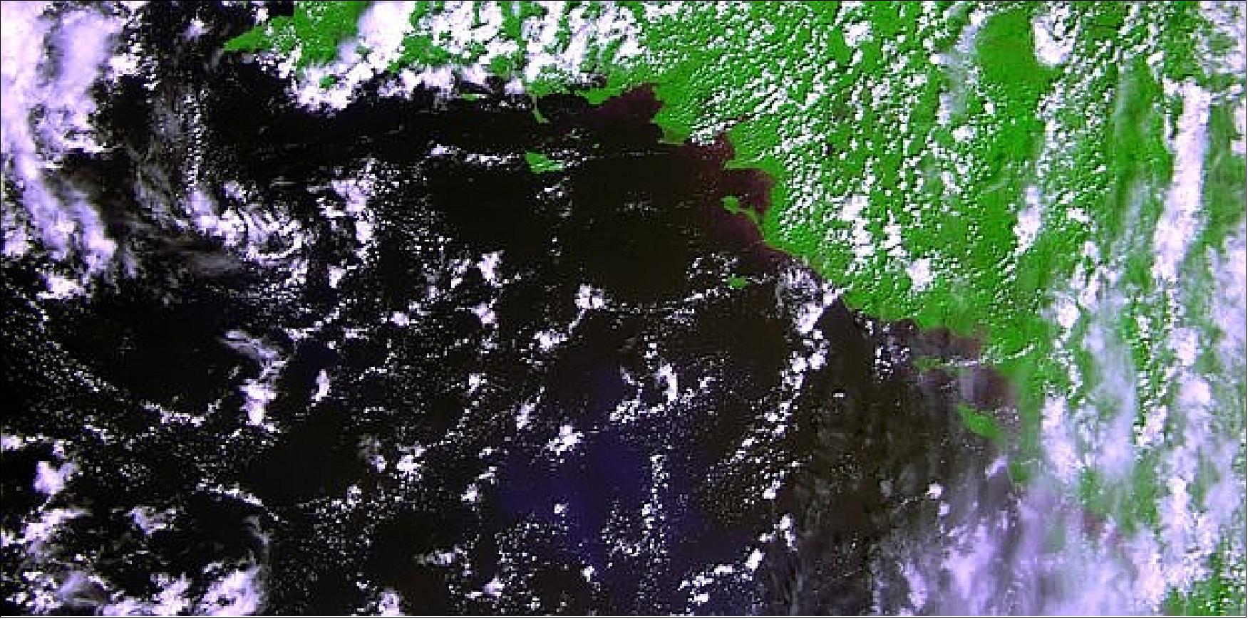
Legend to Figure 66: The image was generated using the three VNIR bands, blue, red and near-infrared (NIR) superposed, the green being replaced by the NIR. It has not yet been radiometrically or geometrically corrected. Less than a cubic meter in volume, the miniaturized ESA satellite is tasked to map land cover and vegetation growth across the entire planet every two days.
Sensor Complement
The major challenge in designing the payload is to make it compatible with the resources available on a small satellite like PROBA and at the same time accommodate the large swath. The selected solution is to divide the FOV (Field Of View) into three smaller parts and to use compact reflective optics elements using TMA ((Three Mirror Anastigmat) telescopes for each part. Each TMA is equipped with large VNIR and SWIR FPAs (Focal Plane Assemblies) to cover the large swath.
In addition to VGT-P, as a secondary mission objective, PROBA-V will fly four technology demonstration payloads.
VGT-P (Vegetation Instrument - PROBA)
The PROBA-Vegetation payload is a multispectral pushbroom spectrometer with 4 spectral bands and with a very large swath of 2285 km to guarantee daily coverage above 35 latitude. The payload consists of 3 identical SI (Spectral Imagers), each with a very compact TMA telescope. Each TMA, having a FOV of 34º, contains 4 spectral bands: 3 bands in the visible range and one band in the SWIR spectral range. The swath TFOV is 103º. 91) 92) 93) 94)
VGT-P is restricted to imaging land and dedicated calibration zones. On-board the spacecraft, there is for each spectral imager a land sea mask that is provided by the PI (Principal Investigator). The land sea mask removes the pixels that contain only sea and it dictates when each SI should be in imaging mode.
OIP (Optronic Instruments & Products, Belgium) is the industrial prime contractor for the payload and is responsible for the design and development of the PROBA-V instrument and AMOS (Belgium) is responsible for the manufacturing and alignment of the telescope. The major payload challenge lies in the fact that the wide-swath imaging instrument has to fit into a small satellite with limited resources. The TMAs and the SWIR FPA have to be developed for the VGT-P since no COTS products are available. 95) 96) 97)
Optical system | Type: Pushbroom instrument using a reflective optical design |
Spectral bands | VNIR B0: 0.415-0.500 µm (Blue) |
Optical parameters | Focal length: 109.6 mm |
Geometrical performance |
|
Spectral parameters | VNIR bands: 447-493 nm (blue); 610-690 nm (red); 777-893 nm (NIR) |
Mechanical concept | - 3 telescopes are mounted on highly rigid and light-weighted optical bench |
Electrical concept | - ROE (Read-out Electronics) of the FPAs partly on optical bench, partly on satellite panel |
Instrument mass, size | 35 kg, 200 mm x 812 mm xs 350 mm |
Instrument power consumption | 30 W (peak) |
Data compression | CCSDS 133.0 B-1 |
Data rate | 7.15 Mbit/s (after compression) |
DHU Interfaces with ADPMS | 2 Packetwire interfaces |
Each SI (Spectral Imager) contains one telescope, a beam splitter to separate the VNIR from the SWIR spectral bands, spectral bandpass filters to select the spectral bands, and the VNIR and SWIR focal plane arrays. The spectral bands will be realized by spectral bandpass filters centered on 460, 658, 834 and 1610 nm, with bandwidths of respectively 42, 82, 121 and 80 nm. The filters will be applied on the detector windows.
The optical axis of the central telescope will point to nadir and the two outer telescopes will point 34º from nadir. Together the three TMAs will cover a complete FOV of 102º. The optical system is telecentric, and the aperture is located at the position of the second (spherical) mirror.
The optical bench is passively cooled through a radiator and heaters compatible with the geo-location performances. The mass of the complete optical bench is about 20 kg, the total instrument mass is 35 kg.
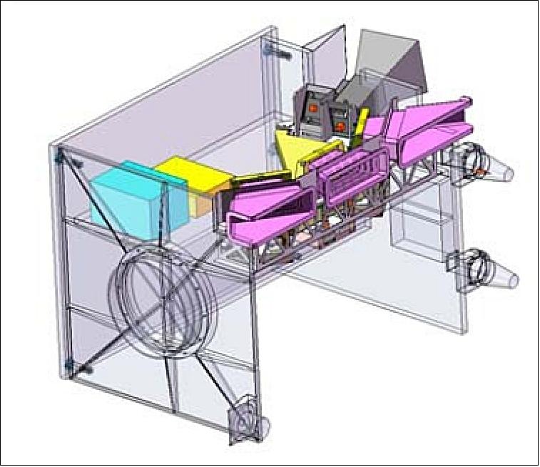
Figure 67 shows the payload mounted on the PROBA-V platform. Given the reduced size of the platform, a H-shape structure, the only practical location of the payload is on the anti-velocity panel. This accommodation, with respect to a solution with the payload in the middle of the structure, has the advantage of a very simple assembly and clean mechanical interface. The drawback is a larger temperature gradient due to the close vicinity of the payload to the solar panel.
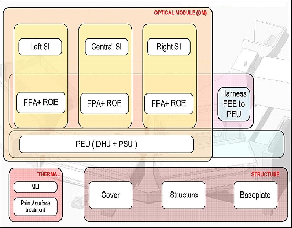
Legend to Figure 68:
- ROE (Read Out Electronics)
- PSU (Power Supply Unit)
- DHU (Data Handling Unit)
- PEU (Peripheral Electronics Unit)
- MLI (Multi-Layered Insulation)
TMA telescope development: VGT-P makes use of a set of three such telescopes, identical to each other. The purpose of the related ESA GSTP (General Support Technology Program) development is to demonstrate the feasibility of one item of the set with respect to its required optical quality, and to secure the instrument development. The entire telescope (structure and mirrors included) is an athermal design made of the same aluminum material. The mirrors quality is achieved by SPDT and the alignment rely on the very precise matching of the mirrors with the mounting structure.
Taking into account the mission constraints and objectives, including the innovative features of the instrument, a full-aluminum design was selected. This choice allows taking benefit from the recent developments in ultra-precision milling and turning techniques, as well as in optical aluminum production. Furthermore, this leads to a homothetic telescope behavior. The optical performance requirement of the telescope with regard to MTF (Modulation Transfer Function) is given in Table 13.
SPDT (Single Point Diamond Turning): Diamond turning is a process of mechanical machining of precision elements using Computer Numerical Control (CNC) lathes equipped with natural or synthetic diamond-tipped cutting elements. The SPDT process is widely used to manufacture high-quality aspheric optical elements from crystals, metals, acrylic, and other materials. Optical elements produced by the means of diamond turning are used in optical assemblies in telescopes, scientific research instruments and numerous other systems and devices. Diamond turning is specifically useful when cutting materials that feature aspheric shapes such as TMA surfaces.
Band | Nominal MTF (%) | 2σ MTF (%) | Max. frequency (lp/mm) |
Blue | 68.1 | 53 | 38.5 |
Red | 68.5 | 54 | 38.5 |
NIR | 68 | 53.7 | 38.5 |
SWIR | 71 | 62.4 | 20.0 |
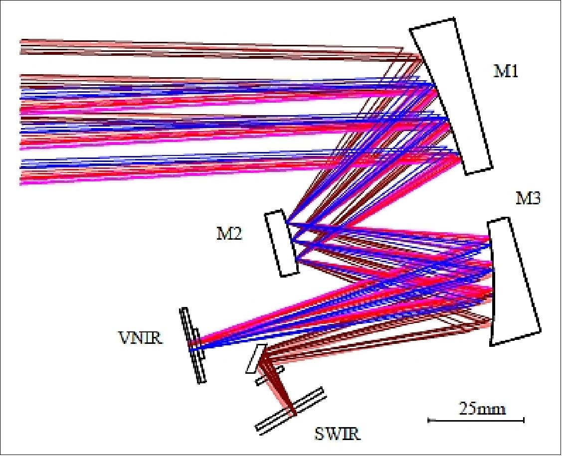
Baffle design (Ref. 93): The aim of the baffle design is to block the out-of-field light which could enter the instrument and reach the detector, directly or through one or several reflections on the mirrors. This 1st order analysis didn’t consider vanes on the baffles and diffusion on M1 of out-of-field light.
The preliminary baffle layout is presented in Figure 70. It comprises 7 baffles: 1 at the entrance aperture of the instrument and 6 placed inside the instrument. An aperture stop is also placed at the level of the secondary mirror.
The baffle #1 is placed at the entrance of the instrument. Its role is to limit the out-of-field light that could directly reach the mirrors. The combination of the baffles #1 and #2 stops the direct view of the M3 mirror through the instrument entrance. The length of the upper side of the entrance baffle is defined to stop the light which could directly reach the M3 mirror and that could not be stopped by the lower side of the entrance baffle and by baffle #2. Some out-of-field light can also reach the M2 and M3 mirrors after reflecting on M1. This cannot be totally avoided but the length of the lower side of baffle #1 has been chosen in such a way that this straylight is stopped by the baffle #3 after reflecting on M3. The baffle #3 is placed below the M2 mirror and stops the direct view of the M1 mirror by the VNIR detector. The baffle #4 is a critical location where reflection or diffusion on the M2 structure can occur and bring stray light to the VNIR detector which is very close. Vanes will be placed at this location. The baffles #5 and #6 are placed near the focal planes to isolate the detectors from each other. The baffle #7 avoids a direct view to the SWIR detector from the M1 or M3 mirrors.
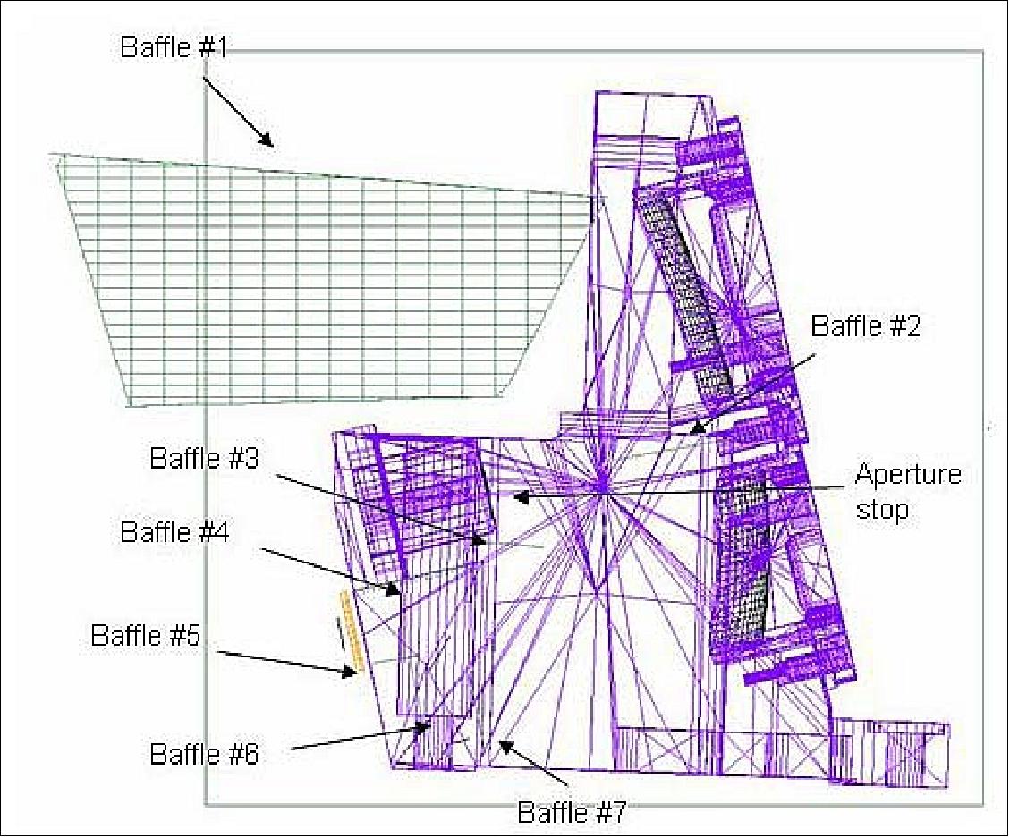
FPA (Focal Plane Assembly) design: The FPA is a very precise optical sub-module that comprises of a very accurately machined interconnecting structure in titanium, the VNIR and SWIR detectors, the detector windows, and a folding mirror used to optimize the packaging of the detectors, and thus minimizing the sub-module’s volume claim.
Within this assembly, the VNIR and SWIR detectors are precisely mounted relative to the FPA interconnecting structure. The FPA sub-module is mounted and aligned onto the TMA interconnecting structure and its position is justified via the VNIR detector - the SWIR detector inherits its position.
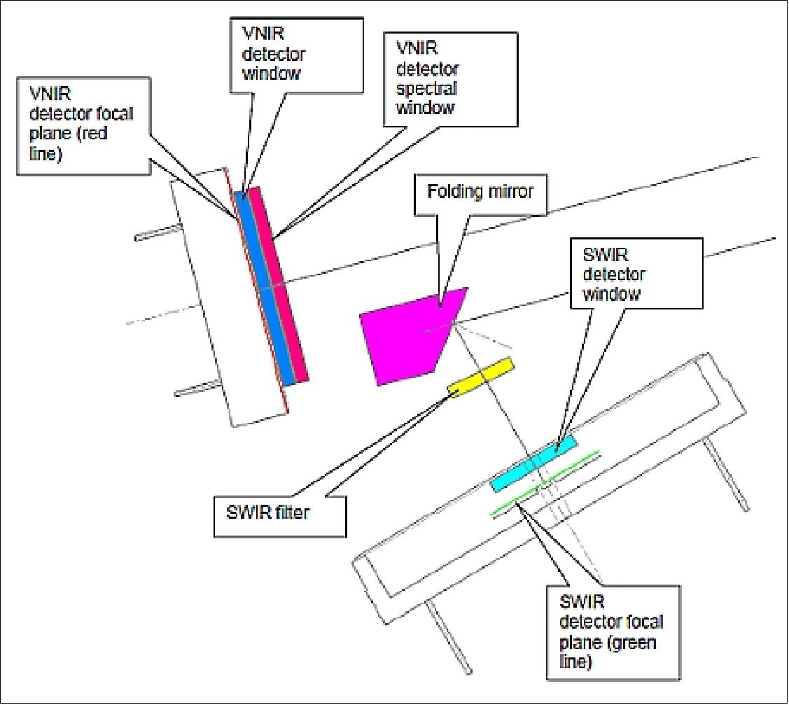
VNIR detector: The VNIR detector is a AT71547 (ex TH31547) quadrilinear detector from E2V. It consists of 4 photodetector lines, each line containing 6000 photodiodes HAD type (Hole Accumulation Diode) with 13 µm pitch. Each line includes its own anti-blooming system. Only 3 lines (blue, red and NIR) out of the four are used as separate array at a different wavelength. The spectral separation is done by the use of a spectral windows from Barr mounted on the detector transparent window (Figure 71). To reduce stray light falling on the arrays, the front and back surfaces of the detector window are coated with an anti-reflective coating, and the front surface also has a black mask applied.
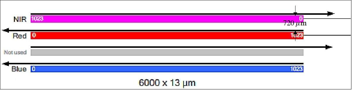
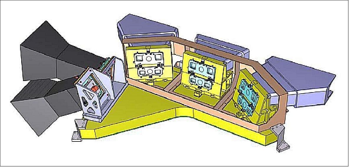
SWIR detector: The SWIR detector was specifically designed for PROBA-V by the company XenICs considering the large FOV. Due to the required imaging length of over 2700 pixels, sensor, it was decided to make the device in three sections, each consisting of a ROIC (Read-Out Integrated Circuit) chip and a PDA (Photodiode Array) chip with 1024 pixels on 25 µm pitch. The ROIC chip has been custom designed for the mission. The assembly is realized in a custom-designed kovar package of ~103 mm length with 72 pins shown in Figure 74. The large number of pins is required to operate and read-out the three ROICs independently for improved redundancy in case of failures during the mission. Due to the tight pitch, two rows of wire bonds on a 50 µm pitch are used to connect the ROIC chips to the PDA fan out (Ref. 91). 98)
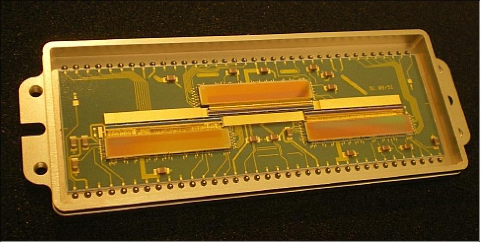
Parameter | Vegetation (SPOT series) | VGT-P (Vegetation on PROBA-V) |
Mass of instrument | 152 kg | 33 kg (with margin) |
Volume | 1.0 m x 1.0 m x 0.7 m | 0.81 m x 0.2 m x 0.35 m |
Swath | 2250 km | 2285 km |
GSD at nadir | 1165 m | 100 m (VNIR), 200 m (SWIR) |
GSD at edge of the swath | 1700 m | 360 (VNIR), 690 (SWIR) |
MTF at GSD | 0.3 | 0.3 |
Spectral bands |
|
|
SNR at L2 (W m-2 sr-1 µm-1) | 1 km product | 300 m product |
Geolocation accuracy |
|
|
Power | < 200 W | 43.2 W |
Thermal design of the VGT-P instrument: 99)
One of the major drawbacks of using multiple optical systems in parallel while imaging, is the effect of pointing inaccuracies due to thermo-elastic and mechanical deformations. It is obvious that such pointing errors can easily destroy the quality of the images. For the VGT-P, the stringent geo-location requirements demand the instrument to be thermally stabilized as much as possible to reduce any thermo-elastic disturbances.
Since the PROBA platform is fairly limited in the delivery of power, VGT-P needs to be very efficient in its power use. As a direct consequence, there is no possibility to have an active thermal control system to stabilize the instrument. The thermal design of the instrument must therefore be very carefully assessed and engineered.
• Thermal isolation: Firstly, as the surrounding satellite panels are heavily fluctuating in temperature during the orbit, it is of the utmost importance to shield the instrument thermally from these platform variations. To reduce the radiative heat loads from the environment, the instrument is completely wrapped in a 12 layer MLI. To reduce the conductive heat loads from the mounting plane, the instrument is mounted by means of titanium quasi isostatic mounting feet. These quasi isostatic mounting feet also play a major role in the transfer of the thermo-mechanical deformations from the underlying platform to the optical bench as they strongly reduce these deformations. Therefore, these titanium flexures as they are called not only serve as a thermal isolation, but also acts as a thermo-elastic isolator.
Power reduction: A natural step to reduce the thermo-elastic effects on the instrument is to reduce as much as possible the heat load on the optomechanics. Therefore, all non critical and heavy heat dissipating detector read-out electronics are separated from the optics. The FPAs of the telescope only contain the detector and electronic components which drive the radiometric performances of the instrument. These FPA electronics are connected through a flex rigid to the ROE (Read-Out Electronics) which is thermally and structurally disconnected from the optomechanics. All major heat dissipating components are located in there.
Obviously, also the central electronics (DHU and PSU) are separated from the optomechanical imaging system. By doing this, the total power dissipation on the optical bench is only 9W, which is less than ¼ of the total power dissipation of the complete VTG-P instrument.
• Heat dissipation: To dissipate this heat load, a radiator is needed. Several concepts were proposed and analyzed. The most efficient radiators point towards deep space which would enable us to cool down the complete instrument to very cold temperatures. This had a drawback that additional heaters would have been needed to stabilize the thermal regime of the instrument to normal working temperature. Moreover, as the instrument is always pointing downwards towards Earth, the radiator would have been located on the side of the instrument which naturally induces an asymmetry in the optomechanics. Such asymmetry is not desired in an imaging sensor with stringent pointing requirements. Moreover, heat pipes would have been mandatory to extract as efficient as possible all heat of the detectors towards the radiator which unnecessarily complicated the complete design.
From a thermo-elastic point of view, it was highly desirable to respect the symmetry of the instrument as much as possible and to symmetrically extract the heat from the FPA’s on the optical bench. Thus, it was chosen to locate the radiator in front of the instrument and point it towards the earth surface. As the earth is thermally quite stable at a fairly modest temperature and as the payload is always pointed nadir, this is the perfect heat drain for the instrument. The implementation of this concept reduces the complexity dramatically: the radiator, covered with aluminized Teflon, is connected through two thermal straps towards the front of the instrument without the need to install heat pipes.
• Stability: Stability is the key aspect of thermo-elastic performance. Of course, without the possibility of an active thermal control system, stability is quite difficult to achieve in a thermal environment which is constantly varying over the orbit.
To tackle this problem, the first stage was to avoid the randomness in the heat loads on the instrument and to have constant thermal regime along the orbit. As the payload is encircling the Earth with its radiator pointing at nadir, the heat load on the radiator is subjected to a varying regime from sunlit to eclipse and back. From the point of view of efficient power use, the imaging circuits on the instrument are switched off by the satellite if no imaging is needed (over the oceans, over the poles, during eclipse). This would induce different thermal regimes from one orbit to the other, which is not acceptable from pointing point of view. But leaving all electronics switched on during non operation is a no go considering the lack of power. As a compromise, during sunlit conditions and when the imaging electronics is powered off, a heater located on the detector with a heat load equal to the heat load of the detector and FPA is powered. In this way, the heat loads on the optical system remain constant during sunlit. During eclipse, all is switched off. - As a consequence, a constant thermal regime on the optics is established: during 1/3 of the orbit (eclipse) the radiator faces only IR and the instrument is switched off. During the 2/3 of the orbit, the radiator sees IR and albedo and the instrument is switched on.
• Gradients: The final challenge in the thermal design is to avoid thermal gradients in the instrument as gradients are hard to control and can severely affect the thermo-elastic performance. As already described, the heat extraction has respected the symmetry of the instrument. An unavoidable asymmetry is the location of the Star Trackers as they have their own limitations. The heat load from the FPA and the detectors on the telescopes is normally entering the instrument through the TMAs to the top skin of the optical bench. However, this would heavily distort and bend the optical bench as the top skin will expand more than the bottom. To reduce this effect, thermal straps are designed to extract most of the heat (4/5) from the detectors and the FPA towards the optical bench, the rest is still entering the TMA structure. To reduce the thermal bending, the heat straps are mounted on the side of the optical bench to avoid the bending of the bench.
Electronics design: The functional conceptual electronic design consists of three major building blocks:
4) The VNIR and SWIR ROE (Read-Out Electronics): The VNIR and SWIR ROE are the interface between the respective detector and the DHU (Data Handling Unit). The main functions of the ROE modules are to control the detectors, perform the A/D conversion, generate accurate bias to the detectors, and transmit the raw digital image data to the DHU. Additional functions are generating local biases and performing housekeeping measurements.
5) A centralized DHU (Data Handling Unit): The DHU is the central unit, acting as interface between the satellite and the VNIR and SWIR ROE. It is responsible for all the on-board data handling, image processing and temporal data storage, as well as for collecting the housekeeping data of the different sub-units. The main function are control and synchronization of the ORE, perform compression of the incoming image data as per CCSDS standard, packetizing of the image data before sending to the satellite OBC, collection and transmission of the available housekeeping data and processing of command data sent from the OBC over the serial communication link.
PROBA-V has three VNIR and three SWIR line sensors which compose three separated channels each. This leads to a total amount of 18 channels with 9 channels for VNIR each with a resolution of 5200 pixel and 9 SWIR channels each with a resolution of 1024 pixels. The 18 Channels have to be compressed independently with a variable compression ratio by the DHU. Furthermore, DHU supports bad pixel removal on basis of a bad pixel map which can be uploaded from. The compression is performed on an advanced overlapping tilling scheme. The DHU performs the following functionality: 100)
- Control & Monitoring of 3 VNIR and 3 SWIR
- Generation of camera syncs to the 3 VNIR and 3 SWIR with programmable time and delay
- Interface to VNIR/SWIR and separation of the incoming data streams into a total of 18 independent channel data streams
- Sorting of incoming data from a disordered arrangement to an adjacent pixel to pixel and adjacent line to line based arrangement supported
- Storage of data in SDRAM (required because of 2D wavelet based compression)
- Online lossless and lossy compression with selectable ratio and bypass capacity (independent selectable for each channel)
- Generation of source packets from the processed data with subsequent transmission via a PacketWire interface to S/C
- Interface for control & monitoring from S/C (TMTC Interface)
- RTC (Real Time Clock)
- Acquisition of HK data and provision of HK packet to the S/C.
The complete DHU functionality is implemented within two Microsemi RTAX 2000S FPGAs from ACTEL.
Image data handling approach: The advanced overlapping tiling scheme of the universal compression core is especially a challenge for DHU image data handling system. The number of lines according to the tile height (128) has to be collected prior to compression into a temporary SDRAM buffer to form one image. Since all spectral channels are read out simultaneously but have to be processed independently, the DHU has to format an overall of 162 (15 VNIR and 3 SWIR tiles per channel) overlapping tiles of the 18 channels and furthermore perform the bad pixel removal in real time. In parallel, due to the continuous data acquisition of the sensors, the subsequent received lines have to be stored in a different area of the temporary SDRAM buffer to provide a seamless data stream to the compression. With the constraints of spaceborne DHUs, a robust and deterministic architectural approach according to system constraints e.g. resource utilization, performance boundaries and requirements has to be provided.
The DHU has to perform the following processing steps on the acquired images:
- Storage of image line data from the instruments until a complete image is received
- Tile formatting and transfer to the compression core; in parallel bad pixel removal
- Storage of the compressed data from the compression core and additional packet formatting
- Transfer of compressed tiles over the PacketWire interface to the S/C.
All these processing steps have to be performed in parallel. The DHU comprises one centralized mass memory. To provide subchannel independent operations, the memory is sub-divided into VCs (Virtual Channels). Each VC is related to one of the SWIR and VNIR subchannel. Furthermore, to support the parallel processing of incoming data and image processing, a double buffer implementation is mandatory. Therefore, 18 x 2 VCs for image data exist in the architecture. Each VC allocates memory for 1 complete image (128 lines) in the mass memory and additional 18 VCs are provided for the bad pixel maps. On these VCs, constant data length transmissions are performed. Furthermore, the incoming compressed variable data length from the compression core is also stored in VC tile buffers. Two tile buffers are provided in the architecture in which data transmissions of variable length can be performed. Overall the DHU image data handling systems provides 56 VCs.
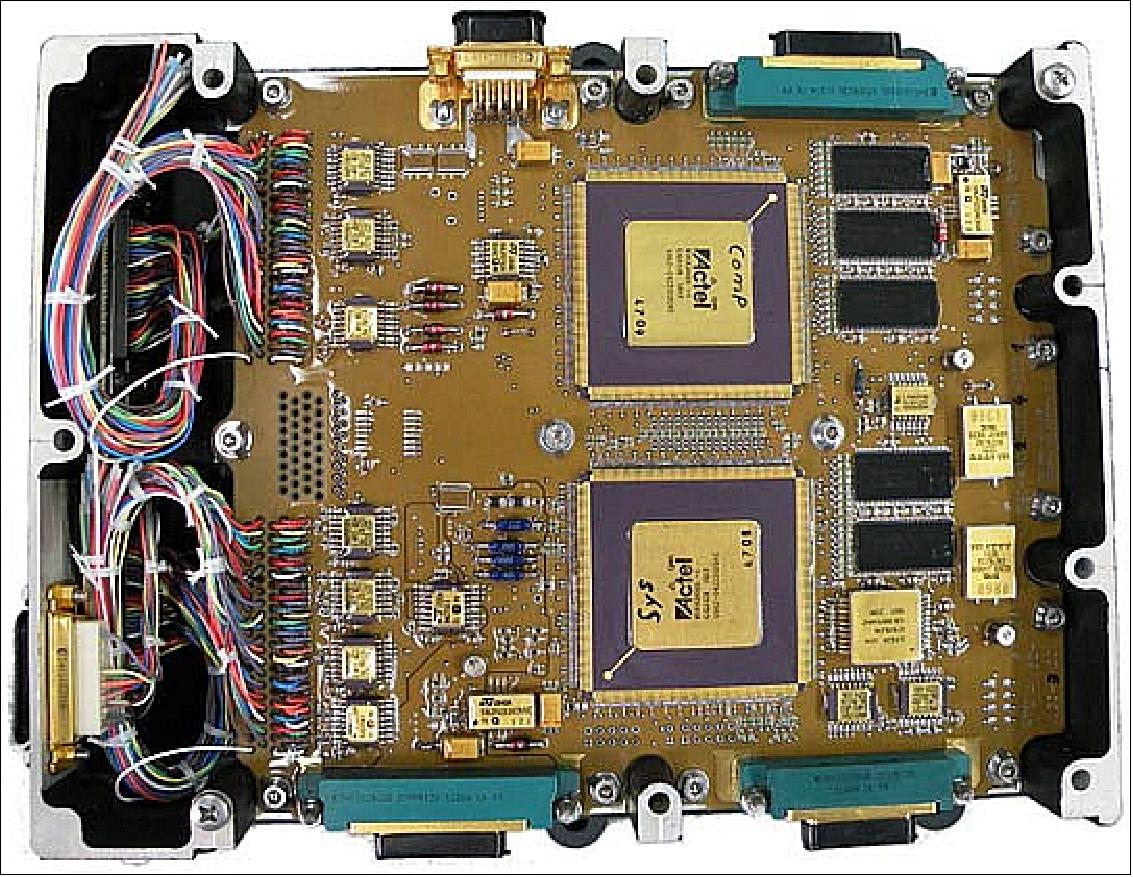
6) The PSU (Power Supply Unit): The PSU contains all the necessary DC/DC converters (i.e. LPLCs from TAS ETCA) to perform power conditioning to the different sub-units. It contains also the powering selection circuitry (by means of MOSFET) to individually switch on and off the different Spectral Imagers and heaters. The different power lines towards the spectral imager ROEs are also protected by current limiters within the PSU.
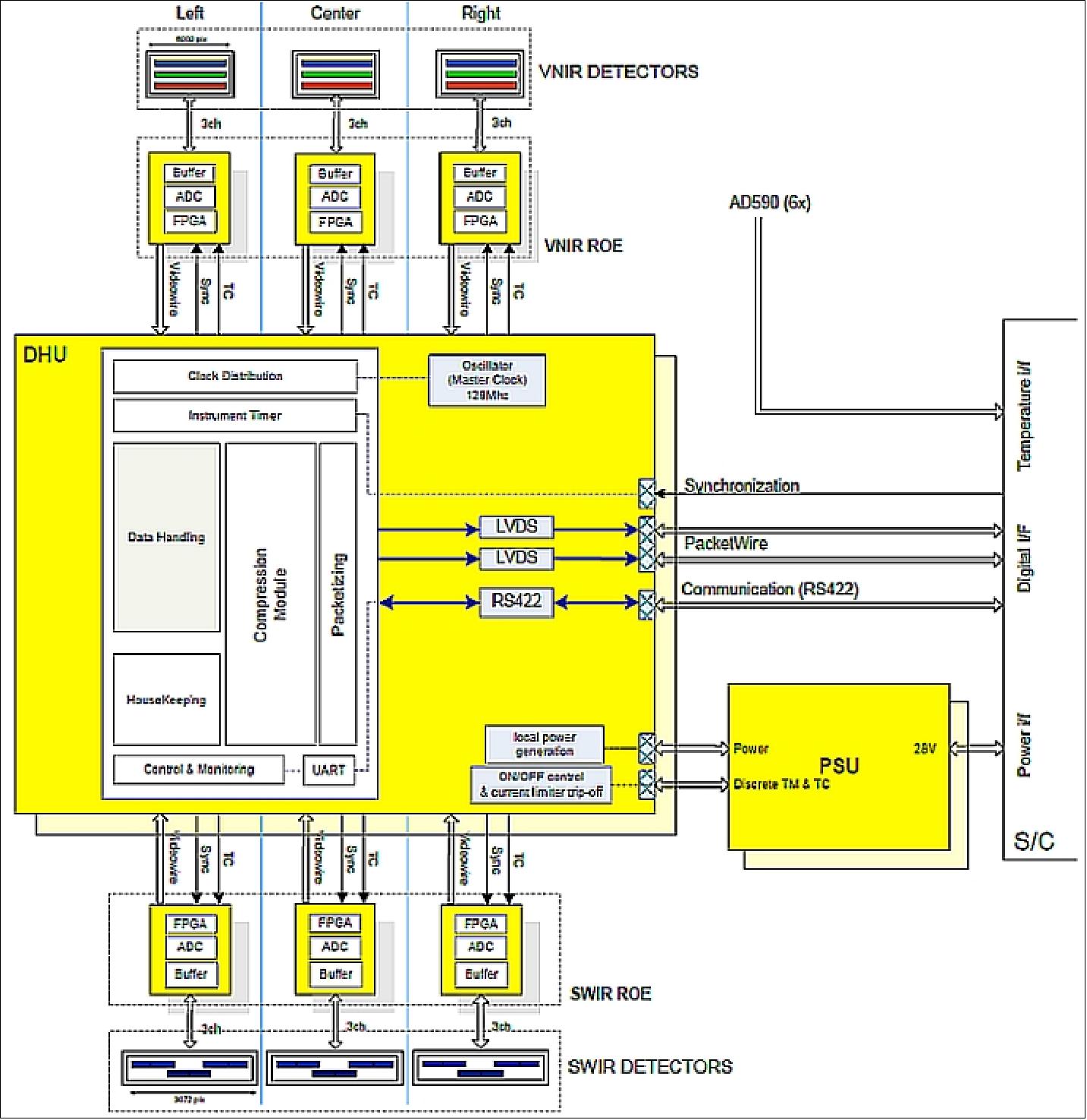
Since the electronics design is to be Single Point Failure Free, the above described concept is built in the following redundancy configuration:
• the DHU actually consists of 2 sub-units, one primary and one (cold) redundant
• the PSU has a more complex arrangement:
- fully redundant DC/DC converters with their associated TM/TCs
- fully redundant power distribution to DHU and survival heaters
- cross-strapped power distribution to ROEs, via a MOSFET diode –Oring (in line with the 3 ROEs partial redundancy principle).
• The VNIR and SWIR ROE cannot be built in redundant configuration as the detectors are directly mounted on these PCBs. However, if a failure should occur in one of the ROE units such that the instrument fails, the malfunctioning unit can be turned off and the instrument can continue functioning, but with reduced functionality.
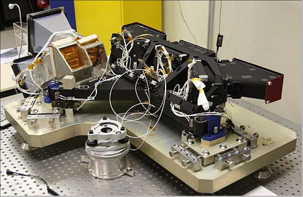
VGT-P Testing and Simulations
A test version of PROBA-V's wide-viewing multispectral imager, referred to as CHIB (Compact Hyperspectral Imager Breadboard), has been subjected to a combination of hard vacuum and temperature extremes in ESTEC’s Mechanical Systems Laboratory, simulating conditions it will face in space (Ref. 92). 101) 102)
CHIB consists of a wide (34º) FOV Three Mirror Anastigmat (TMA) telescope telecentric in the image space and equipped with a 2-dimensional focal plane array with a linear variable optical filter (LVF).
The CHIB optical design is shown in Figure 78. SPDT (Single Point Diamond Turning) enables the fabrication of complex aspheric shapes, which gives a freedom to design and manufacture a highly compact (90 mm x 110 mm x 140 mm) TMA.
A prototype TMA telescope was developed in 2009 through ESA's GSTP (General Support Technology Program).The idea was to combine the PROBA-V TMA with the wide 2-dimensional CMOS array (10000 x 1200), developed under the ESA-PRODEX program for the HALE UAV instrument MEDUSA, and a linear variable filter to create a compact wide swath hyperspectral imager. Based on a first analysis the following top level specifications have been derived for such type of instrument.
The mirrors and structure holding the mirrors are both manufactured in aluminum providing an athermal design. The telescope is telecentric: the variation of the angle of incidence of the chief rays on the focal plane is lower than 1º over the entire field of view, ensuring a negligible shift of the peak transmission over the interference filter. The LVF is positioned close to the focal plane, just in front of the detector.
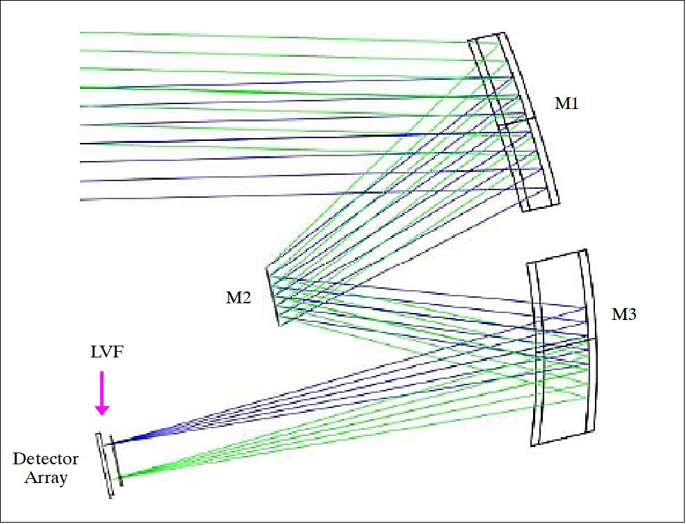
To fully exploit the very wide FOV of the telescope, the instrument is equipped with the large detectors developed by Cypress for Medusa. The detector is a 1200 x 10000 pixel CMOS image sensor with a pixel size of 5.5 µm x 5.5 µm. The main characteristics of the sensor are reported in Table 14.
Pixel architecture | 6 transistor pixel |
Pixel size | 5.5 µm x 5.5 µm |
Format | 10,000 x 1,200 (each detector) |
FCW | > 30000 e- |
Dark current | 600 e-/s @ 20ºC |
Operational temperature | ± 70ºC |
The LVF (Linear Variable Filter) is a fused silica plate coated plate with an interference filter with increasing thickness in along-track direction. The peak of the transmission curve varies with the thickness of the deposition. This implies that all detector pixels in a cross-track row receive information in the same spectral channel. The detector pixels in the along-track rows receive information in different spectral channels, and the closer pixels to each other, the less difference between the corresponding spectral channels. Thus, in principle, the total number of spectral channels is equal to the number of pixels in an along-track detector row covered by LVF. The filter used in the breadboard has operating spectral range 450 nm – 900 nm, FWHM spectral resolution of less than 15 nm and a gradient of the peak transmission wavelength of 60 nm/mm.
VGT-P calibration: Radiometric and geometric instrument performance measurements will be done both on ground and in-flight. The on-ground calibration of the PROBA-V instrument will be performed at CSL (Liège, Belgium) prior to integration on the platform at Verhaert Space. A complete calibration report describing the radiometric and geometric performance characteristics before launch will be compiled. Radiometric and spectral performance characteristics that will be verified on ground are: signal-to-noise, dark currents, linearity, stray light, pixel non-uniformity, polarization sensitivity, spectral response and spectral misregistration. Geometric performance characteristics include MTF, bore sight, spatial misregistration. 103)
The assessment of the PROBA-V performance, the analysis of the image quality and the calibration after launch will be performed by the PROBA-V IQC (Image Quality Center) located at VITO, Belgium. VITO is the processing center for the SPOT-4 and SPOT-5 Vegetation data and is operational since 1999. The Image Quality Center will ensure the highest possible image quality, both radiometrically and geometrically. Given the constraints on power consumption and the small size and weight of the platform, only vicarious calibration techniques will be used to monitor sensor performance over time; no on-board calibration facility is available.
Still, a complete calibration plan to assess the radiometric and geometric performances in-flight is being outlined. The objective of the calibration plan is to achieve a complete PROBA-V calibration at the end of the commissioning phase with :
• A full in-flight radiometric characterization and calibration including :
- Dark current determination
- Calibration of the absolute calibration coefficients of the three cameras
- Equalization among detectors or multi-angular calibration: to correct for sensitivity variation over the PROBA-V wide field-of-view
- Characterization of response non-linearity
- Radiometric image quality performance analysis: Noise, MTF, SNR
• A full in-flight geometric characterization and calibration including :
- Geometric sensor model calibration: Post-launch check and calibration of all parameters of the geometric sensor model for each sensor including 104)
- Continuous absolute geometric accuracy check
- Image geometric quality performance indicators such as absolute location accuracy, multi-temporal coregistration accuracy, multi-spectral co-registration accuracy.
Vicarious radiometric calibration: 105)
• Calibration over Rayleigh scattering (oceans)
• Calibration over deep convective clouds (oceans)
• Calibration over sun glint (oceans)
• Calibration over stable deserts
• Calibration over Antarctica (equalization)
• Calibration over oceans during night (dark signal)
• Stability check using the moon
• Calibration validation over Tüz Gölu (meaning slat lake). Tüz Golü is the second biggest lake in Turkey, located in the Central Anatolia Region.
• Calibration validation under flights with the APEX airborne sensor at high altitude.
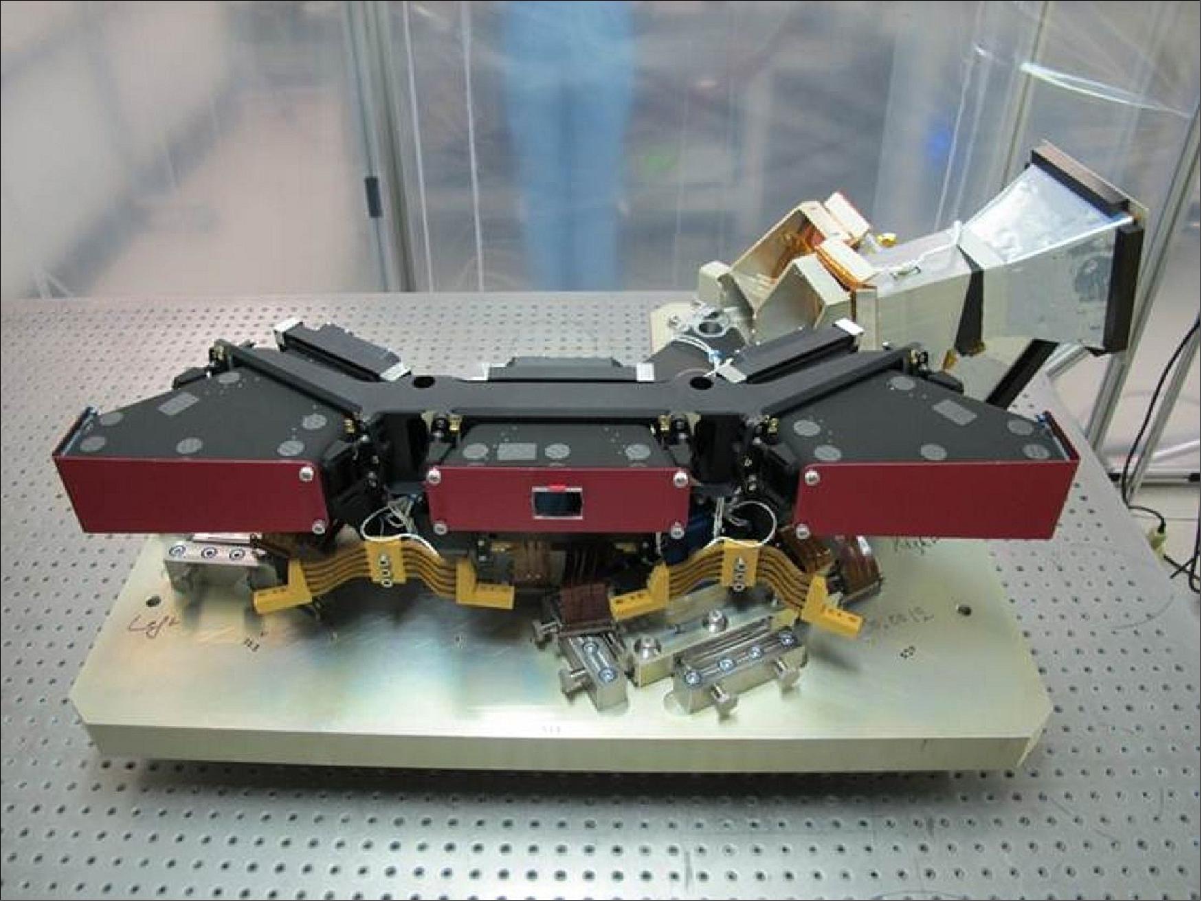
Technology Payloads
Next to the VGT-P (Vegetation Instrument-PROBA) sensor complement, the spacecraft is offering slots for technology demonstration payloads.
EPT (Energetic Particle Telescope)
The EPT instrument is developed by QinetiQ Space and the Centre of Space Radiation in Belgium. The objective of EPT is to collect more information on radiation conditions prevailing in Earth orbit. EPT will measure the high-energy particle fluxes with very good energy, angular and mass resolutions. It measures the energy deposited by charged particles into twelve sensitive elements and processes the information to identify the particles (0.2-10 MeV electrons, 4-300 MeV H and 16-1000 MeV He ions) and to determine their energy spectra and angular distribution. 106)
The instrument consists of two "particle telescopes" placed in series separately adapted to low and high-energy ranges. The low-energy section consists of two silicon detectors. The high-energy section is a so-called "range telescope" in which the thicker silicon detector is used as a (DE) sensor and a stack of absorbers and scintillator-based detectors produces a digital measurement of the total energy (E).
The EPT overall dimensions are 205 mm x 205 mm x 190 mm. It has a mass of ~ 6 kg, with the electronic readout included. The power consumption is < 6 W. The maximum energy-dependent geometrical factor of the detector is ~1.5 cm2 sr. The radius of the EPT circular aperture was set to a diameter of 35 mm. The resulting maximum field of view angle is 50º.
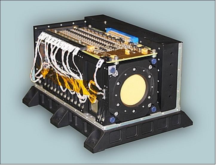
Due to the widely varying fluences of electrons, protons and heavy ions within the radiation belts, it was found necessary to provide this instrument with a stunning in-flight particle discrimination capability. This was achieved by performing a thorough characterization of the EPT by an intensive Monte-Carlo simulation using GEANT4 software. With this optimized design procedure a background-free counting is obtained, even in the channels devoted to particles of very low abundance in space.
Note: The EPT commissioning has been fully successful, with positive verification of all its functionalities (Ref. 25). Moreover a campaign has been performed over the SAA ( South Atlantic Anomaly), where the satellite was commanded in different attitudes to measure the so-called PAD (Pitch Angle Distribution) of proton particles in this region of the Earth (Figures 81 and 82).
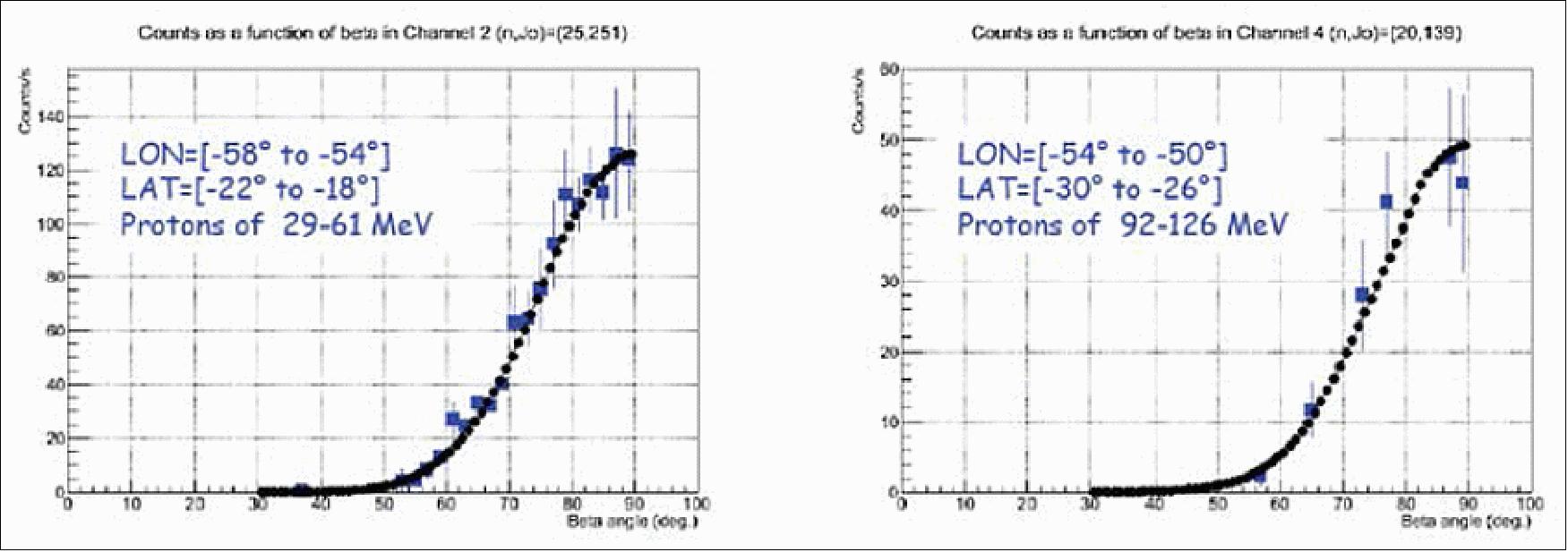
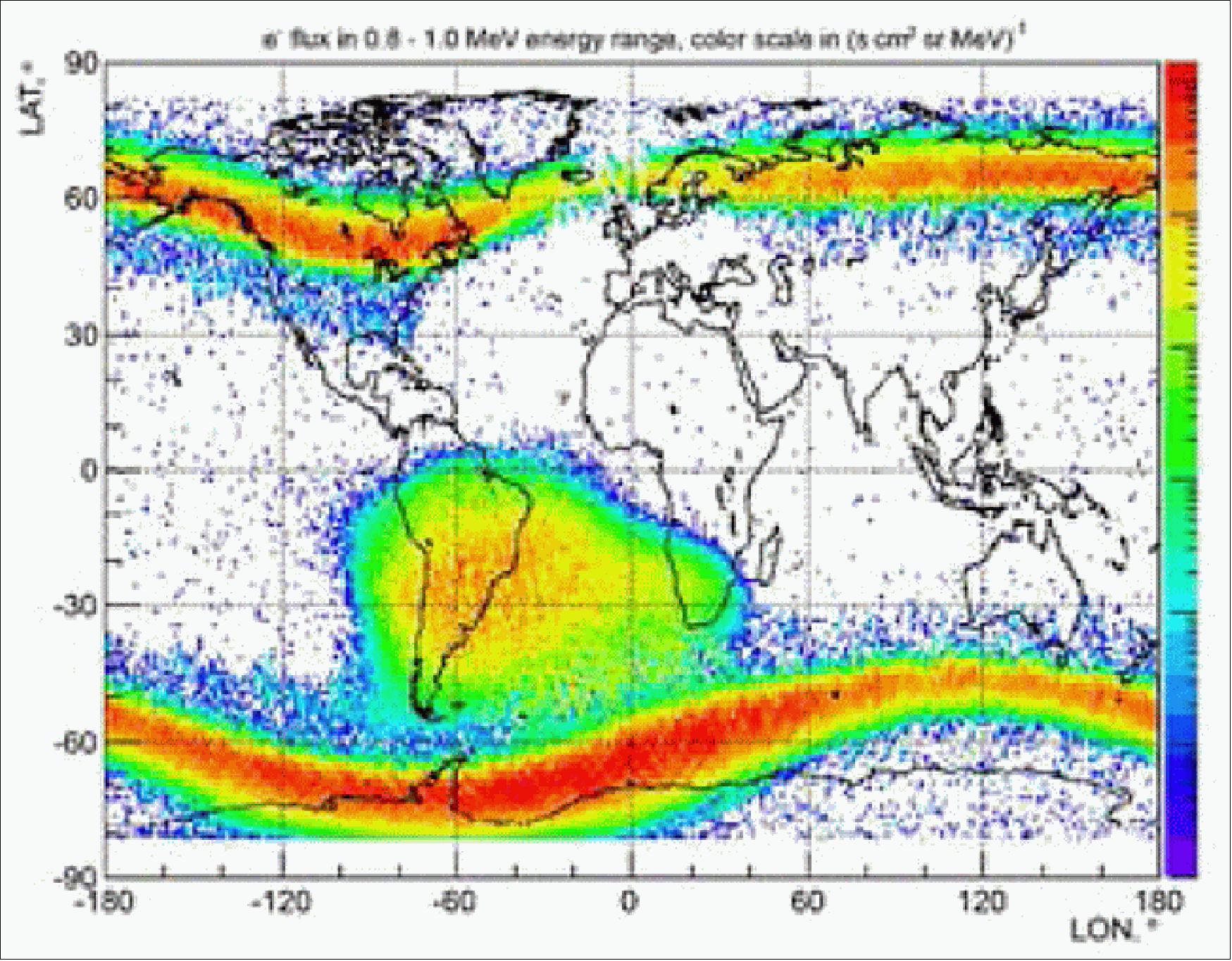
GREAT2 (GaN Reliability Enhancement and Technology Transfer Initiative)
ESA has identified GaN (Gallium Nitride) as a key ‘enabling technology’ for space, establishing a European consortium to manufacture high-quality GaN devices for space uses, referred to as GREAT2. Among the GREAT2 prototype designs is an X-band integrated circuit design. An extra X-band transmitter incorporating a GaN amplifier will be flown in parallel to PROBA-V’s initial pair of standard GaAs transmitters. The GaN amplifier has been developed at Syrlinks, former TES (Thales Electronic Solutions).107) 108)
The main objective of GREAT2 is to measure key parameters of the GaN RF power amplifier in orbit, validating the technology. Moreover, the demonstrator will provide additional redundancy to the main X-band transmitters of the platform.
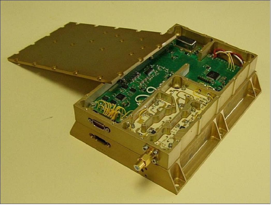
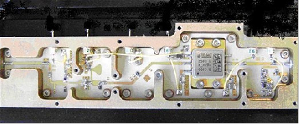
The X-band transmitter on PROBA-V is produced by Syrlinks in Germany, with the GaN amplifier coming from TESAT in Germany. This amplifier is among the earliest outputs of an ESA-led European consortium to manufacture high-quality GaN devices for space uses: the ‘GaN Reliability Enhancement and Technology Transfer Initiative’ (GREAT2). This innovative amplifier also has an adjustable power output, so its use should help to conserve the small satellite’s power consumption while also providing extra redundancy.
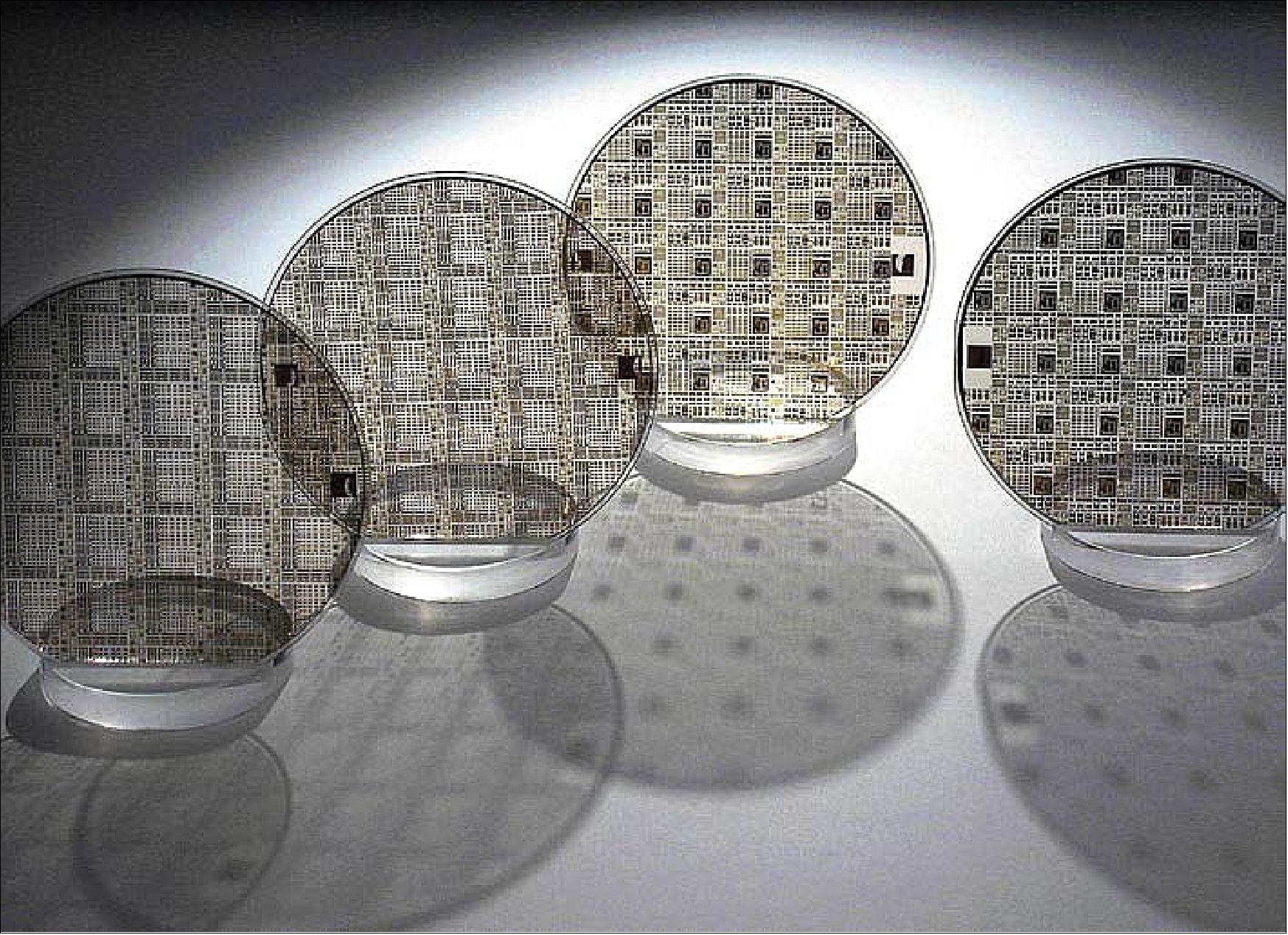
ADS-B (Automatic Dependent Surveillance-Broadcast)
ADS-B is an air traffic surveillance technology to provide specialized air traffic management and air traffic control services as part of the Next Generation Air Transportation System. The objective is to demonstrate space based reception of ADSB signals transmitted by aircraft (1090 MHz). The system involves aircraft broadcasting their position, altitude, velocity and other measurements on an automatic basis every second or so. Currently air traffic controllers on the ground rely on radar contacts to gain an overview of air traffic. But with ADS-B transmissions, aircraft remain continuously visible, not only to controllers, but also to other suitably equipped aircraft. ADS-B requires no costly ground infrastructure to implement – so sparsely-populated countries such as Australia have been enthusiastic early adopters (Ref. 14).
The idea with this payload is to take up an ADS-B system as is, foregoing any costly equipment upgrades, and investigate if it is technically feasible to receive ADS-B signals in orbit. PROBA-V will demonstrate how many aircraft can be observed worldwide and which types – different-sized aircraft are assigned ADS-B systems with differing signal strengths. Over the next two years, researchers intend to test, for the first time, whether continuous monitoring of aviation routes is possible. At present, this cannot be achieved in non-radar airspace; location monitoring from space could close this gap.
When an aircraft flies over the major oceans, large areas without infrastructure or the Polar Regions, it is no longer trackable by ground radar stations – the range of the stations is insufficient. But the aircraft continuously transmit ADS-B signals, with information such as altitude and speed — the DLR project team wants to make use of this. In initial experiments, the project has already proved to be successful. In 2009, during a series of high-altitude balloon flights in northern Sweden, the receiver was able to pinpoint an aircraft flying 1100 km away, from a height of about 30 km. For example, the project could 'see' a flight from Beijing to Amsterdam over the North Sea. In a further experiment in 2012, the researchers flew their receiver on a balloon at an altitude of 40 km and examined the interfering signals that it must cope with in a heavily flown and radar-monitored area. 109)
Instrument: The ADS-B device is provided by DLR and SES Techcom of Luxembourg, the main objective is to test (space qualify) the ADS-B electronic boards in flight-representative configuration to evaluate TID (Total Ionizing Dose). The basic design concept of the ADS-B receiver (1090ES RX) is a single conversion superheterodyne receiver with a down conversion of 1090 MHz to an intermediate frequency of 70 MHz. The IF sampling at 70 MHz is done by a 16 bit ADC at 105 Msps (Mega samples per second).
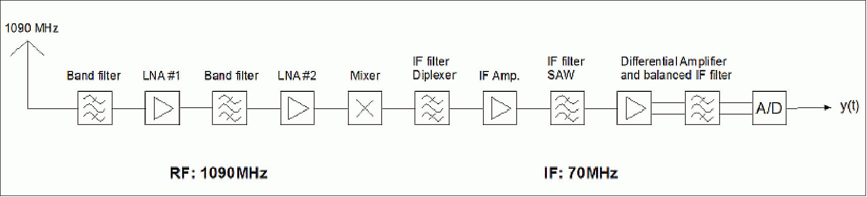
The digital part of the receiver is built around a Cyclone IV FPGA from Altera which combines the complete data processing as well as the communication with the onboard computer of the PROBA-V spacecraft. The digital and the RF section of the receiver are built on an individual PCB each, connected with a 37 pin MDM PCB connector. 110)
The FPGA comes with a 32 bit embedded processor to handle the satellite-borne interface. The communication to the spacecraft and commanding of the receiver is done through RS-422 UARTs (Universal Asynchronous Receiver/Transmitters) at a baud rate of 115 kbit/s. The input sensitivity of the receiver depends on the frequency condition of the incoming message and has a minimum trigger level of about -96 dBm.
Spaceborne ADS-B antenna: The antenna used for ADS-B over Satellite is an antenna array of two elements. Each element is a capacitive fed, shorted patch antenna. There is no direct mechanical bonding between the feeding structure and the patch. This makes the patch assembly very easy. Except for the feeder no dielectric material is used. It has been found that this gives an extra 12% gain increase. The patch antenna is shorted in the center of the patch to the ground plane of the spacecraft structure. This avoids potential charging.
Antenna type | Planar with two elements |
Frequency | 1090 MHz |
Gain | 11.2 dBi |
HPBWAZ (Half Power Beam Width) in azimuth | 33º |
HPBWEL | 73º |
Polarization | Right Hand Circular |
For the project team, tracking flights from a satellite is new territory. So far, no satellite has been used to receive ADS–B signals. In this first test, the characteristics of how aircraft radiate the ADS–B signal will be recorded. In the frame of the project, SES Techcom developed and implemented the ground data processing center, which retrieves, processes, analyses and stores all ADS-B data received from the PROBA-V satellite. 111)
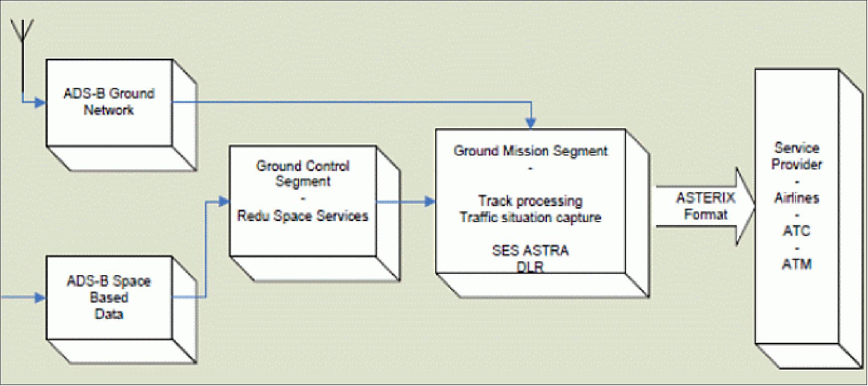
The pioneering ADS-B payload will be followed by the in orbit validation mission, which will demonstrate the full technical scope of spaceborne ADS-B. ESA (European Space Agency) has contracted Thales Germany for the development of this next generation ADS-B system, which is progressing on schedule with strong participation of the Luxembourg space industry, such as LuxSpace, with the TRITON microsatellite platform to support the future demonstration mission.
SATRAM (Space Application of Timepix-based Radiation Monitor)
The SATRAM instrument is contributed by CSRC (Czech Space Research Center) and the Czech Technical University. SATRAM is a radiation monitoring system based on the Timepix detector family which was developed by CERN for terrestrial applications. The Timepix detector is capable to detect all charged particles, including MIPs (Minimum Ionizing Particles) and heavy ions, depositing more than ~5 keV in the pixel sensitive volume with an efficiency of 100%. Based on the PROBA-V results, a full operational radiation monitoring will be developed for future missions (Ref. 12).
With the SATRAM payload mounted on the external side of the PROBA-V satellite’s bottom board, the Timepix detector determines, over a wide range of particle fluxes, energies, and for a broad field of view, the composition and spectral characterization of the mixed field radiation environment. The per-pixel energy sensitivity provides LET (Linear Energy Transfer) spectra and enhanced particle-type resolving power and directional sensitivity for energetic charged particles. Results can include spatial- and time-dependent distributions of the radiation environment along the satellite orbit.
The SATRAM payload contains an FPGA controlling the Timepix detector and providing communication with the spacecraft, along with housekeeping, data compression and configuration.
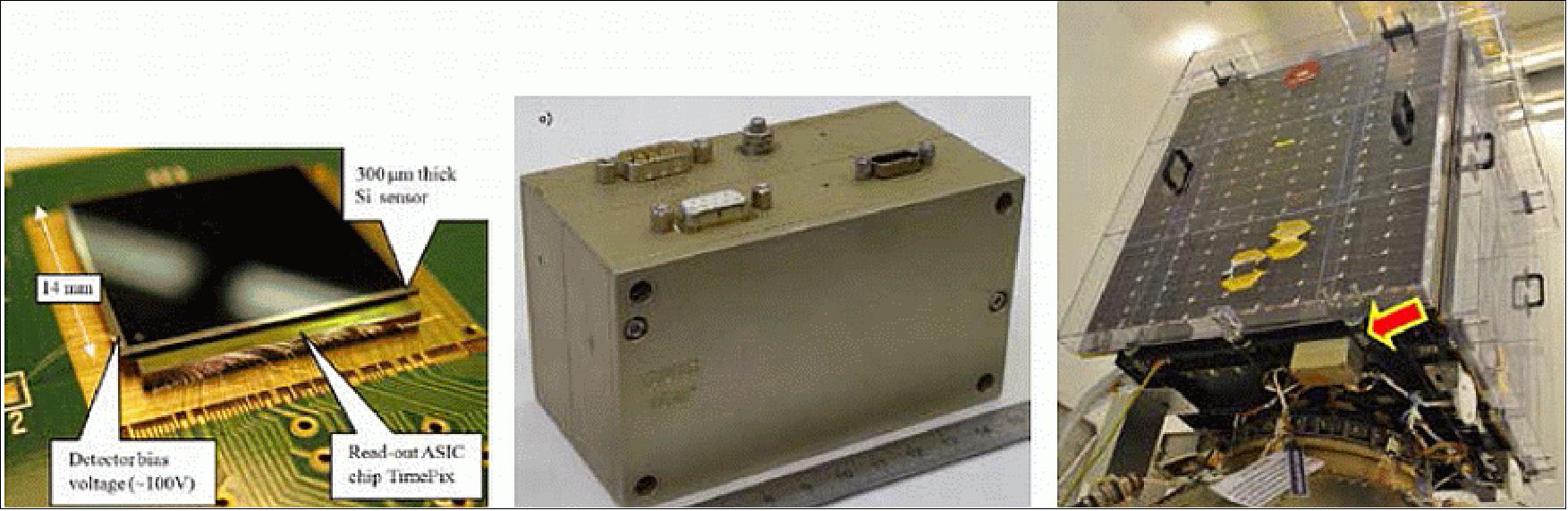
SATRAM has been active on a permanent basis since June 2013, collecting data analyzed by the IEAP (Institute of Experimental and Applied Physics) at the Czech Technical University in Prague.
The SATRAM unit flying on PROBA-V is the first deployment of the Timepix detector in outer space. Based on its successful commissioning and the optimization of its detector configuration and settings on PROBA-V, a second version of the SATRAM detector is under development, to be possibly flown on the future ESA missions.
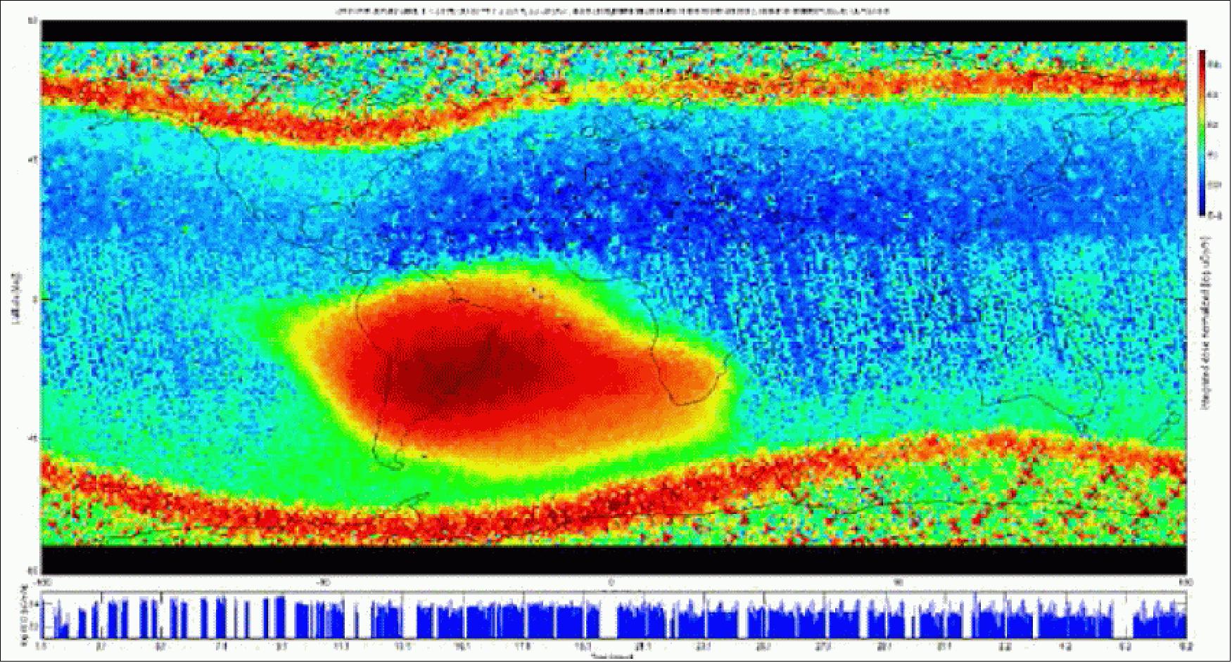
HERMOD (High Density Space Form Connector Demonstration)
The HERMOD device is a collaboration developed by the Norwegian T&G Elektro and the Spanish DAS Photonics companies. The objective is to test and validate the capacity of a novel multi-line optical fiber and connector design to operate reliably in the space environment. Light-based fiber optics offer numerous improvements on metal wiring for future space missions, including increased bandwidth, reduced mass and decreased sensitivity to temperature, radiation and electromagnetic interference.
The payload electrooptics generate different digital signals to pass through four different optical cables made of 12 fibers and then compare the returned message to the initial one, counting up the number of errors over time. Already employed in terrestrial sectors including the oil industry, these multi-line optical fibers were already being ground-tested for space as part of ESA’s General Support Technology Program when the opportunity arose to fly on PROBA-V. A crash effort brought the payload to flight readiness within six months (Ref. 14).
Figure 90 provides a simplified view of one experiment’s channel. In total, four identical channels are under test, each one with different optical harness configuration. A continuous data stream is injected into the optical cable and a BER (Bit Error Rate) is computed at the other extremity. Each channel has been differently biased to evaluate in-orbit degradation.
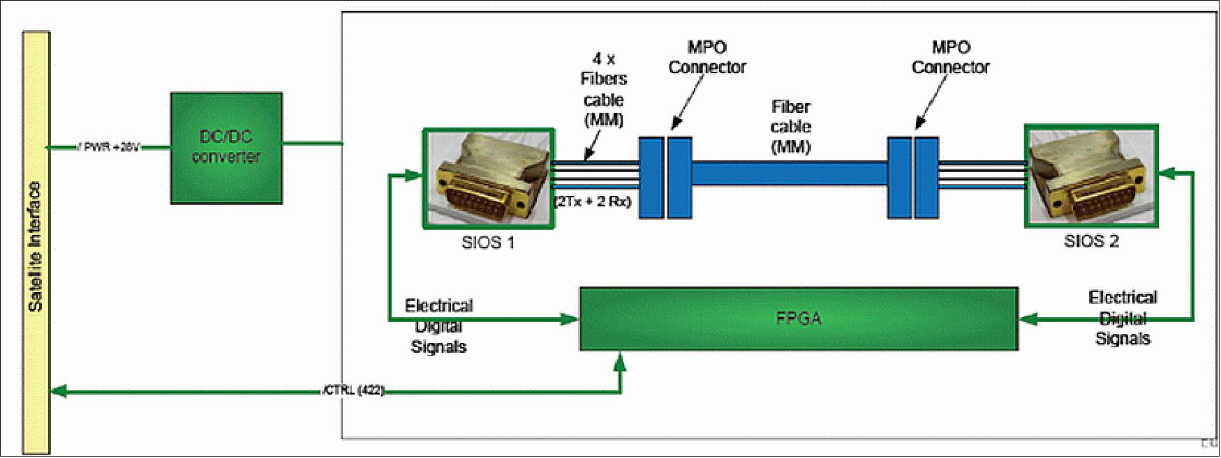
All the channels have survived the launch and no BER has been measured with the exception of the 3rd channel, currently recording a BER of 5.7 x 10⁻¹⁶, that exhibits from time to time a burst of errors due to synchronizing issues of the initial data frame. It is expected to observe during the operating life of the payload the first errors within the channel 2, that was designed on purpose with reduced power margin.
Originally planned to be activated in the frame of the PROBA-V mission for couple of days per month; the HERMOD payload has been continuously powered on-board since its initial activation.
HERMOD was selected for flight on PROBA-V less than year before flight, and the equipment has been developed in less than six months from kick-off to integration on the satellite.
Ground Segment
The PROBA-V Mission Control Center (MCC), located at the ESA Redu ground station, is controlling and monitoring the satellite. The PROBA-V MCC hardware and software infrastructure benefits from the generic components already developed for the previous PROBA missions (Ref. 7).

The MCC will be used for instrument monitoring and for issuing instrument calibration requests. During nominal operations, the use of a single TT&C ground station in Redu is foreseen for telecommanding and housekeeping telemetry reception in S-band. The utilization of an additional ground station is foreseen during LEOP and commissioning, to provide additional access to the satellite in the same band. The instrument data and the associated ancillary data are retrieved in X-band via additional Data Reception Stations on the Northern Hemisphere (Kiruna, Fairbanks, Alaska).
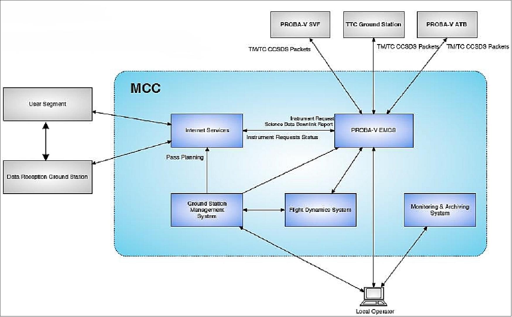
User Segment
The User segment, developed by VITO (Flemish Institute for Technological Research), Mol, Belgium, has the task of processing the raw data delivered by the Flight and the Ground segments and to distribute the mission products to the User Community of VGT-P. The User segment consists of the following elements:
- DIF (Data Ingestion Facility) which receives the communication raw data from the Data Reception Station and processes these into instrument, housekeeping and ancillary (orbit, attitude, time correlation data. The PF (Processing Facility) is responsible for all image processing tasks. Triggering of the individual data processing tasks within the PF is controlled by the PQC (Product Quality Center) that is responsible for the quality of the intermediate and final data products used within the PF.
- IQC (Image Quality Center) which encapsulates the calibration workflow of the instrument detectors and is as such responsible for the availability, the correctness and high-level quality of all calibration files used within the PF. The IQC is supported by an Image Quality Team continuously monitoring the quality of all calibration files.
- PDF (Product Distribution Facility) which is responsible for the distribution of all data products through a dedicated WWW interface. Whenever available calibration files need correction or improvement, the IPC (Instrument Programming Center) will request corresponding observations via the MCC in Redu. All data products to be delivered to the external users as well as all critical mission data will be archived within the LTDA (Long-term Data Archive). 112) 113)
The PROBA-V User segment will have a GSCDA (GMES Space Component Data Access) compatible interface to allow data services towards ESA Users.
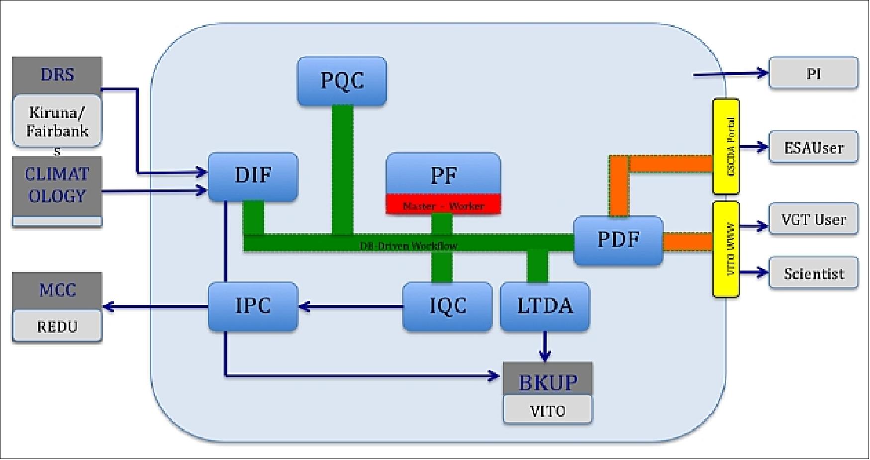
Processing | Description | Long-term | Delivered |
Raw | Communication frames, as delivered by the Data Reception Station (DRS) | Yes |
|
Level 0 | - Ingest Raw data and produces instrument packets, sorted by time, duplicated packets removed, wrong packets taken out, etc | No |
|
Level 1A | Files containing instrument data annotated with instrument and platform housekeeping as well as ancillary (position, velocity, pointing) information. All meta data needed for the following processing step towards Level 1B included. Instrument data is unprocessed, at full resolution, time-referenced. | No |
|
Level 1B | L1A plus associated geometry and geometry derived information at pixel level | Yes |
|
Level 1C | L1B that is radiometrically corrected at pixel level (unprojected TOA reflectance) | No |
|
Level 2A | L1C that is mapped and projected onto a uniform space grid, corrected for cloud, ice/snow and show artifacts (projected TOA reflectance) | Yes | P |
Level 2B | Atmospherically corrected L2A data. Bottom of atmosphere (BOA) reflectance, projected and mapped on a uniform space grid scale. | No |
|
Level 3 | Perform the compositing to provide the final User products | Yes | S1, S10 |
Some production figures, one year after launch
Since the launch of PROBA-V in early May 2013, an impressive number of images has been recorded and distributed to the user community. During the first months after launch until October 15, 2013 (commissioning): 114)
• 2.622 calibration images were taken and analyzed
• 8.345 primary images were recorded and processed
All images acquired from October 16 onwards are available to the user community. From October 16, 2013 until April 15, 2014:
• 1.392 image acquisition files were successfully downloaded from the spacecraft, transferred to the User Segment and processed
• 2.674 calibration images were taken and analyzed
• 14.021 primary images were recorded and processed (Level 1C products)
• 728 daily global composite products were generated and made available to the user community. For every day 4 different composite products are generated
• 36 decade-daily global composite products were generated and made available to the user community. For every decade, 2 different composite products are generated, one at 333m resolution and one at 1 km resolution.
The PROBA-V Radiometric IQC (Image Quality Center)
To quantify changes in environment over time, the PROBA-V measurements have to be accurate, reliable and consistent over time. It is therefore of utmost importance to monitor the stability of PROBA-V after launch and to make proper adjustments to the calibration parameters when sensor degradation is observed. The radiometric calibration requirements for PROBA-V specify 5 % absolute accuracy and 3 % relative accuracy. The IQC is in charge of the assessment of the PROBA-V performance, the analysis of the image quality and the in-flight calibration. The IQC continuously monitors the instrument calibration parameters and performance with vicarious methods in order to be able to compensate for drifts caused by systematic changes such as ageing of the instruments. To this end VITO has developed a fully operational and automated vicarious calibration facility dedicated to the routine absolute, inter-band, multi-temporal and cross-mission calibration/validation (Cal/Val) of spaceborne sensors.
The Cal/Val facility contains among others the OSCAR (Optical Sensor CAlibration with simulated Radiance) tools which exploit the reflected radiance over bright desert surfaces (main usage: absolute, cross-mission, multi-temporal), DCCs (Deep Convective Clouds), main usage: inter-band, sun glint (main usage: inter-band), atmospheric molecules or Rayleigh scattering (main usage: absolute) and even the moon (main usage: multi-temporal) (Figure 94). The advantages of this is that systematic errors inherent to one or more techniques can be dealt with, while random errors can be reduced by statistical averaging and that results can be validated independently.
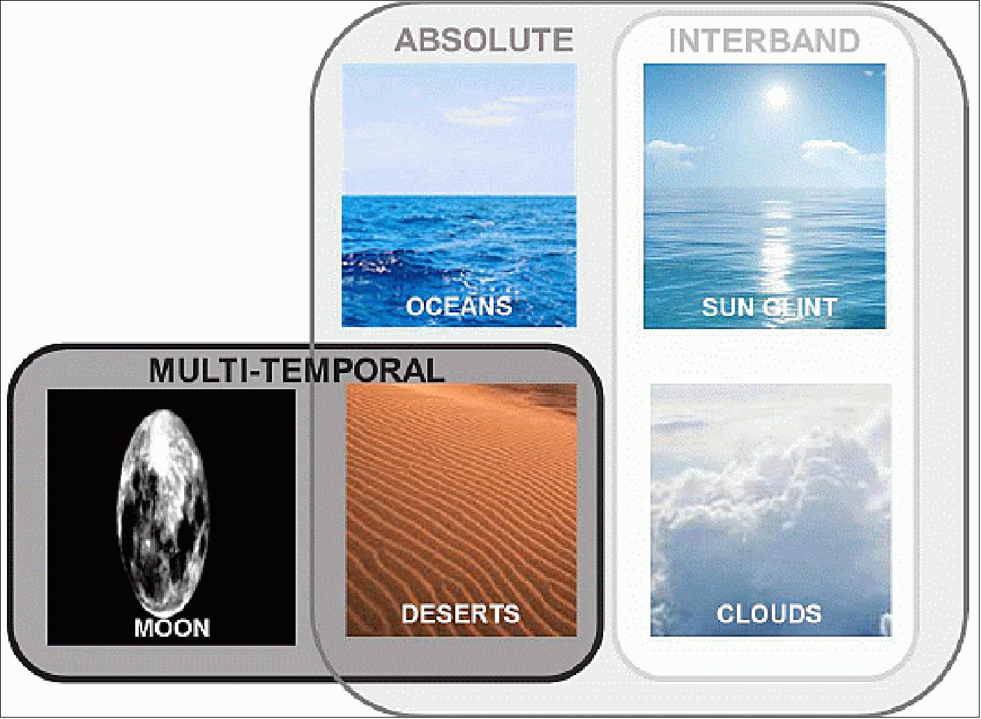
Besides the OSCAR tools, the Cal/Val facility includes tools for dark current assessment, inter-pixel (equalization) calibration and in-flight linearity verification. The dark current assessment uses images acquired during the night time over Dark Ocean in a prolonged image capture mode. Experimental in-flight linearity verification is done by changing the integration time in steps while imaging homogenous targets (Figure 95).
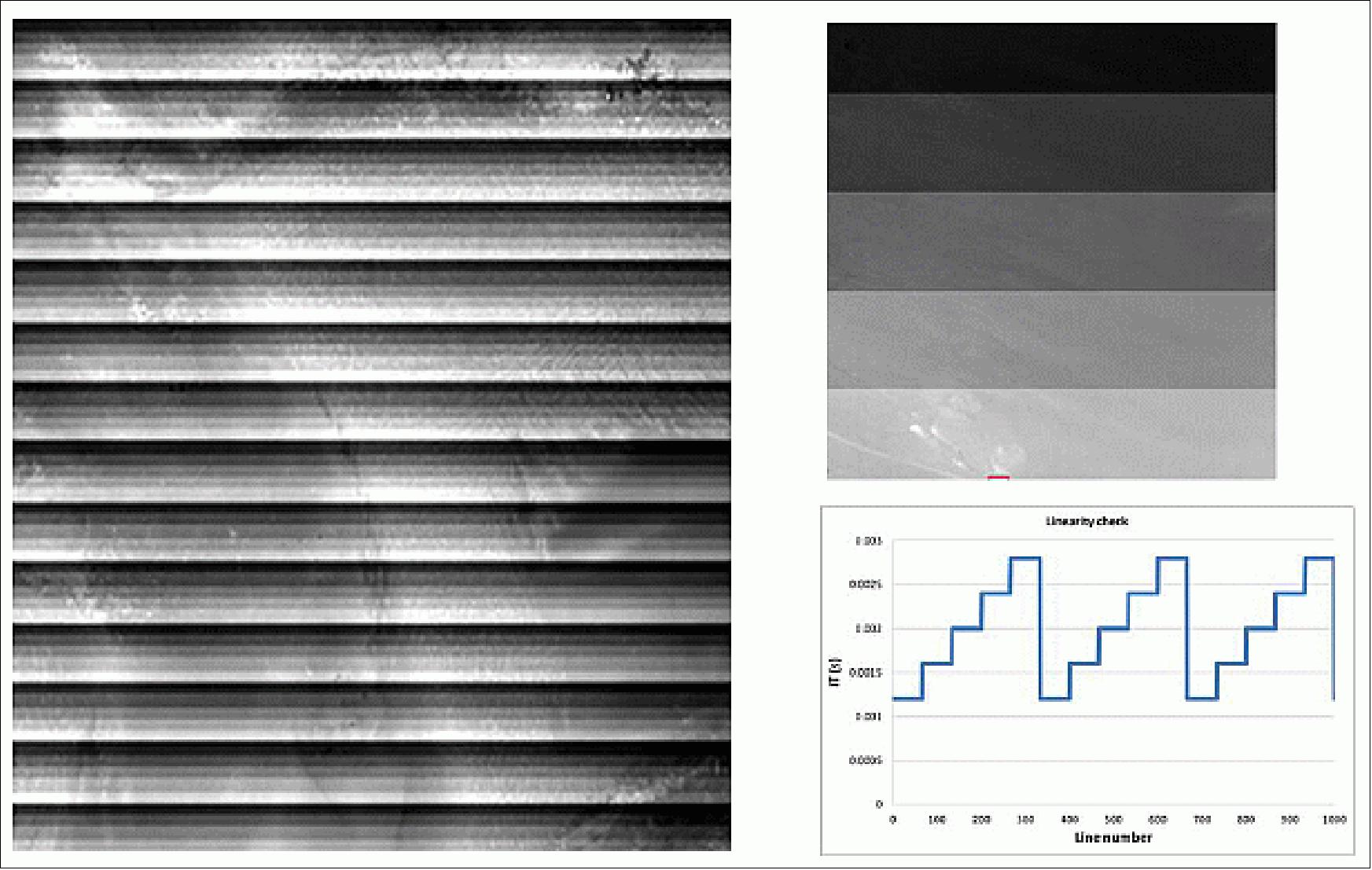
Both nominal land data (e.g. over deserts) and special calibration acquisitions (monthly lunar calibration acquisitions at a fixed phase angle, acquisitions with specific instrument settings, acquisitions over non-nominal sites, acquisitions during night) are used to evaluate the radiometric performance. The special calibrations acquisitions are verified against resources (i.e. memory and power) before they are sent to the MCC (Mission Control Center) that uploads them to the spacecraft.
The IQC is a fully automated environment. At regular intervals, the IQC workflows check whether new calibration products have been registered for processing. If this is the case, the IQC starts downloading the products (via FTP) to its own mid-term storage. Based upon the region of interest (ROI) and/or the calibration type identifier, the IQC knows which calibration method has to be executed; the IQC will then instantiate a workflow that is capable of performing the specific calibration method.
PROBA-V Radiometric Cal/Val Results
The absolute radiometric calibration accuracy is assessed with observations over the Libya-4 desert site (Figure 96, only RIGHT camera shown). The results are obtained with the absolute calibration parameters obtained, through vicarious calibration, at the end of the commissioning phase. Although some variation in the Libya-4 results between months is observed, no clear trend is visible. Compared to the summer months the number of cloud-free Libya-4 acquisitions from December to March was much lower. This results in higher uncertainty of the monthly averaged values for these months.
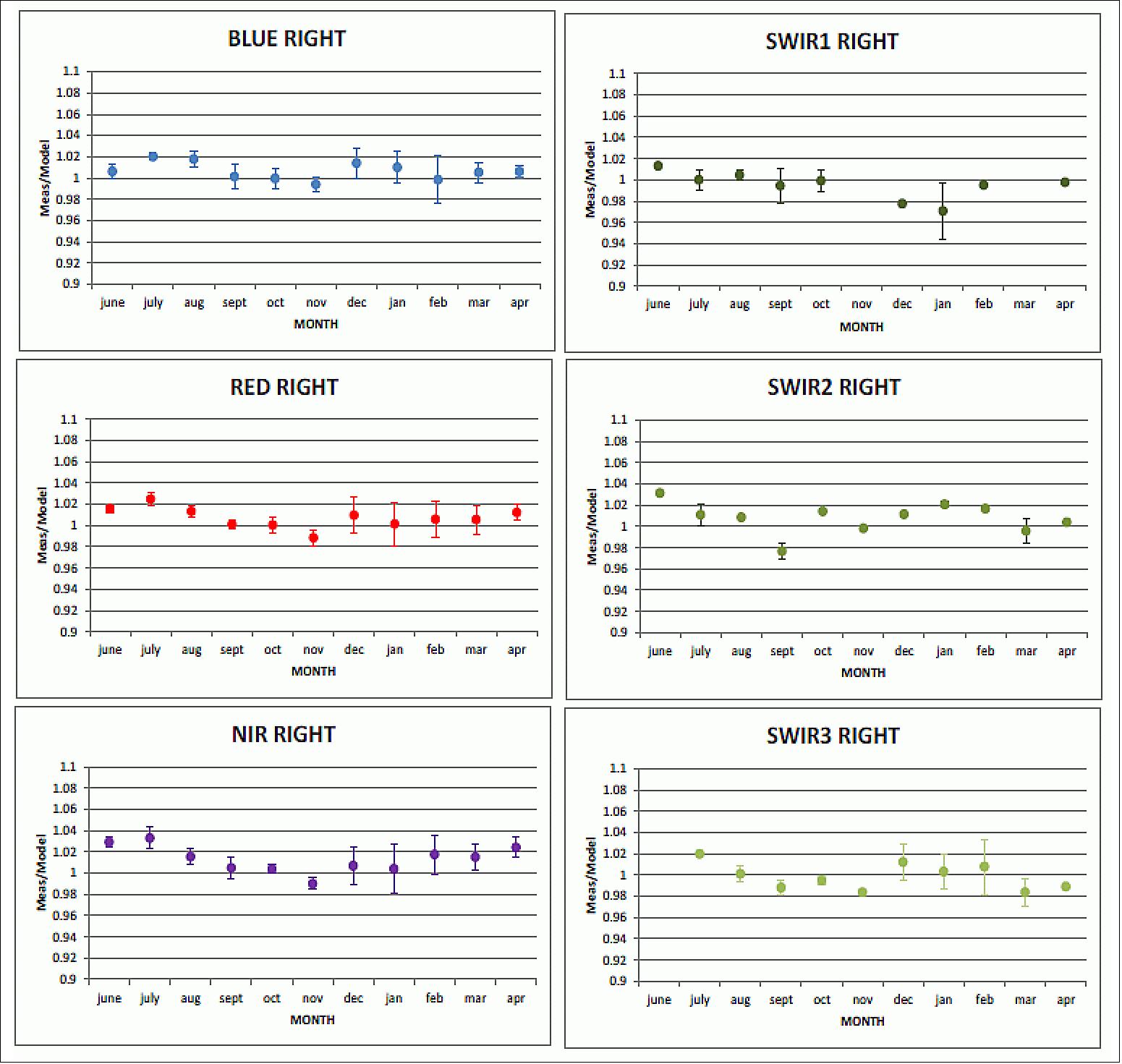
Geometric Accuracy and Stability
PROBA-V being a small platform, specific precautions, like isostatic mounting, star tracker directly mounted on optical bench, choice of material, etc....., have been taken to limit the effect of thermoelastic deformations on the Vegetation instrument that may influence the products geolocation and co-registration accuracy. The Geometric Calibration/Validation (Figure 97) service of the User Segment is implemented in order to ensure a high geometric PROBA-V products quality.
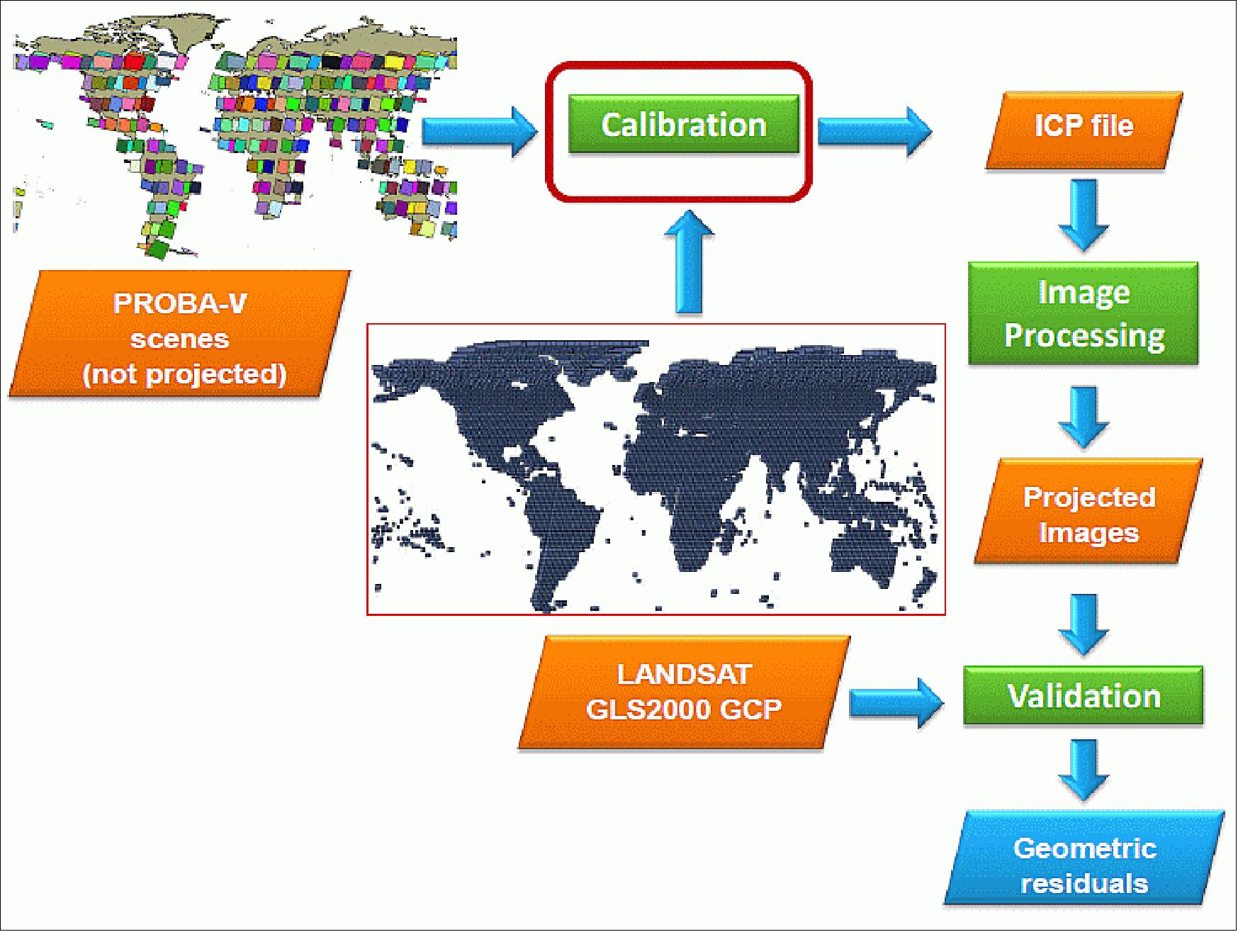
Calibration
The User Segment geometrical calibration tool continuously processes a large volume of data to estimate and monitor the Exterior Orientation parameters (boresight angles) and Interior Orientation deformations (CCD viewing direction vectors) of each camera of the PROBA-V mission.
The geometrical parameters are estimated using a large number of globally distributed GCPs (Ground Control Points), a priori extracted from the Landsat Global Land Survey GLS 2000 cloud free dataset. These estimated geometrical calibration parameters are then forwarded to the Image Processing Facility as (updated) ICP (Instrument Calibration Parameter) files.
The geometric calibration system is designed and implemented with the following hypothesis in mind:
• thermoelastic distortions change slowly, smoothly and not a lot, so that a change within an orbit can be sufficiently modelled with a 3rd order polynomial against the time since the eclipse’s exit (Time Out of Eclipse)
• seasonal change can be sufficiently modelled for a pair of months with a 1st order polynomial against sun β angle
• change across the swath can be modelled with 8th order polynomials.
One of the principal design features of the geometric calibration tool is the partitioning of the PROBA-V unprojected images in calibration datasets of a configurable length, of approximately 800 km along track. It is assumed that for these calibration datasets on the one hand, the calibration parameters remain approximately constant with respect to the camera CCD temperature or other parameters, and on the other hand, they are large enough to make a reasonable estimate of the parameters. The corrected LOS (Line Of Sight) parameters are estimated for every scene (for every camera and spectral band) and the ICP file is estimated using the collection of statistics of each scene.
The GCP database is extracted from the Landsat Global Land Survey (GLS) 2000 dataset . 115) This dataset is a collection of precision orthorectified Landsat scenes with spatial pixel resolutions of 15, 30, and 60 m for the panchromatic, reflective, and thermal bands, respectively. These data sets are comprised of all nine Landsat ETM+ spectral bands and are in a UTM (Universal Transverse Mercator) map projection. The geolocation accuracy of this product was pre specified to be below 50 m RMSE (Root Mean Square Error) globally. Independent validation of the final product, however, provides values between 19 (US) and 25 (North Eastern Africa).
Validation
In addition to the calibration step, the projected images (Level 2) generated by the Image Processing Facility are continuously checked and validated by cross correlation with the Global Landsat Survey GLS 2000 cloud free dataset (images geolocated and orthorectified with RMSE accuracy <50 m). The Landsat images were rescaled to PROBA-V products resolution by means of bilinear interpolation and to perform geometric validation at PROBA-V spatial resolution. Three types of geometric errors (absolute, inter-band and multi-temporal) are continuously monitored to ensure the highest geometric quality products at any ground location.
In summary, it can be stated, that after six months of operations and one year after launch, the PROBA-V mission is in excellent condition. The performance of the Flight Segment and the User Segment processing facility largely exceeds expectations, the products are well within requirement limits, both for radiometry and geometry, and continuity with SPOT-VGT is assured (Ref. 114).
AD-SS (ADapter and Separation System) of VERTA-1 (Vega Research, Technology and Accompaniment-1) Flight
The experience gained during the development and the qualification for the launch of the ALMASat-1 AD-SS (ADapter and Separation System) on the Vega maiden flight (launch Feb. 13, 2012), and the launch results led to a joint activity of ALMASpace with the European Space Agency aimed at the development of a wider series of adapters and separation systems based on the same design philosophy adopted for the ALMASat-1 AD-SS. 116) 117)
The target of the new series of AD-SS is the class of spacecraft up to 200 kg mass and separation velocity up to 2 m/s, with the planned development of different configurations to achieve the best trade-off between performance and costs of the AD-SS 200 model characterized by four clamping systems.
The AD-SS 200 configuration shares the same features and advantages derived from the ALMASat-1 experience:
• Tunable and calibrated separation system, allowing to vary the separation velocity from 0 up to 2 m/s
• No pyrotechnical devices involved
• Reduced refurbishing and inspection time during ground operations
• Separation switches for detachment detection included
• Standard LV/SC interfaces.
Separation system: The separation systems, previously mounted on the internal surface of the AD-SS canister (Figure 98) has been embedded in the structure, with the possibility to insert enhanced linear guides, provided by SKF, guiding the separation pads during the entire extension of the four springs, avoiding any undesired lateral forces acting on the spacecraft.

Clamping system: The clamping system for AD-SS 200 has been re-designed to reduce the volume envelope, to reduce the related stay-out zone and also to reduce the leverage of the clamping pins, therefore enhancing the robustness of the entire system. Moreover four guiding pins have been added in order to reduce the effect of degraded release conditions caused by the excessive AVUM angular rate (Figure 99).
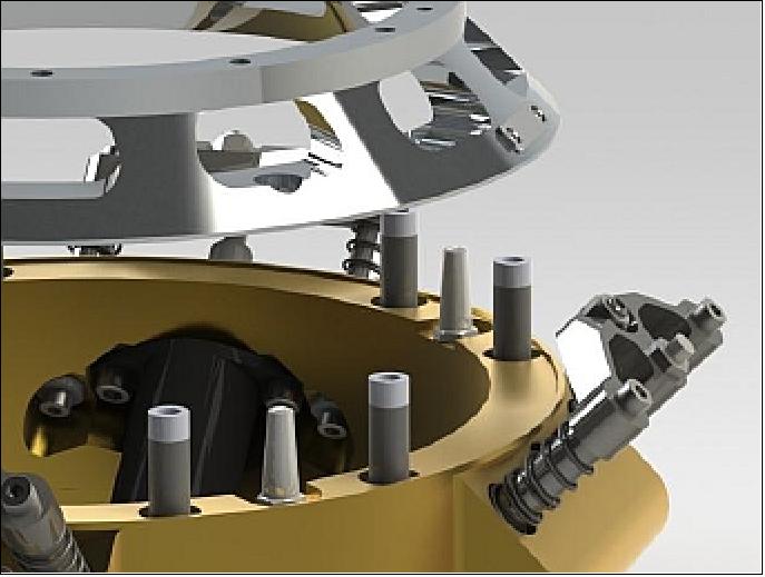
Adapter ring: As illustrated in Figure 99, the interface between the spacecraft and the AD-SS 200 is represented by an adapter ring. In order to adapt the AD-SS to a wide range of mission scenarios and spacecraft, custom adapter rings can be manufactured and installed upon customer request provided its compatibility with AD-SS 200 and spacecraft requirements. In Figure 100, the specific adapter rings for PROBA-V and TDS-1 satellites are shown.
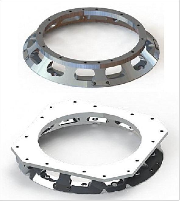
The implementation of an adapter ring as interface between the spacecraft and the AD-SS facilitate the installation of brackets for the umbilical connectors as shown in Figure 101.
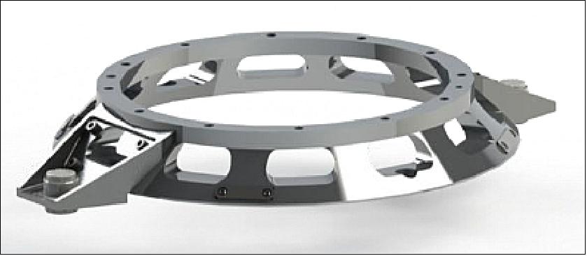
Retaining torque: The actuation philosophy selected for the release of the spacecraft from the AD-SS 200 consists in the non-simultaneous opening of the two pairs of clamps, in order to reduce the overall power needed if four NEAs were to be actuated simultaneously.
According to this solution, the first pair of clamps will be initially opened, not affecting the spacecraft positioning on the adapter; successively at the instant of the opening of the second pair of clamps, the spacecraft is left free to separate from the adapter. This solution is made possible by the applied preload and each clamp is sized to be able to guarantee the required torque to retain the spacecraft in the closed position until the last clamp is opened by the separation command.
AD-SS final design: Figure 102 shows the final design of the AD-SS 200 system. The differences with respect the previous model are the number of the clamping systems included (four instead of two) and the load capacity of NEAs included.
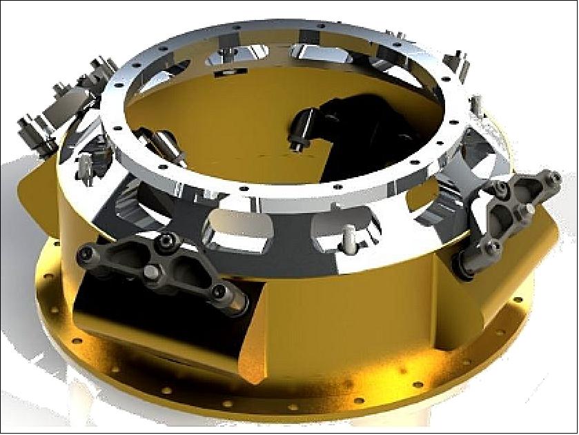
Maximum payload deployment mass of AD-SS 200 | 200 kg |
Separation velocity (@ max. P/L mass) | up to 2 m/s |
Voltage supply | 22 V |
Internal resistance | 2.4 Ohm @ 23ºC |
Current supply | 8.75 A (each NEA) |
Power supply | 770 W |
Actuation time | 20 ms @ 23ºC |
Expected scatter | ± 7 ms @ 23ºC |
Demonstrated Autonomy Concept of the PROBA-V Mission — Onboard and Onground
PROBA stands for PRoject for OnBoard Autonomy. From the very first design phases, up to the in-orbit operations, everything is oriented to achieve a maximum autonomy for the mission. This includes fully autonomous platform and payload operations, requiring only limited inputs from ground. Apart from onboard autonomy, this also includes a fully automated flight operations segment, where satellite contacts are usually executed unattended and scientific requests are passing through transparently without the need for operator presence. 118) 119)
Flight Segment Autonomy
The main drivers for the automation are to maximize the scientific return for a minimal operational cost without increasing the risk nor overall project cost. The long heritage in highly autonomous missions (PROBA-1 and PROBA-2) at QinetiQ Space provided the required expertise to accomplish this. The driving idea is that for a vegetation mission like PROBA-V, only the land masses shall be imaged.
Land-sea mask: Key feature in the design is therefore a land-sea mask. This is a digital map of the earth, clearly identifying the land and sea. Based on this map, and on the current satellite position, the onboard algorithms predict land visibility for all 3 instrument camera’s continuously (1Hz). The prediction is done for the actual satellite position and for the calculated position 10 minutes in the future. A prediction is made considering every pixel of each of the 3 imagers. As soon as a single pixel is “seeing” land, the camera prediction indicates land.
Autonomous camera switching: Based on these land predictions, the camera’s are autonomously activated and de-activated by the payload manager. Additional intelligence is added, which based on the land predictions, switches ON or OFF the specific camera’s some seconds before or after land/sea is predicted. This to cope with different platform and instrument delays and to ensures overlap of the different frequency bands within the instrument and consistent coast line acquisitions (required for geometric calibration for example).
Apart from the land-sea mask, also other parameters control the switching of the cameras. The main one is a latitude restriction, which only allows imaging between a specific northern latitude and southern latitude. These latitude restrictions are different for each of the 3 cameras. This is mainly because in the higher latitudes, the overlap between different camera’s on subsequent orbits is significant. Another parameter is the prediction whether the imaged land is in sufficient sunlight. By using this parameter, the seasonal shift of the area’s in sunlight can be handled autonomously without the need for continuous updates from ground. All of the above is carefully analyzed and designed with the PROBA-V Mission Principal Investigator (PI) during the design phase of the project.
Figure 103 provides imaging segments (color coded for right, center or left camera) plotted on top of a test land-sea mask (Central-America and the top of South-America on the left, east-Africa on the right) used for an end-2-end system validation test during ground testing.
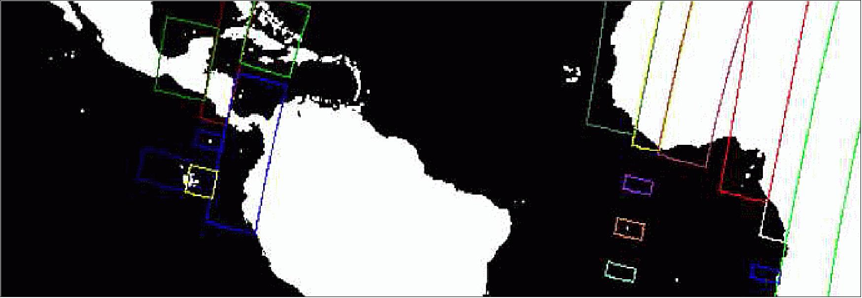
Instrument parameters: As the operations of the instrument are done fully autonomous onboard based on predictions and orbital data, the inputs from the ground for nominal acquisitions are limited to instrument settings and configurations. When the satellite performs an acquisition (during descending part of the orbit), the imaged areas have a changing light conditions. Typically, the sun will be lower at the horizon at high latitude compared to at the equator. To handle this, an additional autonomy function was added to continuously calculate the sun-zenith angle of the area which is imaged. Based on this angle, the integration time of the instrument is updated. All this is done using an integration-time table determined by the PI and uplinked to the satellite and stored onboard. As for this table, and in general, all instrument parameters (e.g. data compression settings), the PI has full authority to update it whenever required.
Fit within a PROBA context: The autonomy functions described above are absolutely required to fit a high accuracy vegetation instrument on a small and low-cost PROBA platform. Using these smart techniques, 3 main gains are achieved:
1) Reduction of the overall required power as the instrument is only ON when actually imaging. This leads to smaller solar panels, therefore allowing for the use of body-mounted arrays and a smaller battery.
2) Reduction in the required onboard data storage.
3) Reduction in the required downlink bandwidth. This allows to reduce the amount of downlink passes and therefore significantly reduces the mission operations cost.
The autonomy concepts in the previous section are controlled by a system mode manager within the onboard software. This manager is using 20+configurable parameters allowing the tuning of the autonomy in orbit.
System mode management: The system mode manager is the core of the autonomy onboard. There are 4 system modes available: safe, nominal observation, calibration and manual mode. The interaction and transitions between the modes is provided in Figure 104.
The safe mode is the default mode after boot and the fall-back mode in case of serious anomaly. It provides a robust Bdot algorithm (magnetic controller algorithm) to detumble the satellite. During the commissioning, the algorithm was updated to a 3-axis stabilized magnetic mode. This ensures that any transition to safe mode does not affect the thermal stability of the platform and more importantly of the instrument. This allows for a quick return to nominal acquisitions.
The manual mode is a mode where full flexibility is provided to the operator. It is mainly used in AIV (Assembly, Integration and Verification) and during the commissioning phase. It allows all possible attitude modes and instrument modes.
The nominal observation mode is the main mode for most of the time. In this mode, instrument activities are fully automated based on an operational scenario, which is further described in the next section.
The calibration mode is a special mode, which is used when the nominal observations need to be interrupted for a calibration activity. The entry and exit into this mode are fully autonomous and based on onboard prediction of the calibration zone to be imaged. This mode is discussed in more detail in the later section.
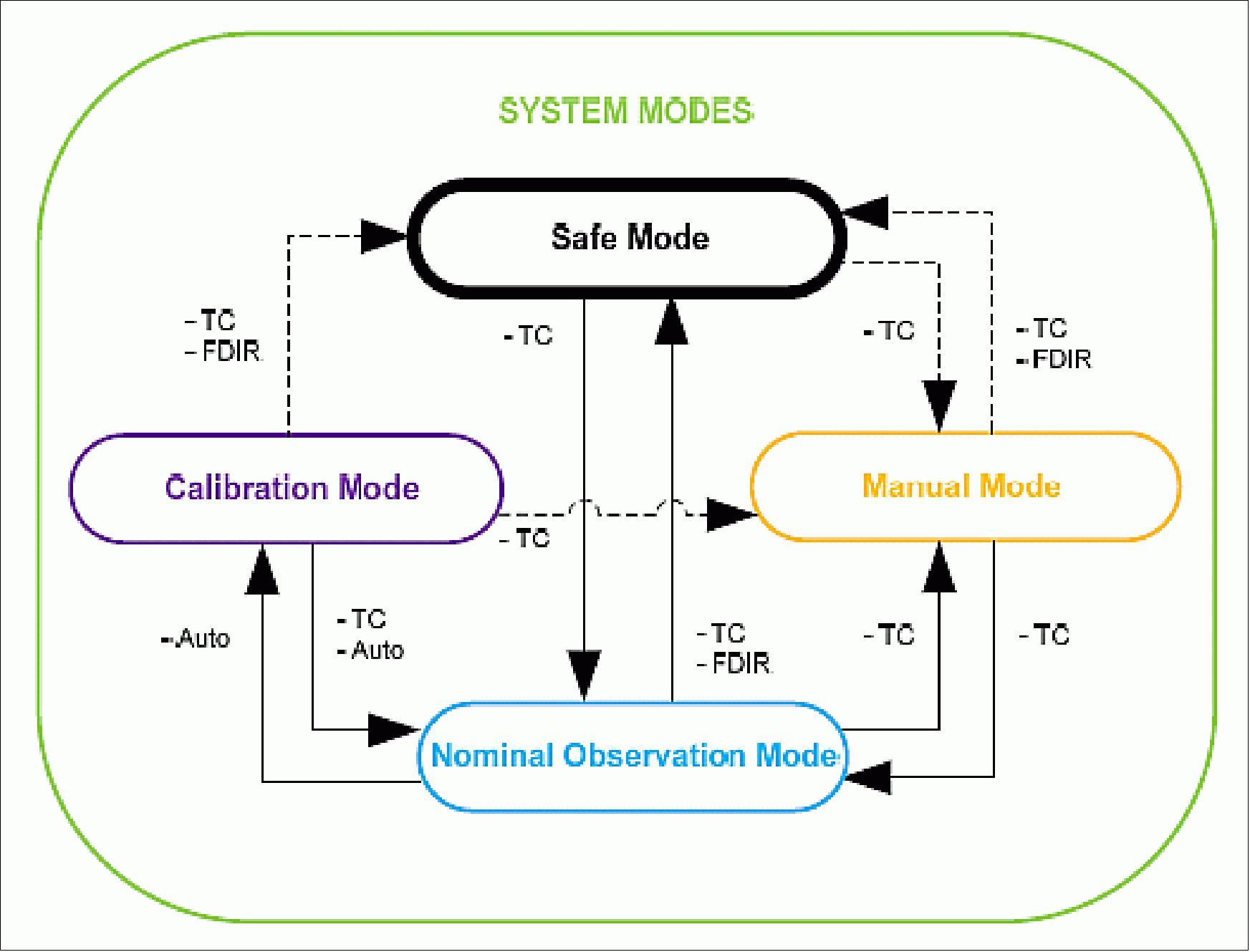
Operational scenario: When the nominal observation mode is active, the system is running the operational scenario. As opposed to nominal big science mission, this is not based on detailed timeline planning on ground, requiring the uplink of hundreds of telecommands to continue acquisitions. On PROBA-V, when the nominal observation mode is active, the operational scenario is purely done onboard, based on a reference scenario which can be tuned by a number of configurable parameters. The nominal scenario orbit has the following phases:
• Starting from north to south (descending part of the orbit), the satellite is in a geodetic attitude with yaw steering correction. It images areas with land coverage, within specific latitude restrictions and illuminated with a minimum sun angle. During this phase, the integration time is continuously updated to optimize the instrument settings wrt the light conditions of the imaged area.
• When -56º latitude is reached (latitude of Cape Horn), the satellite stops imaging and autonomously enters in a sun-bathing mode, changing the attitude to maximize the power input from the sun. During this phase, the instrument is set into idle mode.
• When entering eclipse on the ascending part of the orbit, the satellite returns to a geodetic pointing mode.
• On the exit of eclipse, the instrument is reactivated to reach thermal stability by the time the first land areas are in visibility.
• The reaction wheel momentum offloading is autonomously performed when the instrument is not imaging. The momentum offloading management is de-activated 10 s before the next imaging sequence to give some time for the platform to stabilize its attitude.
The above approach allows to activate continuous acquisitions of all scientifically interesting parts of the Earth (land defined in the land-sea mask), with a single telecommand, which is the command to enter nominal observation mode. It activates the required units, commands the correct attitude, enables the autonomous instrument operations and runs the reference scenario continuously.
This results in the following first synthesis (S30) generated about 2 months after launch (Figure 105):
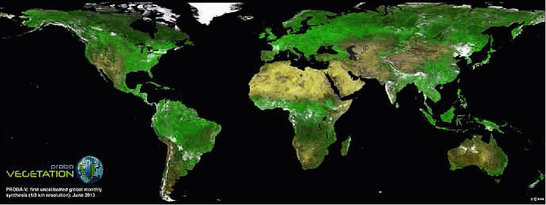
Calibration activities: The PI has the possibility to change the instrument settings used in the nominal operational scenario. The platform operators can control the trigger points like latitude restrictions, sun-bathing mode enabling/disabling, ....
The PI has also the possibility to request specific calibration activities. These are crucial for the continuous quality control of the scientific data in the User Segment (Payload Data Processing). On average 3 specific calibrations are executed every day. To limit the load on the Mission Operations Center for these regular activities, these calibrations activities are also automated. The ground processing is fully automated and is discussed further on in this paper.
Each calibration request is defined by the Image Quality Center of the PDGS, it becomes a single telecommand with the following parameters:
- Request ID
- Activation time
- De-activation time
- Latitudes and longitudes of the calibration zone (2 corners of the area)
- Satellite off-pointing angle
- Instrument configuration parameters.
The request is sent to the MOC, checked and queued for upload. When the requests are uploaded to the satellite, they are put into a specific onboard calibration queue. Based on the activation time, the calibration request is forwarded to the management software, which will predict the flyby based on the satellite position and the calibration zone specified in the request. Based on these predictions, the nominal operational scenario is interrupted automatically when the calibration zone flyby is about to occur. The system mode manager then autonomously changes the system mode to calibration mode for the duration of the calibration.
In calibration mode, first the required off-pointing is commanded (if any), followed by the reconfiguration of the instrument. For calibration activities, typically, different instrument settings are required compared to nominal observations. This is not limited to instrument settings only, but can also include changes in the compression ratios of the science data (some calibrations require uncompressed data for example).
When the entry into the zone is predicted, only the cameras which have visibility of the calibration zone are enabled. The other cameras remain in idle to optimize the power and data budgets.
When the calibration zone exit is predicted, the system mode manager returns to nominal observation mode and resumes nominal acquisitions. An onboard event is generated informing the ground about the status of the execution of the calibration request.
A special calibration request is the moon calibration. As this is not a zone on earth and the calibration is executed once every 28 days based on a specific moon phase angle, the handling of this request is slightly different from the other calibration requests. The moon requests have a separate onboard queue and the required maneuver is calculated on the ground due to the sporadic nature of the request. Figure 106 shows the result of a moon calibration.
Intelligent Failure Detection, Isolation and Recovery System-level design: The entire autonomy concept is built around the autonomous execution of the operational scenario. A main objective is also to continue the operational scenario in case of a recoverable anomaly onboard. Due to the limited (up to 14th interval), and regular unattended ground contacts, the handling of an onboard anomaly cannot be postponed until ground operator intervention.
With the heritage of PROBA-1 and PROBA-2, pioneers in the onboard FDIR (Failure Detection, Isolation and Recovery) implementation, the PROBA-V system was further optimized and tuned. The system identifies each unit or subunit in the system as a resource. Each resource has a commanded, actual and availability status. On a PROBA platform, even though it is a small platform, the redundancy concept is very extensive and robust. For all systems, a primary and redundant unit or set of units is available. In case of the star tracker for example, there is a redundant unit onboard in case of any problem with the primary unit. For the reaction wheels, of which 3 wheels are required for nominal operations, in total 4 units are available. They are integrated such that whenever a single wheel is unavailable, the remaining 3 provide the required performance without any degradation.
The cornerstone of the FDIR is the detection of anomalous behavior onboard. This is done using the standardized PUS (Packet Utilization Standard) monitoring service. Specific parameters are monitored for out of limits, sudden jumps or other abnormal behavior. The determination and tuning of the different monitoring is done throughout the AIV campaign and finalized in-orbit in the commissioning phase.
When an anomaly is detected related to a resource, the onboard software generates an event. To such an event, an action can be associated. The action is strictly dependent on the event, but globally there are 3 possible actions:
• Power cycle the resource
• Switch to the redundant resource
• Switch to system safe mode in case no redundant resource is available at that moment (software status).
The first 2 actions, allow to continue the operations without performance degradation and therefore keep the satellite in the nominal observation mode. Only in case no redundant resource is available anymore (2 subsequent anomalies on the primary and redundant resource), the system mode is changed to safe mode, which stops the image acquisitions. All the event actions can be changed by ground command. Any anomaly is reported to ground with an event and can be analyzed by the operators. Whenever the cause is clearly identified, the resource can be made available again (in case it was invalidated onboard).
This approach has allowed for continuous nominal acquisitions without interruption for months.
Flight Operations Segment Autonomy
The flight operations segment consists of the following components:
• The MOC (Mission Operations Center) in Redu (Belgium). It is developed by Spacebel (Belgium).
• The ESA S-band ground station of Redu (Belgium)
• An additional S-band ground station in Svalbard (Norway) during LEOP and commissioning phase
• The X-band ground stations of Kiruna (Sweden) and Alaska (USA).
Figure 107 provides an overview of the data flows in the PROBA-V mission. The S-band and X-band data flows are clearly separated. Platform data is transferred through S-band (up- and down-link), while all scientific data (including platform ancillary data needed for science data processing such as satellite position/attitude and on board temperatures) is transferred through X-band. On the ground, 2 main entities exist, the MOC in Redu controlling the platform and responsible for everyday operations, and the SOC (Science Operations Center) at VITO (Flemish Institute for Technological Development) that processes and distributes the science data and controls the instrument operations onboard the satellite.
Thanks to the implementation of the maximized autonomy onboard in the execution of the nominal operational scenario, calibrations and the handling of anomalies, the requirements for the mission operations can be significantly downscaled. To guarantee low cost operations, the following key features need to be supported by the flight operations segment (also called ground segment in the frame of PROBA projects). Each of them is discussed in detail further on in this section.
• Re-use the AIV system in operations
• Limited number of satellite contacts
• Autonomous contact execution
• Fast data distribution after a satellite contact
• Automated handling of scientific requests (nominal and calibrations)
• Direct data distribution from the DRS (Data Reception Station) to the SOC
• Limited number of routine tasks for the operators.
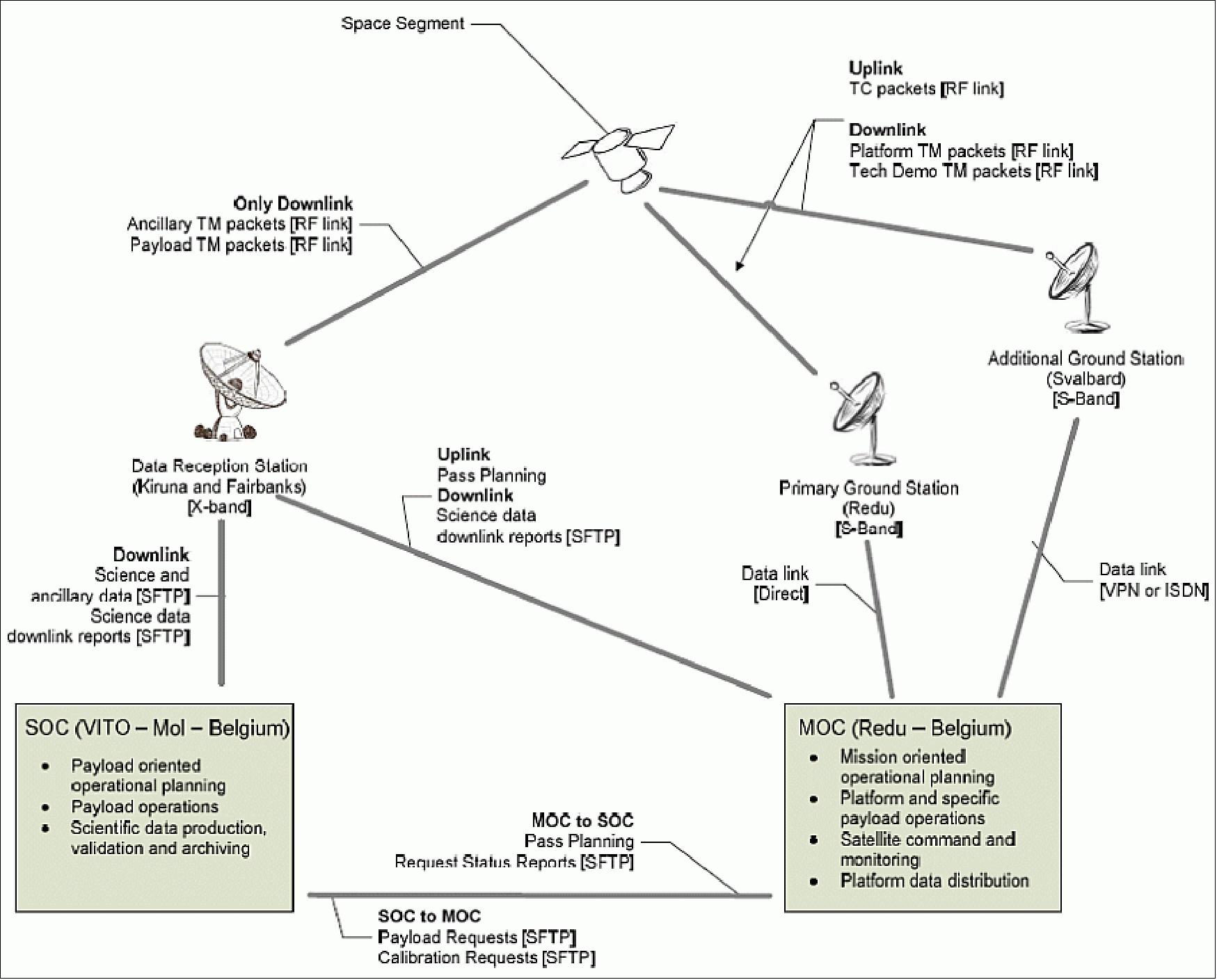
Re-use the AIV system in operations: A key feature of every PROBA project is that the ground segment software is used both as the AIV system and as the operations system. This has major benefits on nearly all levels:
• Validation of the ground segment software during the entire AIV campaign
• Re-use of AIV procedures in operations
• Re-use of the satellite database in operations
• Reduction of planning risk
• Reduction of procurement cost
• Natural transition from AIV to operations
• Limited training required for the satellite operators as the AIV teams also performs the initial operations (LEOP and commissioning).
Limited number of contacts: Due to the sophisticated FDIR system onboard, contacts can be separated by 14h for the nominal operations. This, together with an efficient platform data usage, means that for S-band (U/D), 2 or 3 contacts per day are required. As a result, a single ground station can be used, which is the ESA station in Redu (Belgium), also used for PROBA-1 and PROBA-2. Only during LEOP and the first part of the commissioning phase, a second ground station was used in S-band.
Autonomous contact execution: The key driver to have a low operational cost, while maintaining a fully operational mission is that most of the contacts can be realized unmanned. This allows to require station manning for the monitoring of the satellite only during normal office hours. This avoids shift, weekend and holiday work, which reduces significantly the operational cost. - It is clear that for this an extremely high level of automation is implemented in the Ground Segment’s functionalities.
Ground Segment Architecture: To perform a satellite contact in up- and downlink without operator attendance requires a very robust, yet flexible MOC (Mission Control Center) with an extremely powerful scripting interface. For PROBA-V the following architecture is used, heavily based on the PROBA-2 system which already provided the high level of autonomy.
MCC (Mission Control Center): The center in the architecture is the mission control center, which is a SCOS-2000 (Spacecraft Control & Operation System-2000) EGSE r3.1 system. This system provides the required TM and TC functions and display capabilities. The most powerful part of this system is, however, the TOPE scripting IF. This IF provides control and access to nearly all functions of SCOS-2000 from a script, which is vital for automation of ground activities.
Scripting: The TOPE scripts are using the TCL language extended with specific SCOS functions. From a script any kind of command defined in the satellite database can be send and checked. Access to telemetry packets and parameters is provided in a very flexible way, allowing for example that the script is notified when new telemetry packets arrive. Based on this architecture a huge collection of scripts (+500) is written, used and validated during the AIV campaign. These scripts are re-used during operations. The scripts provide the required autonomy for execution of any task. From very simple sending of a single telecommand to a complex task like scheduling a full contact planning, keeping it consistent with any changes on the ground. The scripts are individual blocks to be executed during a satellite contact.
MPS (Mission Pass Scheduler): For the autonomous execution of an entire contact, including all activities prior and after the contact phase, another application is required. The MPS provides a very simple, yet very powerful automation of the activities in a satellite contact. This organizes the execution of all contact activity scripts in a orchestrated way. It can schedule specific TOPE -or any other kind of- scripts with respect to the contact times of a satellite contact. Scripts can be running in series or in parallel. This allows to plan every activity related to a satellite contact in a dynamic flow which is automatically executed at each contact. It includes i.e. the configuration of the ground segment (baseband, antenna, ...), the acquisition of signal, the uploading of platform and payload activities and the data distribution after a contact.
With the experience from PROBA-2 and the PROBA-V AIV campaign, it allowed for the execution of a series of fully unattended satellite (up- and down-link) contacts on the evening of the LEOP of PROBA-V (~12 hours after launch). As the entire PROBA FOS can be driven by scripts, the MPS provides a very powerful interface to control these scripts and automate all activities linked to satellite contact. The application is using a pass planning file as input. Based on this it schedules and executes all satellite contacts (passes) for the PROBA-V satellite autonomously.
Apart from the default activities executed during each satellite contact, the MPS also includes a specific mechanism to include any kind of sporadic activities in the contact execution flow. This is typically used during the commissioning phase, where dedicated tests require the execution of specific command sequences. Any command sequence is still encoded in a script and is generally a full re-use of the script already used in AIV.
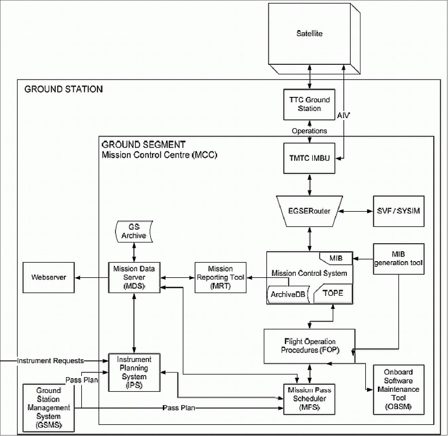
Fast data distribution after a satellite contact: During each contact a health check is run and the result is immediately distributed by email. After each satellite contact, a dedicated tool namely MRT (Mission Reporting Tool), extracts an extensive set of telemetry parameters from the MCC archive and produces subsystem specific reports, typically data since the last contact up to the current contact. Other reports (for example onboard scheduler status) are generated by specific TOPE scripts. All reports are grouped together and made available on a secured webserver within 10 minutes after a satellite contact. This is absolutely mandatory during the LEOP and commissioning phase, but also during nominal operations to allow remote access to all platform data by operators and support teams.
In addition to the distribution of the data through email and webserver, a PROBA-V mobile application is also available for iOS and Android. This allows interactive navigation through the data and provides access anywhere, anytime from a smartphone or tablet.
Automated handling of scientific requests: The onboard autonomy provides the autonomous handling of instrument requests. They can be used for:
• Changing default instrument settings
• Change specific tables like for example the integration time – sun-zenith angle correlation table
• Acquisition of a specific calibration zone with dedicated instrument settings or even a platform off-pointing.
The autonomous handling is also included in the flight operations segment. The key goal is to provide the SOC should with near-realtime access to the scientific instrument onboard the satellite. The access is only limited by contact times.
To achieve this, during the design phase, the scope and variety of the instrument requests is discussed with ESA (customer) and the PI. A well-defined instrument request template is defined and checked against the boundary conditions (power and data budgets, maximum off-pointing, etc. ...). The template is encoded as an XML file and on both MOC and SOC side, a specific application handles the instrument requests.
The SOC generates the request and perform different checks before it is sent to the MOC. On reception of an instrument request at the MOC, a syntax and consistency check is executed after which the request is prepared for upload at the next satellite contact. This requires no operator intervention and can therefore be executed during nights or weekends. At the next contact, the request is uploaded and later on executed onboard. The final status of the request is downlinked again to the flight operations center, which forwards any change of the instrument request status to the SOC with a dedicated XML message. This ensures that the SOC has full visibility over the complete lifecycle of an instrument request at all times.
This approach does not only provide maximum automation, it also ensures maximum instrument accessibility for the PI and therefore maximum scientific return. The solution is both cost effective and optimizes the overall performance of the system.
Direct data distribution from the data reception station to the SOC: The distribution of the scientific data from the DRS (Data Reception Station) to the SOC is also highly automated and requires no intervention from an operator. The DRS receives the raw data in X-band and publishes this data on a sFTP server in an agreed raw format. When new data is available, the SOC picks up the data directly from the sFTP for processing. The MOC automatically receives a report after each contact and forwards this report by email to the operators and support teams.
Limited number of routine tasks for the operators: Due to the powerful scripting capabilities of the flight operations segment, any routine operator tasks can be further automated. This is mainly done during the commissioning and operations phase. Doing this, the operators can use their time in a much more efficient way.
References
1) J. Michaud, F. Tinto, J. M. Biffi, P. Etcheto, L. Perraud, C. Thiebaut, V. Albouys, A. Guerin, X. Passot, P. Henry, P. Maisongrande, J. Foliard, J.-L. Legal, S. Martinez-Alcade, “Study for a VEGETATION Follow on Mission onto PROBA-2 Bus,” Proceedings of the IAA Symposium on Small Satellite Systems and Services (4S), Rhodes, Greece, May 26-30, 2008, ESA SP-660, August 2008,
2) Lieven Bydekerke, Koen Meuleman, “The potential use of small satellite for crop monitoring in emerging economies,” Proceedings of the IAA Symposium on Small Satellite Systems and Services (4S), Rhodes, Greece, May 26-30, 2008, ESA SP-660, August 2008
3) Jo Bermyn, “PROBA spacecraft family - small mission solutions for emerging applications,” Proceedings of the 59th IAC (International Astronautical Congress), Glasgow, Scotland, UK, Sept. 29 to Oct. 3, 2008, IAC-08.B4.4.B4
4) “PROBA-V, National contribution to augment the output of GMES,” April 10, 2008, URL: https://web.archive.org/web/20131108090013/http://www.vrind.be:80/nl/docs/workshop080410/Presentatie%20Verhaert.pdf
5) Erwin Goor, “SPOT-Vegetation and PROBA-V Interoperability,” GSCB (Ground Segment Coordination Body) Workshop, ESA/ESRIN, Frascati, Italy, June 18-19, 2009
6) “ESA Industrial Policy Committee, GSTP General Support Technology Program),” ESA/IPC(2008)29, March 20, 2008, URL: http://www.ffg.at/getdownload.php?id=2491
7) M. Claessens, D. Vrancken, K. Mellab, S. Santandrea, “PROBA-V: a Multispectral Earth Observation Mission Based on Small Satellite Technology,” Proceedings of the Symposium on Small Satellite Systems and Services (4S), Funchal, Madeira, Portugal, May 31-June 4, 2010
8) Guillaume Huby, Richard P. Kleihorst, Karim Mellab, Lénaïc Grignard, “PROBA-V, a vegetation satellite,” Proceedings of the SPIE Remote Sensing Conference, Toulouse, France, Vol. 7826, 'Sensors, Systems, and Next-Generation Satellites XIV,' edited by Roland Meynart, Steven P. Neeck, Haruhisa Shimoda, Sept. 20-23, 2010, doi: 10.1117/12.864543
9) Michael Francois, “PROBA Vegetation,” International User Committee #2, Project Status, Brussels, BELSPO (Belgian Federal Science Policy Office), 22-23 February 2011, URL: http://probav-iuc.org
/assets/201102/ESA_MF_ProjectStatus.pdf?symfony=ee68c49bb35c3b0befdf3498b10957f2
10) Stefano Santandrea, “PROBA-V Mission,” 8th IAA (International Academy of Astronautics) Symposium on Small Satellites for Earth Observation, Berlin, Germany, April 4-8, 2011, paper: IAA-B8-0202, URL of presentation: http://media.dlr.de:8080/erez4
/erez?cmd=get&src=os/IAA/archiv8/Presentations/IAA-B8-0202-1.pdf
11) “PROBA Vegetation,” IUC (International Users Committee), URL: http://probav-iuc.org/
12) Davy Vrancken, Dennis Gerrits, Karim Mellab, Stefano Santandrea, “PROBA-V: A Multi-Spectral Earth Observation Mission Based on a PROBA Platform – Status Update,” Proceedings of the 4S (Small Satellites Systems and Services) Symposium, Portoroz, Slovenia, June 4-8, 2012
13) “PROBA-V Overview,” ESA, URL: http://www.esa.int/Our_Activities/Technology/Proba_Missions/Overview2
14) Sean Blair, “ V For Vegetation - The mission of Proba-V,” ESA Bulletin No 153, Feb. 2013, pp: 10-21, URL: http://proba-v.vgt.vito.be/sites/default/files
/ESA%20Bulletin%20_%20PROBA-V%20article%20_%2002.2013.pdf
15) PROBA-V brochure, ESA, URL: http://esamultimedia.esa.int/multimedia/publications/BR-310/
16) Stijn Ilsen, Dennis Gerrits, Joris Naudet, Peter Holsters, Karim Mellab, Stefano Santandrea, Etienne Tilmans, Christian Baijot, Thomas Laroche, Alain Verheyden, ”PROBA autonomous platform operations: challenges in a changing operational context,” Proceedings of the 4S (Small Satellites, System & Services) Symposium, Valletta, Malta, May 30-June 3, 2016
17) Luca Maresi, Matteo Taccola , Wouter Moelans, Vincent Moreau, Jan Vermeiren, “Compact Optical Payload for Daily Survey of Vegetation from Small Satellites,” Proceedings of the 23nd Annual AIAA/USU Conference on Small Satellites, Logan, UT, USA, Aug. 10-13, 2009, SSC09-III-9
18) Michael Francois, “PROBA-V Mission,” ESA, July 5, 2013, URL: http://probing.vegetation.be/sites/default/files/pdf
/dag2/1010-Michael%20Francios-Proba-V%20Probing%20Vegetation.pdf
19) “Wide-eyed Proba-V will track global vegetation daily,” ESA, May 4, 2010, URL: http://www.esa.int/SPECIALS/Proba/SEML40KPO8G_0.html
20) “About PROBA-V, ESA, Nov. 3, 2010, URL: http://www.esa.int/esaMI/Proba/SEM9FS4PVFG_0.html
21) “Go-ahead for the new Belgian satellite PROBA-V,” 2008, URL: http://www.vrind.be/en/docs/Press%20release/Verhaert_PROBA_V_en.pdf
22) Davy Vrancken, “Introduction to the PROBA platform,” PCOT (Programa Catalàd’Observació de la Terra) Workshop, Barcelona, Spain, April 18, 2008, URL: http://www.pcot.cat
/web/pcotcontent/docs/jornades/20080418_noves_plataformes/verhaert.pdf
23) B. Paijmans, D. Vranken, D. Gerrits, K. Mellab, S. Santandrea, “Proba V : A multi-spectral Earth observation mission based on a PROBA platform,” Proceedings of the 63rd IAC (International Astronautical Congress), Naples, Italy, Oct. 1-5, 2012, IAC-12-B4.4.7
24) Davy Vrancken, Dennis Gerrits, Karim Mellab, Stefano Santandrea, “PROBA-V: The Global Vegetation Tracker,” Proceedings of the 64th International Astronautical Congress (IAC 2013), Beijing, China, Sept. 23-27, 2013, paper: IAC-13-B4.4.5
25) K. Mellab, S. Santandrea, M. Francois, D. Vrancken, D. Gerrits, A. Barnes, P. Nieminen, P. Willemsen, S. Hernandez, A. Owens, T. Delovski, M. Cyamukungu, C. Granja, “PROBA‐V: An Operational and Technology Demonstration Mission – Results after Commissioning and One Year of In‐orbit Exploitation,” Proceedings of the 4S (Small Satellites Systems and Services) Symposium, Port Petro, Majorca Island, Spain, May 26-30, 2014
26) J. Côté, A. St-Amour, B. Paijmans, A. Kron, J.-L. Beaupellet, J. de Lafontaine, “Attitude and Orbit Control Software: Recent Innovations for Upcoming Missions,” Proceedings of ASTRO 2010, 15th CASI (Canadian Aeronautics and Space Institute) Conference, Toronto, Canada, May 4-6, 2010
27) J. Côté, A. St-Amour, B. Paijmans, J. Naudet, S. Santandrea, J. de Lafontaine, “PROBA-V Attitude and Orbit Control System: Integration and System-Level Test Results,” Proceedings of GNC 2011, 8th International ESA Conference on Guidance, Navigation & Control Systems, Carlsbad (Karlovy Vary), Czech Republic, June 5-10, 2011
28) A. St-Amour, J-F. Hamel, G. Mercier, J. Naudet, S. Santandrea, J. de Lafontaine, “In‐Flight Results of the PROBA‐V Three‐Axis Pointing Safe Magnetic Mode,” Proceedings of the 4S (Small Satellites Systems and Services) Symposium, Port Petro, Majorca Island, Spain, May 26-30, 2014
29) E. Peragin, H. Guillon, K. Melab, Y. Richard, T.; Dehaene, G. Richard, M. Kouybeissi, D. Belot, H. Diez, O. Alvarez, J.-L. Guillet, “Small Platform Telemetry Downloading, from S to X Band,” Proceedings of the Symposium on Small Satellite Systems and Services (4S), Funchal, Madeira, Portugal, May 31-June 4, 2010
30) Yves Richard, Miguel-Angel Fernandez, Jean-Luc Issler, Hervre Guillon, Peter Holters, Andre Barnes, Karim Mellab, “In‐flight Experience and Results of the PROBA‐V Low Cost X‐Band HDR‐TM Transmitter,” Proceedings of the 4S (Small Satellites Systems and Services) Symposium, Port Petro, Majorca Island, Spain, May 26-30, 2014
31) ”Gallium nitride helping link Proba-V to Earth,” ESA, June 2015, URL: http://m.esa.int/Our_Activities/Space_Engineering_Technology
/Proba_Missions/Gallium_nitride_helping_link_Proba-V_to_Earth
32) “Testing time for PROBA-V, ESA's Global Vegetation Tracker,” ESA, January 14, 2013, URL: http://www.esa.int/Our_Activities/Technology
/Proba_Missions/Testing_time_for_Proba-V_ESA_s_global_vegetation_tracker
33) “Vega poised for commercial launches,” ESA, April 26, 2013, URL: http://www.esa.int/Our_Activities/Launchers/Vega_poised_for_commercial_launches
34) “ESA's Vega launcher scores new success with PROBA-V,” ESA press release No 12-2013, May 7, 2013, URL: http://www.esa.int/For_Media/Press_Releases
/ESA_s_Vega_launcher_scores_new_success_with_Proba-V
35) http://www.esa.int/Our_Activities/Technology/Proba_Missions/About_Proba-V
36) “ESA's Vega launcher scores new success with PROBA-V,” ESA, Prees Release No 12-2013, May 7, 2013, URL: http://www.esa.int/Our_Activities/Launchers
/ESA_S_Vega_launcher_scores_new_success_with_Proba-V
37) Stephen Clark, “Vietnamese satellite booked for second Vega launch,” Spaceflight Now, January 4, 2013, URL: http://www.spaceflightnow.com/news/n1301/04vnredsat1a/#.UOwGWpGQk9Y
38) “Arianespace to launch VNREDSat-1A built by Astrium for Vietnam,” Space Travel, January 08,2013, URL: http://www.space-travel.com/reports
/Arianespace_to_launch_VNREDSat_1A_built_by_Astrium_for_Vietnam_999.html
39) ”PROBA-V passes the torch,” ESA, 9 July 2020, URL: https://www.esa.int/ESA_Multimedia/Images/2020/07/Proba-V_passes_the_torch
40) ”Ending global plant tracking, Proba-V assigned new focus,” ESA Enabling & Support, 20 April 2020, URL: http://www.esa.int/Enabling_Support/Space_Engineering_Technology
/Proba_Missions/Ending_global_plant_tracking_Proba-V_assigned_new_focus
41) ”PROBA-V images smoke plumes from Borneo,” ESA Technology image of the week, 21 October 2019, URL: http://www.esa.int/spaceinimages/Images
/2019/10/Proba-V_images_smoke_plumes_from_Borneo
42) ”Recovering burn scars in Argentina,” ESA, Technology image of the week, 24 July 2019, URL: http://www.esa.int/spaceinimages/Images/2019/07/Recovering_burn_scars_in_Argentina
43) ”City by the mountains,” ESA Technology image of the week, Populous Santiago in Chile, set to host the next UN Climate Change Conference, viewed by ESA’s Proba-V minisatellite, 12 June 2019, URL: http://www.esa.int/spaceinimages/Images/2019/06/Santiago_Chile_viewed_by_Proba-V
44) ”New Zealand’s South Island imaged by Proba-V,” ESA, 15 May 2019, URL: http://www.esa.int/spaceinimages/Images/2019/05/New_Zealand_s_South_Island_imaged_by_Proba-V
45) ”Proba-V view of Galápagos,” ESA, Technology image of the week, 27 March 2019, URL: http://m.esa.int/spaceinimages/Images/2019/03/Proba-V_view_of_Galapagos
46) ”Catching the world in a box,” ESA, 15 February 2019, URL: http://m.esa.int/Our_Activities
/Space_Engineering_Technology/Proba_Missions/Catching_the_world_in_a_box
47) ”The dessert that ate the sea,” Technology image of the week: ESA’s Proba-V minisatellite views efforts to stabilize a newly formed desert and salvage the shrinking Aral Sea,9 January, 2019, URL: http://m.esa.int/spaceinimages/Images/2019/01/Proba-V_view_of_Aral_Sea
48) ”PROBA-V images the Yucatán peninsula,” ESA, Technology image of the week, 7 November 2018, URL: http://m.esa.int/spaceinimages/Images/2018/11/Proba-V_images_the_Yucatan_peninsula
49) ”Proba-V Antarctic survey,” ESA, 04 May 2018, URL: http://m.esa.int/spaceinimages/Images/2018/05/Proba-V_Antarctic_survey
50) ”Proba-V image of South Korea,” ESA, Technology image of the week: ESA’s Proba-V minisatellite surveys the site of the Winter Olympics, 14 Feb. 2018, URL: http://m.esa.int/spaceinimages/Images/2018/02/Proba-V_image_of_South_Korea
51) ”Lake Chany imaged by PROBA-V,” ESA, 20 Dec. 2017, URL: http://m.esa.int/spaceinimages/Images/2017/12/Lake_Chany_imaged_by_Proba-V
52) ”PROBA-V images Atlas Mountains,” ESA technology image of the week, 10 Nov. 2017, URL: http://m.esa.int/spaceinimages/Images/2017/11/Proba-V_images_Atlas_mountains
53) ”PROBA-V images Salar de Uyuni,” ESA technology image of the week, 20 Sept. 2017, URL: http://m.esa.int/spaceinimages/Images/2017/09/Proba-V_images_Salar_de_Uyuni
54) ”PROBA-V monitors African Sahel,” ESA, July 26, 2017, URL: http://m.esa.int/spaceinimages/Images/2017/07/Proba-V_monitors_African_Sahel
55) ”PROBA-V images Portuguese forest fire,” ESA, June 21, 2017, URL: http://m.esa.int/Our_Activities/Space_Engineering_Technology
/Proba_Missions/Proba-V_images_Portuguese_forest_fire
56) ”PROBA-V images Mokpo in South Korea,” ESA, Technology image of the week, May 19, 2017, URL: http://m.esa.int/spaceinimages/Images/2017/05/Proba-V_images_Mokpo_in_South_Korea
57) ”Norwegian fjords imaged by PROBA-V,” ESA, March 29, 2017, URL: http://m.esa.int/spaceinimages/Images/2017/03/Norwegian_fjords_imaged_by_Proba-V
58) ”Flinders Ranges, Australia,” ESA, Feb. 21, 2017, URL: [web source no longer avaliable]
59) ”PROBA-V images Mount Everest,” ESA, Technology image of the week, Dec. 15, 2016, URL: http://m.esa.int/spaceinimages/Images/2016/12/Proba-V_images_Mount_Everest
60) ”Dots in the landscape: PROBA-V images desert irrigation,” ESA, Technology image of the week, Oct. 19, 2016, URL: http://m.esa.int/spaceinimages/Images/2016/10/Proba-V_images_desert_irrigation
61) Carlos Granja, Stepan Polansky, Stanislav Pospisil, Alan Owens, Karim Mellab, ”Mapping the Space Radiation Environment in LEO orbit by the SATRAM Timepix Payload on board the PROBA-V satellite,” Proceedings of the Living Planet Symposium 2016, Prague, Czech Republic, May 9-13, 2016 (ESA SP-740, August 2016)
62) ”PROBA-V views Great Salt Lake,” ESA image of the week, Aug. 26, 2016, URL: http://m.esa.int/spaceinimages/Images/2016/08/Proba-V_views_Great_Salt_Lake
63) ”PROBA-V view of Hawaii,” ESA/BELSPO, image of the week, released on April 6, 2016, URL: http://www.esa.int/spaceinimages/Images/2016/03/Proba-V_view_of_Hawaii
64) PROBA-V eyes Bolivia's vanishing lake,” ESA, Feb. 8, 2016, URL: http://www.esa.int/Our_Activities/Space_Engineering_Technology
/Proba_Missions/Proba-V_eyes_Bolivia_s_vanishing_lake
65) ”PROBA-V tracks Lake Poopó evaporation,” ESA, Feb. 4, 2016, URL: http://www.esa.int/spaceinimages/Images/2016/02/Proba-V_tracks_Lake_Poopo_evaporation
66) ”MinisatelliteMonitors Massive Australian Smoke Plume,” EIJ (Earth Imaging Journal), Jan. 25, 2016, URL: http://eijournal.com/slider-images/minisatellite-monitors-massive-australian-smoke-plume
67) Bianca Hoersch, ”Mission status PROBA-V & update on Sentinel-2,” PROBA-V Symposium, Ghent, Belgium, 26 - 28 January 2016, URL of presentations: http://congrexprojects.com/2016-events/16c01
68) ”Easier and faster access to all PROBA-V products,” ESA, PROBA-V News, Dec. 15, 2015, URL: https://web.archive.org/web/20161216001952/https://earth.esa.int/web/guest/missions/esa-operational-eo-missions/proba-v/news/-/article/easier-and-faster-access-to-all-proba-v-products
69) ”Kilimanjaro imaged by PROBA-V,” ESA image of the week, October 21, 2015, URL: http://www.esa.int/spaceinimages/Images/2015/10/Kilimanjaro_imaged_by_Proba-V
70) Wouter Dierckx, Iskander Benhadj, Sindy Sterckx, Stefan Adriaensen, Else Swinnen, Erwin Wolters, Dennis Clarijs, Tom Van Roey, Jan Dries, Bart Deronde, “PROBA-V's new assets for global monitoring of vegetation growth,” Proceedings of the IGARSS (International Geoscience and Remote Sensing Symposium) 2015, Milan, Italy, July 26-31, 2015
71) “PROBA-V detecting aircraft,” ESA, May 1, 2015, URL: http://www.esa.int/spaceinimages/Images/2015/05/Proba-V_detecting_aircraft
72) “PROBA-V views Drakensberg mountains,” ESA image of the week, May 6, 2015, URL: http://www.esa.int/spaceinimages/Images/2015/05/Proba-V_views_Drakensberg_mountains
73) “Scanning Earth, saving lives,” ESA, March 6, 2015, URL: http://www.esa.int/Our_Activities
/Space_Engineering_Technology/TTP2/Scanning_Earth_saving_lives
74) “Lake Frome seen by PROBA-V,” ESA 'image of the week', March 4, 2015, URL: http://www.esa.int/spaceinimages/Images/2015/03/Lake_Frome_seen_by_Proba-V
75) J. Loicq, L. Clermon, W. Dierckx, T. Van Achteren,Y. Stockman, “A 100 m ground resolution global daily coverage Earth Observation mission,” Proceedings of the ICSO (International Conference on Space Optics), Tenerife, Canary Islands, Spain, Oct. 7-10, 2014, URL: http://congrexprojects.com/Custom/ICSO/2014/Papers/2.%20Wednesday%208%20October
/Session%208C%20Imagers%20-%20Radiometers%20-%20Land%20Surface/1.66011_Loicq.pdf
76) “PROBA-V images Indonesian volcano,” ESA, Dec. 4, 2014, URL: http://www.esa.int/spaceinimages/Images/2014/12/Proba-V_images_Indonesian_volcano
77) “PROBA-V image of western Brazil,” ESA, Oct. 16, 2014, URL: http://www.esa.int
/spaceinimages/Images/2014/10/Proba-V_image_of_western_Brazil
78) The Figure image is featured in ESA's 'Our week through the lens' service, ESA, June 2-6, 2014, URL: http://www.esa.int/Highlights/Week_In_Images_02_06_June_2014
79) T. Delovski, K. Werner, T. Rawlik, J. Behrens, J. Bredemeyer,R. Wendel, “ADS-B over Satellite — The world’s first ADS-B receiver in Space,” Proceedings of the 4S (Small Satellites Systems and Services) Symposium, Port Petro, Majorca Island, Spain, May 26-30, 2014
80) “After 16 years of successful operations, SPOT-VEGETATION ready to hand over the torch to PROBA-V,” VITO, April 30, 2014, URL: https://www.vito.be/EN/HomepageAdmin/Home
/Nieuws/Nieuwsberichten/Pages/news_spotvegetation_proba-v_apr2014.aspx
81) “Aral Sea,” ESA, May 28, 2014, URL: http://www.esa.int/spaceinimages/Images/2014/05/Aral_Sea
82) “Happy Birthday PROBA-V,” ESA, May 7, 2014, URL: http://www.esa.int
/Our_Activities/Observing_the_Earth/Proba-V/Highlights/Happy_Birthday_Proba-V
83) “PROBA-V’s Olympic view, ESA, Feb. 17, 2014, URL: http://www.esa.int/spaceinimages/Images/2014/02/Proba-V_s_Olympic_view
84) Information was provided by Frédéric Teston, Head of Systems & Cost Engineering Division, ESA
85) “PROBA-V data ready for use,” ESA, Dec. 03, 2013, URL: http://www.esa.int
/Our_Activities/Observing_the_Earth/Proba-V/Proba-V_data_ready_for_use
86) “Probing vegetation across the globe,” ESA, July 10, 2013, URL: http://www.esa.int
/Our_Activities/Observing_the_Earth/Probing_vegetation_across_the_globe
87) Earth from Space: Probing Mesopotamia,” June 28, 2013, URL: http://www.esa.int/Our_Activities/Observing_the_Earth/Earth_from_Space_Probing_Mesopotamia
88) “ADS-B over satellite – first aircraft tracking from space,” DLR, June 13, 2013, URL: http://www.dlr.de/dlr/en/desktopdefault.aspx/tabid-10081/151_read-7318/year-all/#gallery/11231
89) PROBA-V tracking aircraft in flight from orbit,” ESA, June 13, 2013, URL: http://www.esa.int/Our_Activities/Technology
/Proba_Missions/Proba-V_tracking_aircraft_in_flight_from_orbit
90) “PROBA-V opens its eyes,” ESA, May 17, 2013, URL: http://www.esa.int/Our_Activities/Technology/Proba_Missions/Proba-V_opens_its_eyes
91) Jorg Versluys, Dave Kendall, Wouter Moelans, Dominique Mollet, Piet Holbrouck, Davy Vrancken, Matteo Taccola, Michael François, “The Vegetation Instrument: A Small Scale High Performance Earth Observation Instrument,” Proceedings of the 4S (Small Satellites Systems and Services) Symposium, Portoroz, Slovenia, June 4-8, 2012
92) “Wide-eyed Proba-V will track global vegetation daily,” May 4, 2010, URL: http://www.esa.int/esaCP/SEMOYZJPO8G_index_0.html
93) A. Mazzoli, P. Holbrouck, Y. Houbrechts, L. Maresi, Y. Stockman, M. Taccola, J. Versluys, “Baffles Design of the PROBA-V Wide FOV TMA,” ICSO 2010 (International Conference on Space Optics), Rhodes Island, Greece, Oct. 4-8, 2010, URL: http://congrex.nl/ICSO/Papers/Session%202b/Mazzoli.pdf
94) Alessandro Zuccaro Marchi, Matteo Taccola, Michael François, Ignacio Torralba, Alessandro Zuccaro Marchi, Didier Beguin, Jorg Versluys, Yvan Stockman, Ignacio Torralba, Ronald Kassel, “PROBA V Multispectral Imager: Status,” Proceedings of the ICSO (International Conference on Space Optics), Ajaccio, Corse, France, Oct. 9-12, 2012, URL: http://congrex.nl/icso/2012/papers/FP_ICSO-138.pdf
95) L. De Vos , W. Moelans, J. Versluys, V. Moreau, J. F. Jamoye, Jan Vermeiren, L. Maresi, M. Taccola, “The Vegetation Instrument for the PROBA-V mission,” Proceedings of the 7th IAA Symposium on Small Satellites for Earth Observation, Berlin, Germany, May 4-7, 2009, paper: IAA-B7-0303, URL of presentation: http://media.dlr.de:8080/erez4/erez?cmd=get&src=os
/IAA/archiv7/Presentations/0303%5FBerlin%5Favi.pdf
96) S. Grabarnik, M. Taccola, L. Maresi, V. Moreau, L. de Vos, J. Versluys, G. Gubbels, “Compact Multispectral and Hyperspectral Imagers based on a Wide Field of View TMA,” ICSO 2010 (International Conference on Space Optics), Rhodes Island, Greece, Oct. 4-8, 2010, URL: http://www.rsp-technology.com/ICSO-2010-Surface-roughness%201nm.pdf
97) A. Mazzolli, P. Holbrouck, Y. Houbrechts, L. Maresi, Y. Stockman, M. Taccola, J. Versluys, “Baffles Design of the PROBA-V Wide FOV TMA,” ICSO 2010 (International Conference on Space Optics), Rhodes Island, Greece, Oct. 4-8, 2010, URL: http://congrex.nl/icso/Papers/Session%202b/Mazzoli.pdf
98) Jonas Bentell, Koen van der Zanden, Thierry Colin, Siegfried Herftijd, Patrick Merken, Jan Vermeiren, “A Comparative Study of the MSI and Proba-V Linear Arrays under the influence of Radiation,” Proceedings of the 4S (Small Satellites Systems and Services) Symposium, Portoroz, Slovenia, June 4-8, 2012
99) Jorg Versluys, Piet Holbrouck, Avi Blasberger, Dave Kendall( Michiel Vullings, Luca Maresi, “A Passive Thermal Control System on the Vegetation Instrument,” Proceedings of the Symposium on Small Satellite Systems and Services (4S), Funchal, Madeira, Portugal, May 31-June 4, 2010
100) Björn Osterloh, Harald Michalik, Christian Dierker, Sebastian Brandt, Boris Penné, Peter Holsters, “A highly compact Data Handling Unit with real time data compression for the PROBA-V Program,” Proceedings of the 9th IAA Symposium on Small Satellites for Earth Observation, Berlin, Germany, April 8-12, 2013, paper: IAA-B9-1111P
101) S. Grabarnik, V. Moreau, C. De Clercq, L. de Vos, B. Delarué, L. Maresi, “Compact Hyperspectral Imager Breadboard,” Proceedings of the Symposium on Small Satellite Systems and Services (4S), Funchal, Madeira, Portugal, May 31-June 4, 2010
102) V. Moreau, S. Grabarnik, L. Maresi , S. Delalieux, L. de Vos , B. Delauré, C. De Clercq, W. Dierckx, E. Knaeps, B. Michiels, “Compact Hyperspectral Imager Breadboard,” 8th IAA (International Academy of Astronautics) Symposium on Small Satellites for Earth Observation, Berlin, Germany, April 4-8, 2011
103) S. Adriaensen, I. Benhadj, G. Duhoux, W. Dierckx, J. Dries, W. Heyns, R. Kleihorst, S. Livens, K. Nackaerts, I. Reusen, S. Sterckx, T. Van Achteren, J. Everaerts, “Building a Calibration and Validation System for the PROBA-V Satellite Mission,” ISPRS International Calibration and Orientation Workshop, EuroCOW 2010, Feb. 10-12, 2010, Castelldefels, Spain, URL: http://www.isprs.org
/proceedings/XXXVIII/Eurocow2010/euroCOW2010_files/papers/08.pdf
104) Stefano Mica, Luca Galli, Geert Duhoux, Stefan Livens, Veljko Jovanovic, Alessandra Giustiniani, Jan C. Dries, Joe Zender, Stefano Santandrea, “PROBA-V Geometric Calibration,” Proceedings of IGARSS (International Geoscience and Remote Sensing Symposium), Munich, Germany, July 22-27, 2012
105) Sindy Sterckx, Stefan Adriaensen, Stefan Livens, Wouter Dierckx, Ils Reusen, “PROBA-V IQC: Radiometric Cal/Val activities after launch,” June 22, 2011, URL: http://calvalportal.ceos.org/cvp/c/document_library
/get_file?p_l_id=154792&folderId=154592&name=DLFE-2830.pdf
106) “PROBA-V equipped for radiation census of space,” ESA, June 17, 2011, URL: http://www.esa.int/esaMI/Proba/SEMJKCRHPOG_1.html
107) “Proba-V will put European gallium nitride to its first space test,” ESA, Oct. 20, 2010, URL: http://www.esa.int/esaMI/Proba/SEM7QUYOBFG_0.html
108) “Improved gallium nitride recipe could spark space communication revolution,” ESA, URL: http://www.esa.int/SPECIALS/Technology/SEMJ1X9BWUF_0.html
109) Jörg Behrens, “Tracking aircraft from space,” DLR, May 3, 2013, URL: http://www.dlr.de/dlr
/en/desktopdefault.aspx/tabid-10081/151_read-6967/year-all/#gallery/9760
110) “Total Ionization Dose Test, DLR ADS-B Receiver,” DLR Institute of Space Systems, March 17, 2011, URL: http://joinspace.org:8080/scheduler/testplan/20086/AoS-PL-TID-DLR-DRAFT.pdf
111) “SES Techcom To Support Aircraft Tracking From Space,” GPS Daily, May 15, 2013, URL: http://www.gpsdaily.com/reports
/SES_Techcom_To_Support_Aircraft_Tracking_From_Space_999.html
112) Erwin Goor, “SPOT-Vegetation and PROBA-V Interoperability,” 3rd GSCB (Ground Segment Coordination Body) Workshop, 2012, ESA/ESRIN, Frascati, Italy, June 6-7, 2012, URL: http://earth.esa.int/gscb/papers/2012/24-SPOT-VEGETATION_and_PROBA-V_Interoperability.pdf
113) Erwin Goor, Tom Van Roey, “PROBA-V Product Distribution Facility (PDF),” PROBA-V IUC (International User Committee) meeting, BELSPO, Brussels, Belgium, Feb. 18, 2011, URL: http://probav-iuc.org/assets/201102/PROBA-V_PDF.pdf?symfony=ac641a47762fed1225eb58f6af577012
114) Jan Dries, Sindy Sterckx, Iskander Benhadj, Stefan Adriaensen, Tom Van Roey, Karim Mellab, Joe Zender, “PROBA-V in-flight results, one year after launch,” Proceedings of the 4S (Small Satellites Systems and Services) Symposium, Port Petro, Majorca Island, Spain, May 26-30, 2014
115) http://glcf.umd.edu/data/gls/
116) Alberto Corbelli, Davide Bruzzi, Paolo Tortora, Marco Bocciarelli, Benoit Geffroy, “The Adapter and Separation Systems Series for the Vega Launch Vehicle,” Proceedings of the 4S (Small Satellites Systems and Services) Symposium, Portoroz, Slovenia, June 4-8, 2012
117) Davide Bruzzi, Alberto Corbelli, Paolo Tortora, Marco Bocciarelli, Benoit Geffroy, “The adapter and separation systems series for the VEGA launch vehicle,” Proceedings of the 63rd IAC (International Astronautical Congress), Naples, Italy, Oct. 1-5, 2012, paper: IAC-12-B4.5.10
118) Stijn Ilsen, Dennis Gerrits, Davy Vrancken, Joris Naudet, Karim Mellab, Stefano Santandrea, Thomas Laroche, Alain Verheyden, “PROBA-V: The example of onboard and onground autonomy,” Proceedings of the AIAA/USU Conference on Small Satellites, Logan, Utah, USA, August 2-7, 2014, paper: SSC14-XII-8, URL: http://digitalcommons.usu.edu/cgi/viewcontent.cgi?article=3079&context=smallsat
119) Stijn Ilsen, Dennis Gerrits, Joris Naudet, Peter Holsters, Stefano Santandrea, Karim Mellab, Etienne Tilmans, Christian Baijot, ThomasLaroche, Alain Verheyden, ”PROBA autonomous platform operations: challenges in a changing operational context,” Proceedings of the 14th International Conference on Space Operations (SpaceOps 2016), Daejeon, Korea, May 16-20, 2016, URL: http://arc.aiaa.org/doi/book/10.2514/MSPOPS16
120) OSCAR, “PROBA-V-CC”, URL: https://space.oscar.wmo.int/satellites/view/proba_v_cc
121) Spacewatch.Global, “Aerospacelab launches PROBA-VCC Satellite”, October 9, 2023, URL: https://spacewatch.global/2023/10/aerospacelab-launches-proba-v-cc-satellite/
122) Aerospacelab, “PVCC MISSION & PVCC SATELLITE”, September 9, 2022, URL: https://www.belspo.be/belspo/space/documents/2022-01_ANN2.pdf
123) Nanosats database, “Proba-V Companion CubeSat (PVCC, Proba V-CC)”, November 4, 2023, URL: https://www.nanosats.eu/sat/proba-v-companion-cubesat
124) VITO, “PROBA-V’s Companion Launched Successfully”, October 9, 2023, URL: https://vito.be/en/news/proba-v%E2%80%99s-companion-satellite-launched-successfully
125) SpaceWatch, “Aerospacelab Launches PROBA V-CC Satellite”, October 9, 2023, URL: https://spacewatch.global/2023/10/aerospacelab-launches-proba-v-cc-satellite/
Overview Spacecraft Launch Mission Status Sensor Complement Payloads Ground Segment
References Back to top