QuakeSat
EO
Mission complete
SESS
Quick facts
Overview
| Mission type | EO |
| Agency | SESS |
| Mission status | Mission complete |
| Launch date | 30 Jun 2003 |
| End of life date | 31 Dec 2004 |
| CEOS EO Handbook | See QuakeSat summary |
QuakeSat
QuakeSat is a research nanosatellite, a collaboration of SSDL (Space Systems Development Laboratory) at Stanford University, Stanford, CA, and of the QuakeFinder Team of Palo Alto, CA. The overall objective is earthquake signature detection.
QuakeSat's primary scientific mission is to detect, record, and downlink ELF (Extremely Low Frequency) magnetic signal data, which may lead to groundbreaking techniques to predict earthquake activity. According to theory, fracturing bedrock along the fault lines creates the ELF magnetic waves. These signatures radiate from the earthquake hypocenter region (several tens of km2), through the Earth (5-80 km), through the atmosphere to the ionosphere (100-200 km), and are propagated up the Earth's magnetic field lines to satellite altitude. 1) 2) 3) 4) 5) 6)
Spacecraft
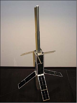
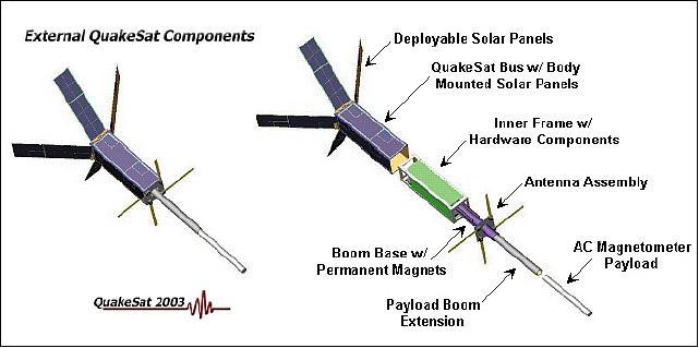
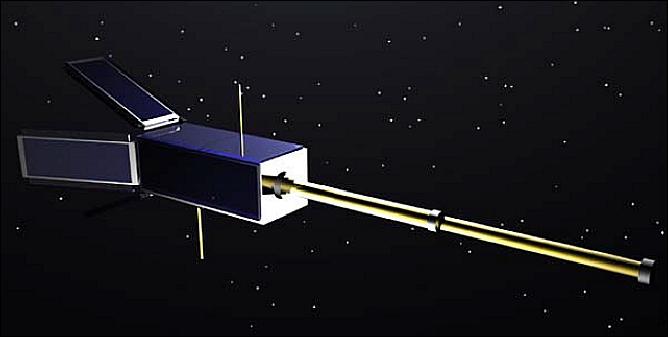
The nanosatellite design is based on the CubeSat concept where each CubeSat is of 10 cm side length. QuakeSat is in fact a triple CubeSat to provide a large enough size to include a 30 cm long magnetometer that extends on a telescoping boom. QuakeSat is a prime example of CubeSat technology, which utilizes COTS (Commercially-Off-The-Shelf) components for scientific experiments and payloads. QuakeSat measures slightly more than 10 cm x 10 cm x 30 cm (stacking of three CubeSat payloads) with a total mass of about 4.5 kg. The outer structure of QuakeSat (consisting of 6061 aluminum) fits inside the P-POD launch tube.
The spacecraft subsystems are:
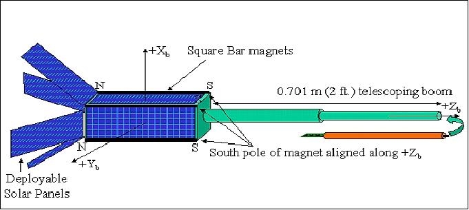
ADCS (Attitude Determination and Control Subsystem): Permanent magnets are used for attitude control to keep the magnetometer aligned close to the Earth's magnetic field. Four magnets are being used, each of size 6.35 mm x 6.35 mm x 102 mm and a mass of 0.224 kg. By aligning the magnets along the boom axis constraints QuakeSat to fly nearly parallel to the magnetic field lines as the S/C rotates twice per orbit about an axis perpendicular to the boom (+Zb) axis. The QuakeSat boom is nadir pointing over the North Pole and zenith pointing over the South Pole. Two hysteresis rods are used for damping. Solar array current measurements are beiing used to determine the attitude with respect to the sun. From this input an attitude estimation is being done to determine how close the magnetometer sensor is aligned to the Earth's magnetic field and how much of an ELF signal is measured.
EPS (Electric Power Subsystem): The EPS consists of a power source, power storage and a power regulator. The power source consists of 12 solar arrays: four body-mounted panels and four are double-sided deployable wings. Two Li-ion batteries are being used.
C&DH (Command and Data Handling) subsystem: The C&DH consists of a Prometheus CPU module with Ethernet and data acquisition all on a single board (64 MByte memory and 128 MByte of flash disk). A Linux operating system is being used. A major function of C&DH is to monitor all spacecraft functions (there are 48 housekeeping sensors, etc.). Onboard storage for one day of science data is provided.
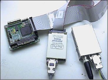
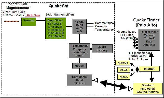
OBC (On-Board Computer): QuakeSat uses a Prometheus PC/104 CPU of Diamond Systems with a built in 16 channel, 16-bit A/D converter. Use of a Diamond Systems Linux OS (Operating System). The simple software architecture is outlined as follows:
• Device driver: hardware timers, payload board controller
• Executive program: receive a command, send a response (1 packet up/down)
• Worker program (reads in a time-tagged sequence of commands and executes them). This allowed multi-day planned collections.
• Beacon program (send beacons: alive health/status).
• File upload/download standalone programs PFS/PFR (with integrated hole management to fill in missed packets).
• Heartbeat generation program to tell the watchdog board all is working.

RF communications: The UHF band (436.675 MHz, 20 kHz bandwidth) is being used for uplink and downlink communications (half duplex, data rate = 9.6 kbit/s). The AX.25 protocol, standard in the ham radio community, is being used for the communication protocol. The two major components of the Communications subsystem are the BayPac BP-96A modem and the Tekk T-Net mini 960 radio.
Orbit | SSO (Sun-Synchronous Orbit) dawn-dusk, mean altitude about 820 km |
Spacecraft dimensions | 150 cm x 80 cm x 80 cm (deployed); 35 cm x 11 cm x 11 cm (stowed) |
Spacecraft mass | 4.5 kg |
Power (solar arrays) | 12 solar panels (4 body fixed and 4 double sided deployable) |
Power (batteries) | 2 Li-ion batteries (3.0Ahr total) (Failed open circuit on Jan. 24 and Jan. 28, 2004, respectively) |
Power load | 3.6 W continuous |
Power load (transmitter) | 1-1.4 W, depending on bus voltage |
Communication | 436.675 MHz half duplex, 9600 baud |
Attitude control | Passive magnetic stabilization, (likely not maintaining pre-launched planned attitude) |
Attitude determination | 12 solar array currents primary, IR and temperature sensors as secondary. (However, Mux with primary channels failed at launch.) |
OBC | Prometheus PC-104, down clocked to 66MHz, 32 RAM |
Data quantization | 16 channel, 16bits up to 3000 samples/sec |
Onboard storage | 128 MB Flash, up to 64 MB available for data collection |
Launch: The first multiple launch CubeSat mission, involving some 6 Cubesats as secondary payloads, and a primary commercial payload, took place June 30, 2003. The launch vehicle was Rockot KS of Eurockot Launch Services (Bremen, Germany) from the launch site Plesetsk, Russia with the following secondary payloads:
• XI (X-factor Investigator) of the University of Tokyo, Japan
• CUTE-I of Tokyo Institute of Technology (TITech), Tokyo, Japan
• CanX-1 of the University of Toronto, Toronto, Canada
• AAUSat of Aalborg University, Aalborg, Denmark
• DTUSat of the Technical University of Denmark, Lyngby, Denmark
• QuakeSat of Stanford University, Stanford, CA, USA (3U CubeSat with a total mass of about 4.5 kg)
The primary payloads on this mission were:
• MIMOSA of the Czech Astronomical Institute, Ondrejov, Czech Republic with a launch mass of 66 kg
• MOST (Microvariability and Oscillations of Stars) of CSA (Canadian Space Agency), Saint-Hubert, Quebec with a launch mass of 51 kg
• Monitor E mock-up of GKNPT Khrunichev Space Center, Moscow, Russia with a mass of 700 kg. The payload Monitor-E remains on the upper stage of the launch vehicle.
The deployment strategy of Rockot KS employed MOM (Multiple Orbit Mission), based on the multiple re-ignition capability of its Breeze upper stage. Initially, the MIMOSA payload was being deployed into an elliptical orbit of 820 km x 320 km. After another impulse maneuver of the main engine, Breeze then deployed MOST, followed by the CubeSats into a sun-synchronous orbit of 820 km near-circular altitude at pre-determined intervals. The Monitor-E mock-up will remain on the upper stage and will de-orbit together with Breeze into the atmosphere.
The CubeSat launch was coordinated by UTIAS/SFL (University of Toronto, Institute for Aerospace studies/Space Flight Laboratory) for CanX-1, AAUSat and DTUSat. A single P-POD of CalPoly was used for XI and CUTE-I as well as for CanX-1, AAUSat and DTUSat. This integrated system was dubbed NLS-1 (Nanosatellite Launch System-1). The second launch system, NLS-2, consisted of QuakeSat and its own dedicated P-POD.
CubeSat orbits: Near-circular sun-synchronous dawn-dusk orbit, mean altitude = 820 km, inclination = 98.73º, local equator crossing time at 6:00 and 18:00.
Mission Status
• QuakeSat was designed to fly for one year, but the mission ended up lasting for 1 ½ years to the end of December 2004. 7)
• The spacecraft and its instruments are operational as of Sept. 2004. A total of nearly 2000 magnetometer collections were made of all modes, primarily in the mode 2 configuration (10 to 150 Hz), roughly 500 MB raw binary uncompressed data. The areas targeted were primarily, 1) likely earthquake regions, hoping to catch a signal before an event and 2) significant post earthquake collections in the region surrounding the earthquake. In addition, over a 100 collections were made looking for lightning strikes and several global 1-10 Hz surveys were made (Ref. 1).
- Within the approximately 2000 collections made to date (Sept. 2004), with approximately 6000 “signals” detected. Within that signal set, there were approximately 25 “signal types” identified. The majority of these were self-induced satellite noise (power supplies, battery charge controllers, modem, transmitter, heartbeat, and a 100 Hz CPU generated clock). After these were manually identified and removed, natural signals were also identified (lightning-induced whistlers, polar hiss, elevated noise during the Oct. 28-Nov. 2 solar storms). The remaining signal set was categorized as “unexplained ELF” signals. Particular interest was given to a series of wideband ELF noise bursts with energy between 10 Hz and 150 Hz, and lasted from 2 s to 20 s.
- QuakeSat did detect ELF bursts over 8 earthquake areas in 12 months. These bursts may be unique to earthquake areas, but it is important to collect more data using different and more sensitive instruments such as those on DEMETER to confirm these findings (Ref. 9).
• June 15, 2004: The QuakeSat mission is quickly approaching it's one year point. Although the satellite has now begun encountering periodic reboots due to brief eclipsing of the sun due to the earth in its sun synchronous orbit, QuakeSat continues to make payload data collection and data downloads.
• Jan. 20, 2004: After nearly 6 months in low earth orbit, QuakeSat lost both of its primary batteries within 4 days of each other. This may have been due to the result of the high battery temperatures that have reached upwards of 120 degrees Fahrenheit. QuakeSat is again in a sun synchronous orbit that is currently in the sun all day, and everyday. At this temperature it is possible that the electrolyte had “baked out” since the batteries were not sealed beyond the normal factory packaging. 8)
- Nevertheless, QuakeSat's power subsystem is rather robust, and it is currently operating off of pure solar power. This has resulted in a significant degradation in mission performance, however, we are still collecting and downloading nearly one-third the amount of data that we have been operating at thus far over the past six months.
- The spacecraft had successfully collected over 1500 data files until January 2004 when the unexpected loss of its Li-ion batteries reduced the operational capacity of the mission. The solar panels continued to provide limited power in the dawn-dusk orbit, but reduced power reserves make downloads more difficult now. The collection strategy was to collect signals over areas of high earthquake probability by selectively operating the magnetometer as the spacecraft crossed the “target areas” (Ref. 9).
• Earthquake signals: Broadband signals were seen immediately following the August 21 2003, 7.2M South Island NZ quake, the December 22, 2003 6.5M San Simeon CA quake, and the December 1, 2003 6.0M Kazakhstan-Xinjiang Border Region earthquake (Ref. 3).
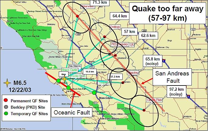
- Preliminary results of the satellite collections showed unique signals prior to and after the San Simeon quake, as well as several other large world-wide quakes. Ground collections were inconclusive since the closest 4 sensors of the available 35 sensors were located more than 60 km and 2 parallel fault traces away from the San Simeon quake epicenter. 9)

• Sept. 12, 2003: QuakeSat is 2 ½ months in orbit and continues to work very well. The orbit has precessed so that the satellite is in the sun 100% of the time. Temperatures have climbed a few degrees with the maximums for the CPU and 5 volt power supply climbing to 145-150ºF range, far enough from the 185ºF limit. 10)
- C&DH: The CPU has had several "upsets" over the last few weeks. Some of the problems were due to an interrupt contention which caused the counters to stop being serviced (translation — the satellite stops taking data). Several others upsets may have been caused by high energy particles disturbing computer instructions and locking up the computer. The "Watchdog Timer", a separate PIC processor, worked great, detected the lack of a CPU "heartbeat", and reset the computer. This causes the clock to reset to zero, so a clock reset must occur to synchronize GMT to the CPU clock before starting to take data again. This causes a bit of data loss, but this is not a big problem, the process is refined.
- Payload data: There are MANY signals present — just sorting through them is a major effort. There were many noise signals in the original data because the magnetometer is so sensitive, it picks up EVERYTHING--including subtle things inside the spacecraft!
• July 5, 2003: The project achieved a major milestone in on orbit operations by successfully beginning to download both payload magnetometer and housekeeping data (magnetometer data shown below). Overall in first week in orbit, QuakeSat is operating well, and appears to be in good health. 11)
- EPS: All 12 solar panels appear to be working based on intermittent solar array current data taken. The two battery packs appear to stay fully charged in the sunlight, and show nominal discharges during eclipse periods. In addition, the ±5 volt power supplies are nominal.
- C&DH: The 1.2 W Tekk radio with 9600 baud and AX.25 packet system is working well. However, since QuakeSat is tumbling with a period of approximately 300 seconds, sporadic antenna nulls are observed as the satellite spins, resulting in reduced download efficiency. The transmitter on the satellite appears to have a slightly higher center frequency than the nominal transmit and receive frequency of 436.675 MHz. Temperatures may be responsible for moving this up to 436.677 MHz, though further analysis will be conducted.
- ACS: QuakeSat is passively stabilized with four Alinco permanent magnets and one Carpenter 80 hysteresis rod along the magnetometer axis. Telemetry from an IR earth sensor and several temperature points show a tumble (or nutation) period of 300 s (slowed from 128 s at launch on June 30, 2003). The loss of the continual solar panel current data will make it very difficult to estimate the satellite’s coarse attitude and spin/nutation rate.
Sensor Complement
Magnetometer
The spacecraft features a single axis magnetometer and a small E-field dipole antenna. The objective is the detection of ELF signatures. The strategy used to detect the small magnetic field measurements (0.5 to 1000 Hz) relies on the use of a very sensitive AC magnetometer. The ELF sensor is a single axis, search coil (induction) type magnetometer with multiple frequency bands. The magnetometer features:
• Two 25,000 turn coaxial coils + a calibration coil
• Low noise preamp with negative resistance circuit (GSFC)
• Sensitivity: 10 pT noise floor (theoretical)
• Dynamic range: 80-100 db (low and high gain mode) 16 bit A/D conversion
QuakeSat records ELF magnetic field data in the 1-1000 Hz range in 4 bands, one band at a time. This choice of bandwidth was influenced by Cosmos 1809 which had detected signals in the 140 Hz channel, and Aureol-3, which had detected similar signals during 1989 and the early 1990’s. The QuakeSat band was expanded to 10-1000 Hz, and collected raw time series to determine if there were any unique time-series signatures that could lead to more focused collection strategies in future missions.
Band (or mode) | Description | Collection limit |
Band 1 (mode 1) | 0.5 - 10 Hz narrow band B field @ 50 samples/s | 100 min continuous |
Band 2 (mode 2) | 10 - 150 Hz wide band B field @ 500 samples/s | 10 min continuous |
Band 3 (mode 3) | 10 - 1000 Hz wide band B field @ 3000 sample/s | 100 sec continuous |
Band 4 (mode 4) | 140 Hz [127-153 Hz pass band (E and B field)] @ 500 samples/s | 30 sec continuous |
The magnetometer is 30.5 cm long and 1.9 cm in diameter, it extents into a telescoping boom. All bands are sampled 2-3 times/s at their highest frequency, band 4 is excepted with a sampling rate of 1/s. The segmented (telescoping) boom has a total length of 701 mm. Total mass (boom + sensor) = 0.822 kg.
The sampling strategy for the magnetometer data maps the world into 5º x 5º grids of latitude and longitude. The 5º resolution was derived to allow the sensor to be turned on and calibrated prior to passing over an area of high earthquake activity. Also by using a 5° grid, the selected earthquake areas results in a 15% duty cycle for the payload, resulting in dramatically reduced power requirements.
The position of QuakeSat on the world map is determined through TLE (Two Line Element) sets provided by NORAD and a ground-based propagator. The TLE data sets are estimated to give an error in position of approximately < 10 km. The determination of QuakeSat's orbital position is being calculated on the ground; a table of payload turn-on and turn-off times that correspond to QuakeSat's movement through each 5º box on the map is being uploaded to allow the C&DH to collect ELF data throughout QuakeSat's orbit.
Tasking and Targeting
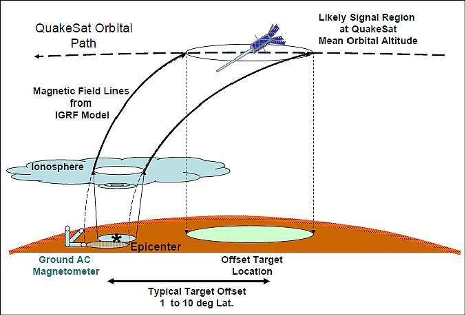
QuakeSat has a unique targeting problem, the path of the ELF signals is not direct line of sight like the radio signal. The exact path is not fully understood or modeled yet, but it is a function of ionosphere height and thickness, atmospheric turbulence, signal frequency, signal strength, receiver height. None of these variables are constant for any satellite pass over a target, and even vary during a specific pass.
In the pre-launch period, likely earthquake regions were laid out globally and given a related priority. The corner points and centroids of these regions were then propagated along our modeled path to the mean QuakeSat attitude. For point signal sources such as earthquake epicenters, a circular region was made surrounding this point. These points were then projected back down on to the Earth’s surface to create new offset targets.
QuakeSat accesses to these targets are then calculated using a simple vertical fence model to define collection On and Off times. Collection mode, sample rate and other data is then added to the collection load, which in turn is then uplinked to QuakeSat.
Since download time is a premium, most of the collections are over areas that we might expect a signal to originate from. Should QuakeSat survive its current eclipse period, we plan some additional negative area collections (i.e., area where we would expect no earthquakes or only noise signals).
Ground Segment
The SGS (Stanford Ground Station) was designed and built by a Stanford PhD Student, James Cutler. It has a 15 db gain Yagi antenna, mounted on a 3 m mast, on top of the fourth floor of the Durand Bldg on the Stanford University campus. It uses an ICOM preamp and ICOM 910H transceiver with 9600 baud packet capability. James Cutler has developed his own packet transmit/receive software that uploads and downloads packets in an AX.25 format. The data is received, buffered and transferred to the QuakeSat MCC (Mission Control Center) via FTP. The site has worked beautifully, and after minor software “tuning” the project is getting 400-500 k files from the satellite on each contact--on high elevation passes.
Ground monitor data: The overall data gathering strategy also included a ground component, namely a network of 35 three-axis magnetometer sensors, deployed every 30 km along major faults (e.g., San Andreas) in California. The frequency response of these ELF receivers is 0.1 to 4 Hz and they have an estimated detection radius of 15 km. Both the space and ground-based systems are designed to record time series data, with the objective of determining whether or not earthquake-related ELF signals exist, and if so, to characterize them in both time and frequency being careful to distinguish them from the many other magnetic signals present in space and near the ground (Ref. 9).

References
1) http://www.quakefinder.com/services/quakesat-ssite/
2) Matthew Long, Allen Lorenz, Greg Rodgers, Eric Tapio, Glenn Tran, Keoki Jackson and Robert Twiggs, Thomas Bleier, “A CubeSat Derived Design for a Unique Academic Research Mission in Earthquake Signature Detection,” AIAA/USU Conference on Small Satellites, Logan, UT, Aug. 12-15, 2002, SSC02-IX-6, URL: http://www.quakefinder.com/research/pdf/SSC_PAPER_SSC02-IX-6.pdf
3) Scott Flagg, Tom Bleier, Clarke Dunson, John Doering, Louis DeMartini, Paul Clarke, Lew Franklin, Jeannie Seelbach, Janine Flagg, Mark Klenk, Victor Safradin, James Cutler, Allen Lorenz, Eric Tapio,“Using Nanosats as a Proof of Concept for Space Science Missions: QuakeSat as an Operational Example,” 18 Annual AIAA/USU Conference on Small Satellites, Logan, Utah, Aug. 9-12, 2004, SSC04-IX-4, URL: http://38.112.59.48/research/pdf/QF_SmallSat2004.pdf
4) Tom Bleier, James Cutler, Eric Tapio, Allen Lorenz, Bob Twiggs, “QuakeSat: Low Cost University/Commercial Nanosatellite Collaboration,” CubeSat Developers Workshop, CalPoly, San Luis Obispo, CA, USA, April 8-10, 2004, URL: http://mstl.atl.calpoly.edu/~workshop/archive/2004/Spring/04b-Bleier-QuakeSat.pdf
5) Tom Bleier, Paul Clarke, James Cutler, Louis DeMartini, Clark Dunson, Scott Flagg, Allen Lorenz, Eric Tapio, “QuakeSat Lessons Learned: Notes from the Development of a Triple CubeSat,” URL: http://insa.netquire.com/docs/Lessons_Learned_Fina.pdf
6) Eric Tapio, “Reusable, Open Source, and Internet Enabled Software Tools for Efficient Small Satellite Design, Mission Planning, and Analysis,” URL: http://www.quakefinder.com/services/quakesat-ssite/documents/E_Tapio_siw4.pdf
7) Tom Bleier, Clark Dunson, “Simultaneous ELF Magnetic Field Monitoring of Earthquakes from a Nano-Satellite (QuakeSat) and a Ground Network,” 4th IWSE (International Workshop on Seismo Electromagnetics), Tokyo, Japan, March 15-17, 2005, URL: http://www.quakefinder.com/research/pdf/L3-3%20Bleier.pdf
8) http://www.quakefinder.com/services/quakesat-ssite/qs_january_20_full_report.htm
9) Thomas Bleier, Clark Dunson, “ELF Magnetic Field Monitoring of the San Simeon M6.4 quake from both QuakeSat and a Ground Network,” URL: http://www.quakefinder.com/research/pdf/QuakeFinderIWSE.pdf
10) http://www.quakefinder.com/services/quakesat-ssite/qs_september_12_full_report.htm
11) http://www.quakefinder.com/services/quakesat-ssite/qs_july_5_full_report.htm
The information compiled and edited in this article was provided by Herbert J. Kramer from his documentation of: ”Observation of the Earth and Its Environment: Survey of Missions and Sensors” (Springer Verlag) as well as many other sources after the publication of the 4th edition in 2002. - Comments and corrections to this article are always welcome for further updates (eoportal@symbios.space).