RAX (Radio Aurora eXplorer)
EO
Atmosphere
Mission complete
Gravity, Magnetic and Geodynamic measurements
Quick facts
Overview
| Mission type | EO |
| Agency | University of Michigan |
| Mission status | Mission complete |
| Launch date | 20 Nov 2010 |
| End of life date | 19 Jan 2011 |
| Measurement domain | Atmosphere |
| Measurement category | Gravity, Magnetic and Geodynamic measurements |
| CEOS EO Handbook | See RAX (Radio Aurora eXplorer) summary |
RAX (Radio Aurora eXplorer)
RAX is a collaborative nanosatellite science mission comprised of teams from the University of Michigan (UMich), Ann Arbor, MI (James W. Cutler), and SRI International, Menlo Park, CA (Hasan Bahcivan). The payload was developed at SRI, and the satellite bus was developed in the Michigan Exploration Laboratory (MXL). The mission is funded by NSF (National Science Foundation) to study space weather. The primary mission objective is to study plasma instabilities that lead to magnetic field-aligned irregularities (FAI) of electron density in the lower polar thermosphere (80-300 km). These irregularities are known to disrupt communication and navigation signals. The RAX project started in September 2008. 1) 2) 3) 4) 5)
The RAX mission will use a network of existing ground radars that will scatter signals off the FAI to be measured by a receiver on the RAX spacecraft (bistatic radar measurements).
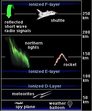
FAIs (Field-Aligned Irregularities) are dense plasma structures forming between the E and F layers of the ionosphere. Their sizes range from sub-meter to kilometer scales. FAIs are known to disrupt tracking and communications with spacecraft. The study of the physics of FAI formation will lead to forecasting models.
Spacecraft
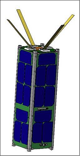
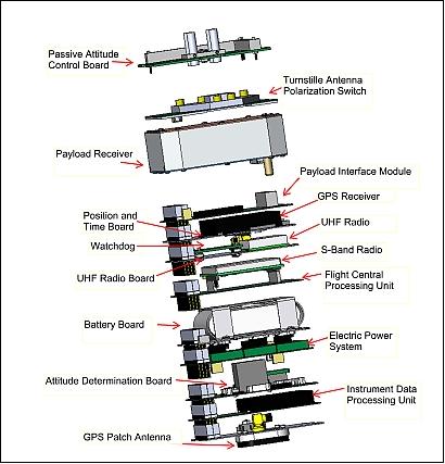
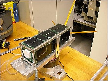
RAX is a 3U (3 unit) standard CubeSat with a volume of 10 cm x 10 cm x 30 cm and a mass of ~ 3kg. The nanosatellite structure uses a Pumpkin kit, which was modified by the project to suit the mission needs. Spacecraft stabilization is performed with passive magnetic control (aligned along one axis with the magnetic field lines).
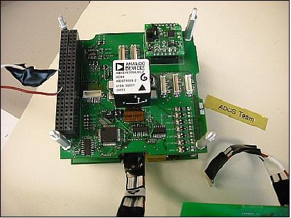
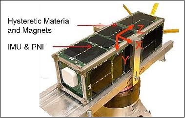
The ADCS (Attitude Determination and Control Subsystem) uses a passive magnetic system. Two magnetometers (MicroMag3 of PNI Corp.) 7), sun sensors and an IMU (Inertial Measurement Unit, ADIS16405 of Analog Devices Inc.) for attitude sensing and permanent magnets and hysteresis strips for attitude control. Coarse, single-axis sun sensors are integrated on each of the six faces of the RAX spacecraft to compliment magnetometer measurements. These sensors are photodiodes that measure the angle between the sun and the normal direction of the sensor. Three illuminated, non-parallel sensors are needed for a unique sun vector measurement. The sensors have a conical field of view with a half-angle of 70º. Since the sensors are mounted to the six orthogonal faces of the satellite, a complete sun vector measurement is not possible for all attitudes.
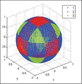
Legend to Figure 3: The axes are the directions of the satellite-fixed coordinate system. Each point on the sphere represents a possible direction to the sun in the satellite-fixed frame. The colors on the plot represent the number of illuminate sun sensors for the corresponding sun direction. Green means three sun sensors are illuminated, blue means two, and red indicates that one sun sensors is illuminated. This is a direct result of the fact that there is a sun sensor mounted on each of the six orthogonal faces of the satellite.
A GPS receiver (Novatel OEMV-1) provides orbital position and time. With knowledge of the position of the spacecraft (from GPS or two-line element information), the IGRF (International Geomagnetic Reference Field) database can be referenced and compared to the magnetometer to determine RAX’s attitude state.
To fully characterize and calibrate this magnetometer system within a working spacecraft, the UMich RAX team has constructed a large lab-based Helmholtz cage to generate both calibration and orbit-analog magnetic fields. The Helmholtz cage is capable of automatically simulating entire orbits in real-time through the use of Satellite Tool Kit and MATLAB, enabling the team to validate the spacecraft’s primary attitude sensor in the lab. 8) 9)
The EPS (Electrical Power Subsystem) employs triple-junction AsGa solar cells and Li-ion batteries. All solar panels are surface mounted. EPS consists of the following major elements:
- 4 separate solar panel regulators
- 22 V Emcore BTJM solar panels
- 6 V-8.4 V Li-ion battery
- Regulated 5 V, 3.3 V bus
- I2C telemetry
RF communications: TT&C communications are provided in UHF (UHF transceiver) at 38.4 kbit/s in downlink. The science data are transmitted in S-band (2.4 GHz) at 115.2 kbit/s. Use of UHF turnstile antenna and S-band patch antenna.
The Li-1 (Lithium-1) radio CubeSat Kit of Astronautical Development LLC, Sunnyvale, CA is used for UHF communications. 10)
Launch
RAX was launched as a secondary payload on Nov. 20, 2010 (UTC) on a Minotaur-IV expandable launch vehicle from Kodiak Island, Alaska. This multiple payload launch is supported by the DoD and is referred to as the STP-S26 (Space Test Program-26) mission. The primary payload on this mission is STPSat-2 (Space Test Program Satellite-2) of the USAF. 11) 12)
The following secondary payloads are part of the STP-S26 mission (all secondary payloads are documented in a separate file on the eoPortal):
• FalconSat-5 of USAFA (US Air Force Academy) at Colorado Springs, CO. FalconSat-5 has a mass of 161 kg.
• FASTSat-HSV (Fast, Affordable, Science and Technology Satellite-Huntsville), AL Corporation, developed by NASA/MSFC, VCSI (Von Braun Center for Science and Innovation), and Dynetics. FASTSat will be flying a total of six instruments, three of NASA and three of DoD. The mass of FASTSat is 180 kg.
• O/OREOS (Organism/ORganic Exposure to Orbital Stresses), a NASA/ARC nanosatellite mission of 5.2 kg mass (triple CubeSat).
• FASTRAC-1, -2, a nanosatellite pair of UTA (University of Texas, Austin) with a total mass of 54 kg.
• RAX (Radio Aurora Explorer), a triple CubeSat mission (3 kg) of NSF (National Science Foundation) - a CubeSat-based Ground-to-Space Bistatic Radar Experiment — Radio Aurora Explorer, developed by a team comprised of University of Michigan at Ann Arbor, MI and SRI International, Menlo Park, CA.
Orbit: Circular orbit, altitude = 650 km, inclination = 72º, with an orbital period of 97.7 minutes.
Mission Status
• Another 3U CubeSat, RAX-2, has been developed at UMich which was launched on October 28, 2011 as a secondary payload on NASA's NPP (NPOESS Preparatory Project) mission. The CubeSat launch was sponsored by NASA as part of the ElaNA-3 (Education Launch of Nanosatellite-3) program.
• In summary: The RAX-1 flight qualified the mission and the technology. NSF fostered an environment that enabled:
- Novel science mission exploration (successful functional demonstration of a novel, CubeSat-based bistatic radar experiment capable of exploring ionospheric disturbances)
- In-situ student training, both in science and engineering in all project phases (pre, during, post mission).
- Distributed collaboration of science and engineering teams.
• RAX-1 mission stopped operations in the spring of 2011 (the mission ended prematurely after more than 60 days of operation due to a power system anomaly): Unfortunately, an anomaly on the solar panels resulted in a degradation of power generation until, after several months, RAX-1 was unable to generate power anymore. This anomaly ultimately resulted in the premature end of the mission. Despite this early end, the RAX-1 mission still made great strides in CubeSat design, and was able to execute bistatic radar measurements that had never before been performed with a CubeSat. All other subsystems also performed well (Ref. 17).
Note: During the RAX-2 development, it was discovered that the RAX-1 EPS creates electro-magnetic interference at the same frequency as the UHF communication, and this was likely the cause of the day time problems when the solar panels were illuminated. This noise has been mitigated through a design change to the EPS for the RAX-2 satellite. The S-Band Microhard MHX-2400 was not operated during the RAX-1 mission given the power anomaly and complexity in operating a dish to support the radio. 13)
Some performance characteristics and/or events observed during the RAX mission (a post mission analysis): 14)
- RAX experiment: The receiver had excellent recovery from direct radar transmissions.
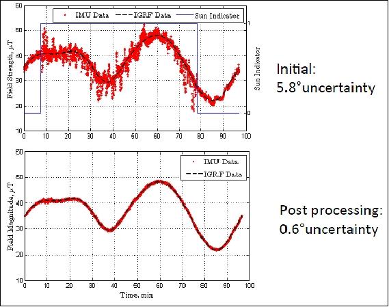
- Bus systems: The magnetometer calibration and noise removal was successful. As a consequence, the magnetic measurement uncertainty was reduced by an order of magnitude in post processing. 15)
The RAX-1 magnetometer suite consisted of two internally mounted tri-axial magnetometers and four dual axis magnetometers mounted on external faces of the satellite. The internal magnetometers were calibrated using a novel, scalar based method that involved simple rotations of the satellite in a known magnetic field during ground calibration. Once on orbit, calibration was applied but the data was susceptible to satellite-induced noise (Ref. 17).
A novel on-orbit calibration method was developed that used the IGRF magnetic field model and current satellite measurements. The majority of the on-orbit noise was coming from electric current loops in the satellite, and noise was significantly reduced to just above the noise floor of the sensor itself. The results are plotted in Figure 8. External magnetometer data has not been processed due to its inherent lower resolution and higher noise floors.
- Bus systems: The GPS receiver operated as predicted and maintained lock in the experimental zones.
- Bus systems: The UHF Lithium-1 radio performed extremely well; however, the project experienced some interference issues.
Expected max power at RAX from the ground station: - 80 dBm
Measured signal level at RAX: - 70 dBm

- Bus systems EPS: The regulation and the power subsystem worked well; however, the panels systematically degraded throughout the mission resulting in an eventual loss of power (Ref. 17).
Degradation of the +Y panel is shown in Figure 10. Power versus sun sensor measurements are plotted where color indicates temperature of the panel. Two sets of data are plotted over the course of 12 days. The plots show that as the mission progressed, the panels produced less power for given sun sensor readings. There was a larger than expected temperature dependence as well; the panel power dropped off to temperatures 40º-50ºC lower than calculated.
After extensive ground testing, it was concluded that the panels experienced gradual degradation on orbit due to cell shorting caused by individual cells on each panel being partially shadowed by the UHF antennas. Because bypass diodes were not connected, the cells experienced a strong reverse voltage bias that destroyed them.
RAX-1 maintained a positive power budget for the first portion of the mission. Power degradation was discovered in late December 2010. Nominal operations were modified to place RAX-1 into an ultra low power operations mode that enabled the batteries to charge at lower power generation levels. Ultimately, the panel degradation was sufficient to halt power production and RAX-1 ceased operation.
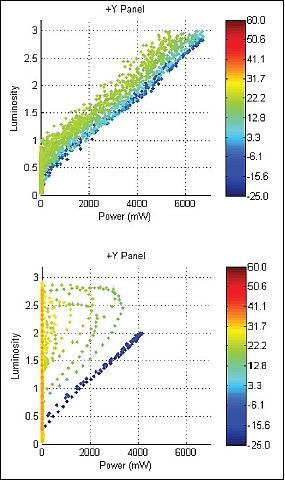
Legend to Figure 10: The color of the points corresponds to degrees in C. For b) temperature drastically reduces power output.
- RF communications: The UHF radio system, the AstroDev Li-1, operated nominally. The radio was run at 9.6 kbit/s with an output power of 0.5 W. Operationally, there was difficulty in communicating with RAX-1 during day passes in Ann Arbor, Michigan. This was attributed to local noise sources. Night passes were reliable. The input filter on the Li-1 was wider than expected and thus no Doppler correction was needed on the uplink frequency. RSSI was monitored during the mission and peak values were greater than -80 dBm during non-experimental times (Ref. 17).
The S-Band Microhard MHX-2400 was not operated on RAX during light. Given the power anomaly and the complexity in operating a dish to support the Microhard, only UHF communication was used.
- Lessons learned:
1) Beacons are simple, but a well thought out beacon strategy is an important mission capability
2) From experience, power subsystems are still an “Achilles heal” of small satellites
3) Test. Keep testing until there is is no more time left. The RAX failures occurred in environments where the project did not or could not test anymore.
• About three weeks after launch (Dec. 10, 2010), the researchers conducted their first radar experiment using the Poker Flat Incoherent Scatter Radar (PFISR), which is operated by SRI International under a cooperative agreement with NSF. 16)
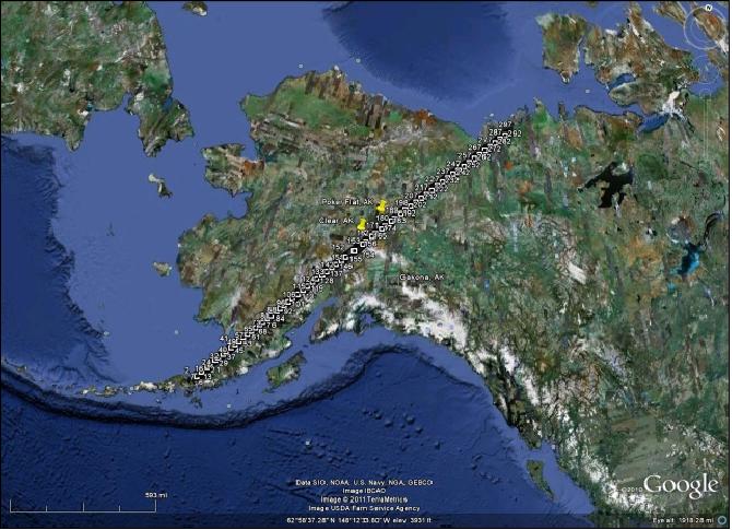
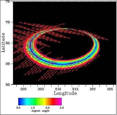
A 300 second active radar experiment was conducted with PFISR on 10 December 2010. Figure 11 is a plot of the satellite location over time where the blue cross is the radar location on the ground and the red cross is the bore sight location of the radar transmissions at 650 km. Figure 12 shows the spacecraft track projected on a map of North America (Ref. 17).
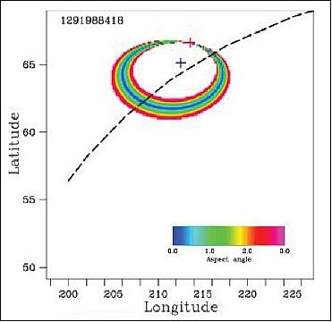
Legend to Figure 11: The dashed line is the satellite track. The pass was ascending and the satellite moved from bottom left to top right. The blue cross hairs correspond to the PFISR location. The red cross hairs correspond to the direction of transmission. The colored rings are the aspect ratio, an element of the science analysis.
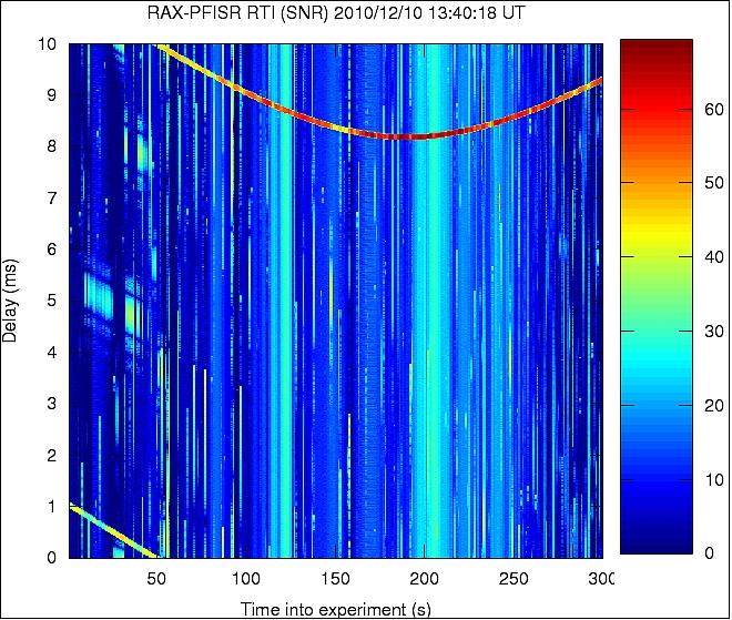
RAX experiment: There was excessive interference during the RAX experiment over Alaska. Figure 13 is a range-time-intensity for this experiment. The data is as expected. The direct (PFISR-to-RAX) radar pulses (emanating from radar side lobes) are seen as the intense red line from 50–300 s with range delays of 8–10 s. The range delay decreases as RAX approaches the radar. The strong signal in the lower left is due to aliasing in the range delay calculations. Disturbances between 0-50 s with delays of approximately 5 and 8 ms are due to interference from additional, nearby radar systems. In this experiment, no FAI were detected nor were they expected. Electron density and magnetometer readings indicated very quiet geophysical conditions (Ref. 17).
In addition, the receiver recovered from saturation extremely well. Side lobe transmissions from the radar saturate the receiver. It recovers within 100 microseconds thus allowing for low noise measurements of any radar echoes. This feature demonstrates the extremely sensitive and precise sensing capability of the RAX-1 receiver.
• Results from on orbit noise floor measurements of the payload receiver were better than any ground based testing prior to launch. On December 8, 2010, the payload receiver of RAX-1 measured a spectrum over the Indian Ocean (Figure 14). So far, attitude of the satellite during this experiment has not yet been calculated. The calculated noise power within the ±50 kHz band centered at 0 Hz is -113 dBm. The calculated noise (-113 dBm) was better than the best achieved in the lab and anechoic chamber (-110 dBm). This indicated the receiver and satellite systems were operating extremely well. 17) 18)
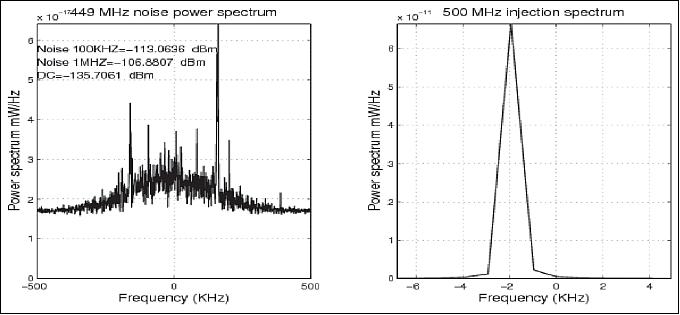
Legend to Figure 14: Initial receiver assessments are plotted. On the left, the noise floor of the receiver was measured during a pass over the Indian Ocean. Noise levels in orbit were lower than those achieved on the ground. On the right, a test tone was injected into the receiver at 500 MHz onboard RAX. It matched ground testing. The receiver was fully functional on orbit.
• The RAX project team established contact with the spacecraft and tested various subsystems like power, GPS, etc. An student operations team tracked RAX-1 during its four to six passes daily. Uplinks were most successful during night passes. A survey of local noise spectrum indicated strong local noise near RAX-1 UHF frequencies during the day.
• After launch, the first signal acquisition of RAX-1 was made by amateur radio operators in Hawaii - receiving automated RAX telemetry beacons.
RAX Experiment
To characterize the FAI (Field-Aligned Irregularity) anomalies, a ground-based radar transmitter will be used in conjunction with a spaceborne radar receiver onboard the RAX spacecraft to measure the FAI intensity and distribution. The ground-based ISR (Incoherent Scatter Radar) at Poker Flat, AK, also referred to as PFISR (Poker Flat Incoherent Scatter Radar), will emit high-power radio frequency (RF) pulses into the ionosphere to be scattered off the FAI structures. Alternative ground radars are also being examined to achieve a greater number of experiments. 19)
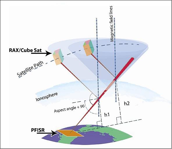
Legend to Figure 15: RAX is shown orbiting above the ground radar station as it scatters radio waves off the FAI plasma structures.
The PFISR is used to direct an electromagnetic beam towards the ionosphere. The ionospheric irregularities which lie on the path of this beam scatter the incident electromagnetic energy in the shape of hollow cones. As the RAX nanosatellite moves in its orbit, it passes through the conical scattering regions and takes measurements. The measurements are tagged with altitudes (h1, h2, etc.) and aspect angles of the scattering targets. The aspect angle (θ) provides alignment information - it is a measure of how well the irregularities are aligned with the geomagnetic field lines.
The RAX nanosatellite is used to receive the scattered radiation, referred to as “radio aurora”, from the ionosphere and perform on board radar signal processing. The principle RAX payload is a radar receiver which will measure the amplitude and phase of the radio aurora along the satellite track. The signals will be sampled at 1 MHz and stored into a 1.20 GByte radar buffer memory where they will be post-processed by the payload processor.
Scattering geometry: The incident electromagnetic beam generated by the PFISR, which is pointed at certain elevation (ε) and rotates about certain azimuth (α), is narrow with a beam width around 3º and has a spherical beam front. The irregularities falling within the path of the incident beam scatter the signal in the form of a hollow cone shape. The RAX passes through each cone and takes readings.
RAX payload: The RAX payload receiver, developed at SRI, operates in a snapshot acquisition mode collecting raw samples at 1 MHz for 300 s over the experimental zone. Following each experiment, the raw data is post-processed for range-time-intensity and Doppler spectrum. The snapshot raw data acquisition enables flexibility in forming different radar pulse shapes and patterns. In addition, the PFISR electronic beam steering capability can be utilized for simultaneous multiple beam position experiments. 20)
The radar receiver is capable of operation with the five UHF ISRs (Incoherent Scatter Radars):
- PFISR (Poker Flat Incoherent Scatter Radar), Poker Flat, AK
- RISR (Resolute Bay Incoherent Scatter Radar), Alberta, Canada
- ESR (EISCAT Svalbard Radar, in Longyearbyen, Spitzbergen, Norway)
- Millstone Hill ISR of MIT in Westford, MA, USA, and
- Arecibo ISR in Puerto Rico.
The receiver can also operate with the MUIR radar located at the HAARP (High Frequency Active Auroral Research Program) facility in Gakona, AK, as part of active experiments. The satellite can perform 2-3 experiments per day. Figure 17 shows the 1-minute satellite tracks that pass through the scattering zone. There are ~1000 passes good for experiments in the 1-year mission lifetime.

New experimental geometry enabled by RAX
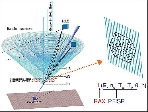
The RAX mission is specifically designed to remotely measure, with high angular resolution (~0.5º), the 3D k-spectrum (spatial Fourier transform) of ~1 m scale FAI as a function of altitude, in particular measuring the magnetic field alignment of the irregularities. The spacecraft will measure ``radio aurora'', the Bragg scattering from FAI that are illuminated with a narrow beam incoherent scatter radar (ISR) on the ground. The scattering locations are determined using a GPS-based synchronization between ISR transmissions and satellite receptions and the assumption that the scattering occurs only inside the narrow ISR beam. Figure 18 shows a drawing of the irregularities (red wiggles), the magnetic field lines, the radar beam, radio aurora (cones) and the satellite (cubes), and the satellite tracks. The irregularities inside the narrow radar beam and at a given altitude scatter the signals in a hollow cone shape. The thickness of the wall of each cone is a measure of magnetic aspect sensitivity, which is also a measure of plasma wave energy distribution in the parallel and perpendicular directions with respect to the geomagnetic field.
The main RAX science data product is I(E, Ne, Te, Ti, h, θ), that is, irregularity intensity (I) as a function of convection electric field (E), electron density (Ne), electron and ion temperatures (Te, Ti), altitude (h), and magnetic aspect angle (θ). RAX measures I, the ISR measures the plasma parameters, and (h, θ) are given by the experimental geometry. The list of potential plasma waves making up the meter-scale irregularities in the ionospheric E and F regions include Farley-Buneman, electrostatic ion cyclotron, Post-Rosenbluth, lower hybrid, and upper hybrid waves. Radar returns will be analyzed to identify the waves responsible for radar scatter and to determine the ionospheric conditions leading to the corresponding plasma instabilities.
PFISR (Poker Flat Incoherent Scatter Radar)
PFISR is a facility of the PFRR (Poker Flat Research Range) located in Poker Flat, Alaska (located about 50 km north of Fairbanks at 65.07º N, 147.28º W) and is used by scientists to study the upper atmosphere and the ionosphere. This radar was built in a joint collaboration between the NSF (National Science Foundation) and SRI and is now operated by SRI International. The radar is built using a phased-array antenna system which can be remotely controlled by scientists and the radar beam can be electronically steered instantaneously to sense multiple regions of the ionosphere.
The radar consists of 128 panels. Each panel consists of 32 antenna element units placed in an 8 x 4 rectangular array. The whole radar has a size of 30 m x 30 m consisting of 4,096 antennas as shown in Figure 19. The antennas are of the crossed dipole type with two dipoles placed at 90º to each other and excited with currents which are 90º out of phase (circular polarization) and can be operated at a frequency of 449 MHz (UHF). Since scientists can select which antenna to turn on and which to turn off, the radar is capable of generating different antenna patterns. PFISR is placed so that it faces near the direction of the magnetic north.
PFISR has a combined transmission power of ~2 MW. By changing the phase of the current in the different antenna elements the radar beam can be electronically steered. This unique feature of PFSIR is especially important for studying rapidly moving features of the atmosphere.
The PFISR facility is part of the AMISR (Advanced Modular Incoherent Scatter Radar) system. PFISR is actually the first of the AMISR facilities built and operated remotely by SRI International.. 21) 22) 23) 24) 25)

References
1) “SRI International and the University of Michigan Awarded National Science Foundation Contract to Build CubeSats for Space Science,” Oct. 1, 2008, URL: http://www.sri.com/news/releases/100108.html
2) “Researchers And Students To Develop Small Cubesat Satellites,” Space Daily, Oct. 2, 2008, URL: http://www.spacedaily.com/.../Researchers_And_Students_To_Develop_Small_Cubesat_Satellites
3) Catherine Walker , Darren McKague, James Cutler, “The Nanosatellite Pipeline: Future in Space-Based Research,” Proceedings of the 2010 IEEE Aerospace Conference, Big Sky, MT, USA, March 6-13, 2010
4) Therese Moretto Jorgensen, “The NSF Cubesat program : A brief update,” Proceedings of the 2009 CubeSat Developers' Workshop, San Luis Obispo, CA, USA, April 22-25, 2009
5) James Cutler, Sara Spangelo, Matt Bennett, Andy Klesh, Hasan Bahcivan, “RAX Communication Reflections,” URL: https://web.archive.org/web/20140712145950/http://mstl.atl.calpoly.edu:80/~bklofas/NSF_comm/20091216_parc55/3_Cutler_RAX.pdf
6) http://www.windows.ucar.edu/spaceweather/images/atmos_layers_new_gif_image.html
7) “MicroMag3 3-Axis Magnetic Sensor Module,” URL: http://www.sparkfun.com/datasheets/Sensors/MicroMag3%20Data%20Sheet.pdf
8) Andrew Klesh, Sheryl Seagraves, Matt Bennett, Dylan Boone, James Cutler, Hasan Bahcivan, “Dynamically driven Helmholtz Cage for experimental magnetic attitude determination,” 2009 AAS/AIAA Astrodynamics Specialist Conference, Pittsburgh, PA, USA, Aug. 9-13, 2009, AAS-09-311
9) Kiril Dontchev, Andy Klesh, Matthew Bennett, James Cutler, “In-Lab Testing for Attitude Determination and Control,” CubeSat Workshop, Utah State University, Logan, UT, Aug 9t, 2009
10) http://www.astrodev.com/public_html2/downloads/datasheet/LithiumUserManual.pdf
11) http://aoss.engin.umich.edu/articles/view/150
12) http://www.orbiter-forum.com/showthread.php?p=219924
13) John C. Springmann, JamesW. Cutler, Hasan Bahcivan, “Initial Flight Results of the Radio Aurora Explorer,” Proceedings of IAC 2011 (62nd International Astronautical Congress), Cape Town, South Africa, Oct. 3-7, 2011, IAC-11.B4.4.5, URL: http://rax.engin.umich.edu/wp-content/uploads/files/IAC_2011_JSpringmann.pdf
14) James Cutler, Hasan Bahcivan, Mathew Bennett, John Buonocore, Rick Doe, and the RAX Team, “RAX – Initial Flight Summary,” 8th Annual CubeSat Developers’ Workshop, CalPoly, San Luis Obispo, CA, USA, April 20-22, 2011, URL: http://rax.engin.umich.edu/wp-content/uploads/files/Cutler-CSW-2011.pdf
15) Odile Clavier, Theodore Beach, Brynmor Davis, Ariane Chepko, James Cutler, “Enabling low-cost, high accuracy magnetic field measurements on Small Sats for space weather missions,” Proceedings of the 25th Annual AIAA/USU Conference on Small Satellites, Logan, UT, USA, Aug. 8-11, 2011, paper: SSC11-I-5
16) Ellen Ferrante, “Tracking the Causes of Space-Based Weather Disruptions,” NSF, March 16, 2011, URL: http://www.nsf.gov/discoveries/disc_summ.jsp?cntn_id=118950
17) James W. Cutler, Hasan Bahcivan, John C. Springmann, Sara Spangelo, “Initial Flight Assessment of the Radio Aurora Explorer,” Proceedings of the 25th Annual AIAA/USU Conference on Small Satellites, Logan, UT, USA, Aug. 8-11, 2011, paper: SSC11-VI-6
18) http://rax.sri.com/index.html
19) Prawal Shrestha, Ashish Maharjan, Hunain Kapadia, “Radio Aurora Explorer, Nanosatellite Radar: Data Inversion,” April 28, 2009, URL: http://www.wpi.edu/Pubs/E-project/Available/E-project-042809-212803/unrestricted/Final_Report_RAX_Mission.pdf
20) Hasan Bahcivan, James Cutler, “Radio Aurora Explorer: Investigating ionospheric turbulence response to magnetospheric forcing,” 91st AMS (American Meteorological Society) Annual Meeting, Seattle, WA, January 23-27, 2011, URL: http://ams.confex.com/ams/91Annual/webprogram/Paper179924.html
21) Anja Strømme, John Kelly, Craig Heinselman, "Future plans and direction for AMISR (Advanced Modular Incoherent Scatter Radar) systems around the globe," Proceedings of the ITM (Ionosphere-Thermosphere-Mesosphere) Conference, Redondo Beach, CA, Feb 10-12, 2009
22) J. D. Kelly, C. J. Heinselman, “Initial results from Poker Flat Incoherent Scatter Radar (PFISR),” Journal of Atmospheric and Solar-Terrestrial Physics, Volume 71, Issues 6-7, May 2009, p. 635
23) Bob Robinson, “The Advanced Modular Incoherent Scatter Radar (AMISR), Historical Perspectives,” URL: http://www.noao.edu/nsf/presentations/FACILITIES/THF09a%20ROBINSON%20LFW%20AMISR%20talk.pdf
24) “National Science Foundation Awards a Grant to SRI International for Upper Atmospheric Research Radar Facility ,” Aug. 26, 2003, URL: http://www.sri.com/news/releases/08-26-03.html
25) http://isr.sri.com/iono/amisr/
The information compiled and edited in this article was provided by Herbert J. Kramer from his documentation of: ”Observation of the Earth and Its Environment: Survey of Missions and Sensors” (Springer Verlag) as well as many other sources after the publication of the 4th edition in 2002. - Comments and corrections to this article are always welcome for further updates (eoportal@symbios.space).