RISAT-2 (Radar Imaging Satellite-2)
EO
Atmosphere
Mission complete
Land
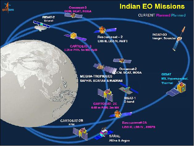
Launched in April 2009, Radar Imaging Satellite-2 (RISAT-2) is an X-band SAR (Synthetic Aperture Radar) reconnaissance satellite of the Indian Space Research Organization (ISRO). As India’s first satellite with a SAR instrument, data acquired from RISAT-2 significantly enhanced ISRO’s capability for Earth observation, particularly for the management of disasters, and environmental and urban mapping.
Quick facts
Overview
| Mission type | EO |
| Agency | ISRO |
| Mission status | Mission complete |
| Launch date | 20 Apr 2009 |
| End of life date | 30 Oct 2022 |
| Measurement domain | Atmosphere, Land, Snow & Ice |
| Measurement category | Vegetation, Soil moisture, Snow cover, edge and depth, Atmospheric Winds |
| Measurement detailed | Vegetation Cover, Snow cover, Soil moisture at the surface, Oil spill cover, Vegetation Canopy (height) |
| Instruments | SAR-X |
| Instrument type | Imaging microwave radars |
| CEOS EO Handbook | See RISAT-2 (Radar Imaging Satellite-2) summary |

Summary
Mission Capabilities
RISAT-2 features an X-band SAR instrument (XSAR) that employs electronic beam steering to be operated in various observation modes, including various polarisation combinations.
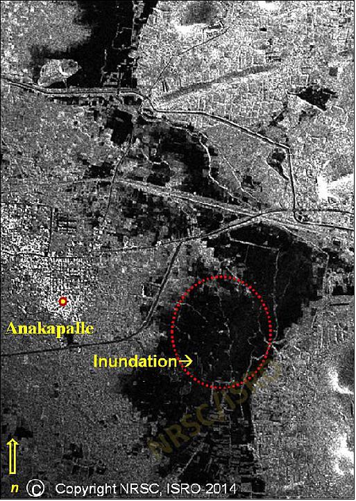
Possessing 24-hour, all-weather monitoring capability, XSAR data is used for applications including flood mapping, oil slick detection, landslide mapping, agriculture, forestry and urban mapping over India and neighbouring regions. XSAR is also used specifically for the effective management of natural disasters including the assessment of cyclone HudHud in October 2014.
Performance Specifications
RISAT-2 features four operational modes: Stripmap mode, Wide coverage ScanSAR, Spotlight mode and Mosaic mode. Stripmap mode utilises SAR targeted on wide geographical swaths at a resolution of 3 m. ScanSAR mode employs three beams in the nominal wide coverage mode to allow for a swath width of up to 100 km.
However, this reduced the ground resolution to between 8 m and 20 m. In Spotlight mode, a specific, pre-assigned target is focused on at a resolution of less than 1 m. To enable the extension of the limited coverage of spot mode, mosaic mode focuses on a number of spots in the same general target area with a slightly lower resolution of 1.8 m.
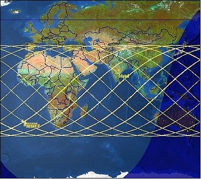
RISAT-2 undergoes a near-circular mid-inclination orbit at an altitude of 548 km and an inclination of 41°. It features a LTAN (Local Time of Ascending Node) of 0600 hours with a period of approximately 90 minutes.
Space and Hardware Components
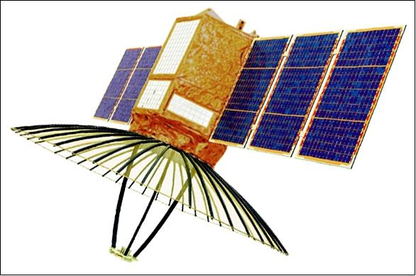
Built by Israel Aerospace Industries Ltd. (IAI) with an original design life of five years, RISAT-2 is based on the TecSAR minisatellite OptSat-2000 platform of IAI. Featuring a low-mass design of 300 kg, the spacecraft is three-axis stabilised with a highly agile bus design and a body-pointing parabolic dish antenna system which together enabled increased viewing capabilities. Electrical power is provided by two onboard solar panels and the AOCS (Attitude and Orbit Control Subsystem) enables a high degree of pointing accuracy. The payload data is downlinked in X-band at a data rate of 620 Mbit/s.
RISAT-2 (Radar Imaging Satellite-2)
Overview Spacecraft Launch Mission Status Sensor Complement References
RISAT-2 was an X-band SAR (Synthetic Aperture Radar) reconnaissance satellite of ISRO (Indian Space Research Organization), Bangalore, India. The spacecraft was built for ISRO by IAI/MBT (Israel Aerospace Industries Ltd.) based on the TecSAR minisatellite design of IAI (launch Jan. 21, 2008, provided by ISRO) of the Israeli MoD (Ministry of Defense).
RISAT-2 was built as part of an acceleration of Indian reconnaissance satellite procurement after the 2008 Mumbai (Bombay) terror attacks, and due to delays with the indigenously developed RISAT-1 spacecraft, which was due for launch in 2011. Hence, RISAT-2 was India's first satellite with a synthetic aperture radar (SAR), which possessed a 24-hour, all-weather monitoring capability. 1)
Spacecraft
RISAT-2 was a minisatellite featuring a low-mass design (S/C mass of 300 kg, including a payload mass of 100 kg). The spacecraft was 3-axis stabilized, using the OptSat-2000 platform (of TecSAR bus heritage). The design kept the bus and payload well separated so that changes due to growth potential in either one element could have a minimum effect on the other element.
Electrical power of 750 W (EOL) was provided by two solar panels. The AOCS (Attitude and Orbit Control Subsystem) provided a high degree of pointing accuracy. An onboard data storage capacity of 240 Gbit was provided. The spacecraft design life was 5 years (minimum).
The highly agile bus design, in combination with the body-pointing parabolic dish antenna system, permitted increased viewing capabilities from the spacecraft. The spacecraft/antenna system could have been dynamically redirected to any direction of the flight path (i.e., in the cross-track as well as in the along-track direction). Thus, a wide FOR (Field of Regard) within the incidence angle range could have been obtained on either side of the ground track for event monitoring coverage.
Launch
The RISAT-2 spacecraft was launched on April 20, 2009 (01:15:00, UTC) on a PSLV launcher (PSLV-CA C12) from ISRO's SDSC (Satish Dhawan Space Center) at SHAR (Sriharikota) on the east coast of India. 2) 3)
- The secondary payload on this flight was ANUSat, a microsatellite of Chennai-based Anna University, India with a mass of ~ 40 kg.
Orbit
Near-circular mid-inclination orbit, altitude = 548 km, inclination = 41o, period of ~90 minutes (the orbit is nearly identical to that of the TecSAR spacecraft).
RF communications
The payload data were downlinked in the X-band at a data rate of 620 Mbit/s.
The ISRO/NRSC (National Remote Sensing Center) was the focal point for the distribution of remote sensing satellite data products in India and its neighbouring countries. NRSC had an Earth station at Shadnagar, about 55 km from Hyderabad, to receive data from almost all contemporary remote sensing satellites. NDC (NRSC Data Center) was a one-stop-shop for a range of data products with a wide choice of resolutions, processing levels, product media, out scales, area coverage, revisit, season and spectral bands. Data products were supplied in a wide variety of media and formats.
Mission Status
• October 30, 2022: After 13 years of operation, RISAT-2 made an uncontrolled reentry into Earth’s atmosphere at the predicted impact point in the Indian Ocean near Jakarta, on 30th October 2022 at 00:06 UTC.
On re-entry, there was no fuel left in the satellite and hence there were no contaminations or explosions expected.
Studies confirmed that the pieces generated due to aero-thermal fragmentation would not have survived reentry heating and hence no fragments would have impacted on Earth.
Indian System had been monitoring the re-entry for the last month with analysis carried out by Vikram Sarabhai Space Centre and ISRO Telemetry, Tracking and Command Network teams, through its in-house developed analysis software, utilizing Multi Object Tracking Radar (MOTR) at Satish Dhawan Space Centre, Sriharikota.
MOTR tracked RISAT-2 regularly and the data were used for further analysis and orbit determination. 14)
• February 2015: The RISAT-2 spacecraft and its payload are operating nominally in 2015. 4)
• October 14, 2014: Andhra Pradesh government plans to use satellite imagery provided by Indian Space Research Organization (ISRO) and National Remote Sensing Center (NRSC) for assessing the destruction caused by cyclone Hudhud. HudHud was a severe cyclonic storm which hit Andra Pradesh recently. 5)
• The RISAT-2 spacecraft and its payload are operating nominally in 2014. 6) 7)
• The RISAT-2 spacecraft and its payload are operating nominally in 2012.
• In 2011, the RISAT-2 spacecraft and its payload are operating nominally.
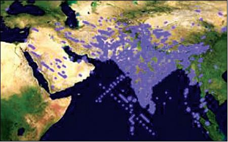
• NRSC has acquired XSAR data in various observation modes (Figure 6).
The data was used for such applications as
- flood mapping,
- oil slick detection,
- landslide mapping,
- agriculture,
- forestry and urban mapping.
• First-day imaging by RISAT-2 was done on April 29, 2009 (Ref. 9).
Sensor Complement
XSAR (X-band SAR Instrument)
XSAR (of XSAR heritage flown on TecSAR) was designed and developed by Elta Systems Ltd. of Ashdod, Israel, a subsidiary of IAI.
XSAR operated at a centre frequency of 9.59 GHz (3.1 cm wavelength) with a revisit period of 3 or 4 days and a repeat cycle of 14 days, the look angle varied from 20-45o and the instrument was capable of acquiring data from both left and right look directions of the subsatellite track. The RISAT-2 data enhanced ISRO's capability for earth observation, especially for the management of disasters like floods, cyclones, landslides, etc. in a more effective way. 8) 9)
XSAR used a large dish-like antenna to transmit and receive radar signals that penetrated thick clouds providing images up to 1m resolution. The multi-mode XSAR was capable of high-resolution imaging of Spotlight (1 m), Stripmap (3 m), Mosaic (1.8 m) and Wide coverage (8 m) modes on swaths of 10 to 120 km.
The highly agile bus design in combination with the body-pointing parabolic antenna dish system permitted greatly increased viewing capabilities of the spacecraft. The spacecraft/antenna system were dynamically redirected in any direction of the flight path (i.e. in the cross-track as well as in the along-track direction). Thus, a wide FOR (Field of Regard) within the incidence-angle range were obtained on either side of the ground track for event monitoring coverage.
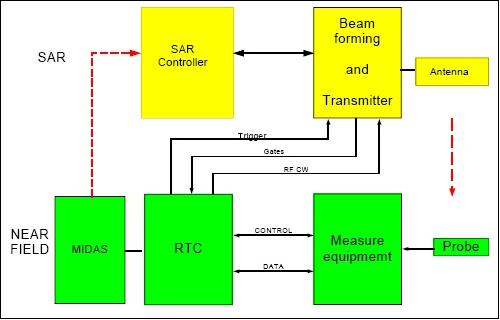
The XSAR instrument consists of five major subsystems 10) 11)
- RSC (Radar Signaling and Control) system
- MTT (Multi-Tube Transmitter)
- Deployable paraboloid mesh antenna with electronic beam steering
- OBR (Onboard Recorder) of 256 Gbit capacity
- DLTU (Data-Link Transmission Unit).
The payload modules were separated from the bus so that only cables and wires connected the two. The payload modules occupied a section close to the antenna (Figures 7 and 10). The OBR and DLTU components were part of the bus modules.
The MTT was composed of 10 RF TWT amplifiers referred to as CTWTA (Channeled Traveling Wave Tube Amplifier). Only 8 CTWTAs (out of 10) were used during an imaging phase; the other two were kept as cold redundancy. The MTT arrangement supported graceful degradation even if only seven of the ten CTWTAs remained in working order. The reflected signal passes through the feeder to a Front End (FE) that contained a circulator and LNA (Low Noise Amplifier).
A fast electronic switch at the receiver input selected the power that came from one out of the eight FEs. This power was amplified and sampled by a fast A/D (Analog/Digital) converter. The sampled data passed through a 6 to 3-bit per sample BFPQ (Block Floating Point Quantization) compression algorithm. The source data was then recorded onto the OBR (Onboard Recorder).
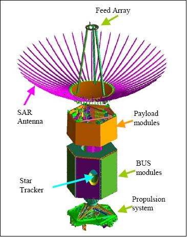
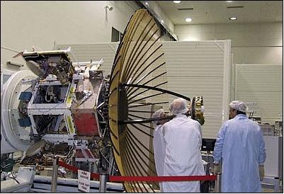
The radiating element of XSAR was the parabolic antenna, a deployable umbrella reflector, with a rigid CFRP (Carbon Fiber Reinforced Plastic) central dish and a set of knitted mesh gores stretched by skeleton ribs. The ribs lay on the surface of a parent paraboloid where each gore surface had a paraboloid cylinder contour. The configuration of the antenna is shown in Figure 7.
A high paraboloid reflector surface accuracy was achieved by ribs position adjustment after mesh gores mounting. The antenna measurement technique was verified using the method of stereo photogrammetry. The entire reflector mesh had a mass of < 0.5 kg.
In the XSAR system design, a derivative of the BFPQ algorithm was used, namely MBFPQ (Modified Block Floating Point Quantization). The MBFPQ algorithm exploited the fast CPU computing power of the payload (80486DX2 CPU) thus avoiding the need to assume a Gaussian distribution of the data. 12)
All electronics and RF devices (MTT and RSC) of the XSAR payload were part of the hexagonal container as shown in Figure 10.
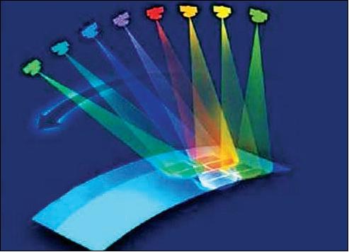
The electronic beam steering capability was achieved by using an antenna feed array in the focal plane (the power generated in the MTT was directed toward different feeders in the antenna feed array). Each feeder had a different position relative to the antenna focal point: hence, a multi-beam pattern was created (Figure 8). The antenna included a TTD (True Time Delay) function for the electronic steering with a very wideband beam. As a consequence of the wideband antenna and the TTD feature, the system's range resolution was not limited as in the case of an active phased array antenna.
All electronic circuits and RF modules of the payload were installed into a hexagonal container, including the MTT and the RSC (Figure 10). The OBR and DLTU were mounted in the bus section of the spacecraft.
Modes of operation
The multi-mode payload employed electronic beam steering, which could have been operated in various observation modes including various polarization combinations (optional): HH, HV, VH, VV. 13)
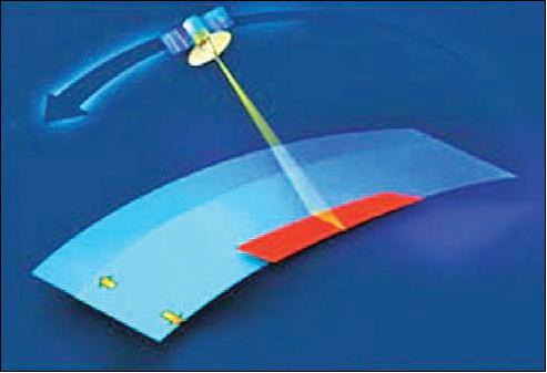
• Stripmap mode
The synthetic apertures were targeted on wide geographical swaths. The spacecraft performed synchronous imaging and did not change its orientation during observations, except for some small manoeuvres due to the need to keep the imaging strip parallel to the ground track. Squinted strip imaging was possible.
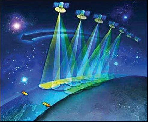
• Wide coverage ScanSAR
The coverage of large strips was achieved by electronic beam steering. Three beams were used in the nominal wide coverage mode which created three footprints (subswaths) in the target area. The ground resolution in this mode was decreasing since the integration time was split up among the subswaths.
The swath width could have been increased by using more antenna beams. In principle, the swath width could get to more than 100 km for some incidence angles. However, this reduced the ground resolution to about 20 m.
• Spotlight mode
this focused on a specific, pre-assigned target. In spotlight, the spacecraft performed mechanical steering to halt the antenna footprint in a specific target area. The longer integration time over the spot target area yields an improved azimuth resolution. The range resolution was achieved in adjusting the bandwidth to the incidence angle. The TecSAR ability for spotlight imaging in squint allowed for multi-look imaging without any loss in resolution. To obtain a multi-look image of a given target area, a number of spotlight images were observed, each at a different squint angle.

• Mosaic mode
the radar imager slews its focus on a number of spots in the same general target area. The mosaic mode enabled extending the limited coverage of the spot mode by using the electronic steering capability of XSAR. In mosaic mode, the radar beam scanned in the range direction while the mechanical manoeuvring advanced the strip line in the azimuth direction. Hence, this mode could also have be interpreted as the spot version of ScanSAR.
Operation mode | Resolution |
Wide coverage ScanSAR mode | 8 m |
Stripmap mode | 3 m |
Super stripmap (mosaic) mode | 1.8 m |
Spotlight mode | < 1 m |
References
1) "India readies Israeli radar spysat to eye Pakistan," Spaceflight Now, April 18, 2009, URL: http://spaceflightnow.com/news/n0904/17milsat/
2) "Indian rocket launches Israeli-built spy satellite," Spaceflight Now, April 20, 2009, URL: http://spaceflightnow.com/news/n0904/20pslv/
3) http://www.isro.gov.in/Spacecraft/risat-2
4) Vinay K Dadhwal, "Indian Space Program - update on activities," 52nd Science & Technology Sub-Committee, UNCOPUOS, Vienna, Austria, Feb. 2-13, 2015, URL: http://www.unoosa.org/pdf/pres/stsc2015/tech-02E.pdf
5) "Andhra Pradesh to use radar satellite imagery for assessing cyclone damages," Directions Magazine, India, Oct. 14, 2014, URL: http://www.directionsmag.in/articles/andhra-pradesh-to-use-satellite-imagery-for-assessing-cyclone-damages/421316
6) "Earth Observation System," Annual Report 2013-2014, Government of India, Department of Space, URL: http://isro.gov.in/sites/default/files/AnnualReports/2014/EOS.html
7) Vinay K. Dadhwal, "Using Indian EO data for resource conservation & sustainable development planning," 57th Session of UNCOPUOS, Vienna, Austria, 11-20 June, 2014, URL: http://www.unoosa.org/pdf/pres/copuos2014/tech-13.pdf
8) "RISAT-2 Applications," NRSC P2P (Pixel to People) Newsletter, Vol. 2, Issue 2, July 2010
9) "RISAT-2," NRSC, URL: http://www.nrsc.gov.in/Data_Products_Services_Satellite_RISAT2.html
10) Y. Sharay, U. Naftaly, " TecSAR: design considerations and programme status," IEE Proceedings- Radar, Sonar and Navigation, Vol. 153, Issue 2, April 13, 2006, pp. 117-121, ISSN: 1350-2395
11) R. Levy-Nathansohn, U. Naftaly, "Overview of the TecSAR Satellite Modes of Operation," Proceedings of EUSAR 2006, Dresden, Germany, May 16-18, 2006
12) Ury Naftaly, "The Modified BFPQ algorithm," Proceedings of EUSAR 2008, 7th European Conference on Synthetic Aperture Radar, June 2-5, 2008, Friedrichshafen, Germany
13) "RISAT-2 Modes of Operations," NRSC, URL: http://www.nrsc.gov.in/Data_Products_Services_Satellite_RISAT2_Modes.html
14) Indian Space Research Organization, Department of Space, “Atmospheric Re-entry of RISAT-2”, November 2, 2022, URL: https://www.isro.gov.in/Atmospheric_Re_entryRISAT2.html
The information compiled and edited in this article was provided by Herbert J. Kramer from his documentation of: "Observation of the Earth and Its Environment: Survey of Missions and Sensors" (Springer Verlag) as well as many other sources after the publication of the 4th edition in 2002. - Comments and corrections to this article are always welcome for further updates (eoportal@symbios.space).
Overview Spacecraft Launch Mission Status Sensor Complement References Back to top