RISESat (Rapid International Scientific Experiment Satellite) / Hodoyoshi-2
EO
Operational (nominal)
Japan FIRST
Quick facts
Overview
| Mission type | EO |
| Agency | Japan FIRST |
| Mission status | Operational (nominal) |
| Launch date | 18 Jan 2019 |
| CEOS EO Handbook | See RISESat (Rapid International Scientific Experiment Satellite) / Hodoyoshi-2 summary |
RISESat (Rapid International Scientific Experiment Satellite) / Hodoyoshi-2
Spacecraft Launch Mission Status Payload Sensor Complement References
RISESat is a microsatellite mission (nickname of Hodoyoshi-2) and a small satellite development activity within the scope of a Japanese FIRST (Funding Program for World-Leading Innovative R&D on Science and Technology) program. In this program several 50 kg class microsatellites are going to be developed and launched by the end of Japanese fiscal year of 2013, including one scientific microsatellite under international cooperation. This program as whole shall contribute to enhance the activities of the world's small satellite research societies and industries, and to build the basis of a new paradigm for the future, where cost-effective and reliable small satellites are widely utilized for both research and commercial purposes. The FIRST program is led by Shinichi Nakasuka of University of Tokyo. Funding support of the program is provided by the government of Japan. 1) 2) 3) 4) 5) 6)
Tohoku University has been assigned as the project leader of the above mentioned international scientific microsatellite, named as RISESAT. Tohoku University is developing the bus system as well as organizing scientific payload instruments from all over the world together with Hokkaido University and Kyoto University. This satellite shall demonstrate the performance of its bus system which is supposed to be offered as a common bus system for international scientific missions in the future.
Tohoku University has successfully developed, launched, and operated its first microsatellite SPRITE-SAT (renamed as Rising-1 after the launch), and is completing the second microsatellite Rising-2. The SRL (Space Robotics Laboratory), Department of Aerospace Engineering, of Tohoku University is located in Sendai (Miyagi Prefecture), Japan.
RISESAT will carry 8 scientific instruments with a total mass of 10 kg — the preliminary design review was completed in 2011 — developed by the following countries: Sweden, Czech Republic, Hungary, Taiwan, Vietnam, USA and Germany. These were selected from 17 candidates who responded to the RISESAT open call. The instruments include a High Precision Telescope, a 3D Magnetometer, a 3D Cosmic Radiation Sensor, and a Meteor Detector. 7) 8)
Spacecraft
RISESat is a scientific satellite in the 50 kg class, conducting research with different types of scientific instruments, mainly focusing on Earth and its environmental observation. The invitation process for the participation of international instruments for RISESat was started at the IAC 2010 (International Astronautical Congress), held in Prague in September/October 2010. 9) 10) 11)
Microsatellite system design: There are two main objectives for the system design of the RISESAT.
1) The goal is to keep the satellite's bus system versatile and reusable for series of scientific missions in the future. This is important to keep the development cost reasonably low and the development schedule short to obtain competitiveness in the world as a bus system for a wide range of scientific missions. The mechanical and electrical interfaces between the bus system and the payload instruments are therefore clearly defined.
2) The second objective is to develop a high-performance bus system so that the observation capabilities and conditions of the scientific instruments can be dramatically improved over the recent general microsatellites in terms of the attitude control pointing accuracy, observation duration, and amount of mission data.
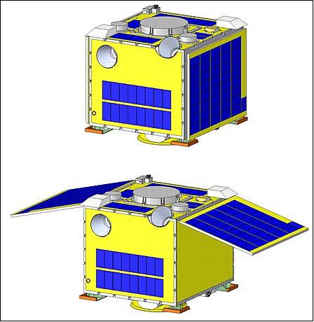
Spacecraft mass, bus size | < 55 kg, 50 cm x 50 cm x 50 cm |
Orbit | Type: SSO (Sun Synchronous Orbit) |
ADCS (Attitude Determination and Control Subsystem) | Method: 3-axis stabilization |
EPS (Electric Power Subsystem) | Solar cells: GaAs multijunction cells, 10 series x 5 parallel x 3 panels |
RF communications | Command link: UHF, 1.2 kbit/s at Sendai station, Japan |
Bus design: The design of the satellite bus system aims to achieve demonstrations of challenging technologies.
• The attitude control system of the satellite achieves accurate attitude control with an pointing accuracy of better than 0.1º, which allows scientific instruments to conduct accurate observations, e.g. of Earth's surface. Many of the sensors and actuators are newly developed based on the in-house technology of the SRL (Space Robotics Laboratory) of the Tohoku University. Some of the sensor units and actuator units are designed in a redundant manner to make the bus system robust to achieve a high reliability. This is indispensable because the performance of the attitude control system directly influences the system survivability.
• The satellite is equipped with two side solar panels to generate an enhanced amount of electrical power which enables long-period observation and/or combinational observation of the payload instruments. Thanks to these side solar panels, the satellite can utilize double the power generation capability than is the case without them. The solar panel hold and deployment mechanisms are going to be newly developed for this purpose and a new structural material is investigated for the side panels to reduce their mass and thickness.
• The spacecraft will be equipped with a DOM (De-Orbit Mechanism) to avoid being space debris after its mission life time. The DOM is based on a thin film deployment mechanism. This will let the satellite reenter into Earth's atmosphere in about 25 years after the activation of this device.
• The unique feature of the bus system is that it is equipped with a micro-monitor camera unit with six micro cameras to view the Earth, to orient the direction where the scientific instruments are pointing at, and to monitor the satellite structure to see if the solar panel deployment and the de-orbit mechanism deployment were successfully executed. This monitoring system is also expected to be quite helpful for the operation of the satellite and scientific observations giving a project a more intuitively understanding of the situation.
• Finally, the bus system is able to accommodate scientific instruments with a total mass of ~ 10 kg, which is about 20% of the spacecraft's total mass. The objective of the bus system is handle the produced large amount of scientific data. For this purpose RISESat is equipped with an X-band data transmitter. Since some scientific instruments require observation on the sun side and some on the dark side of the orbit, RISESat shall able to conduct observations independent of the orbital position. Moreover, for instruments which require long-period continuous observations, such as dosimeter, RISESat can conduct continuous observations through orbits.
Electrical architecture: The electrical system architecture is illustrated in Figure 2. The system consists of payload system and six sub-systems: C&DH (Command & Data Handling), PSS (Power Supply Subsystem), ADCS (Attitude Determination and Control Subsystem), Structures and Mechanisms, TCS (Thermal Control System), and Communication subsystem including the TT&C (Telemetry, Tracking & Command) and the high-speed communication systems. Computational tasks are conducted by distributed processors and FPGAs, which makes the system modular. In this way, the development of each functional unit can be done separately in parallel, and also the interface between the bus system and the payload system becomes properly defined.
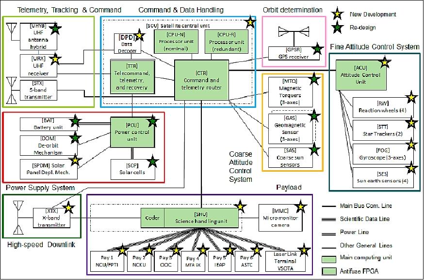
The key design characteristic is that the components which shall have a high reliability are equipped with antifuse FPGA with internal TMR design. The PCU (Power Control Unit) and the TTR (Telecommand, Telemetry, and Recovery) are based on this type of FPGAs. An assumption made is that the PCU is always powered on after the separation from the launcher and does not fail during the operation. The PCU is not equipped with a CPU, all functionalities of the unit are implemented into the hardware logic inside the FPGA. The status of TTR is monitored from the PCU and in case there is no response from the TTR, the PCU conducts power cycling of the TTR. The TTR is the most reliable part of the main computer, SCU (Satellite Central Unit), and deals with the operation of the main processing units: CTR (Command and Telemetry Router) and the nominal and redundant processor boards, which are cold redundant. The TTR is also capable of handling high-priority commands. The SCU is directly connected to the components of the coarse attitude control system.
In safe mode, the ADCS, sensor complement, and the high-speed communication system are turned off. In nominal operation, attitude control unit (ACU) and science handling unit (SHU) are always powered on regardless if the components of fine attitude control system and payload instruments are power on or off.
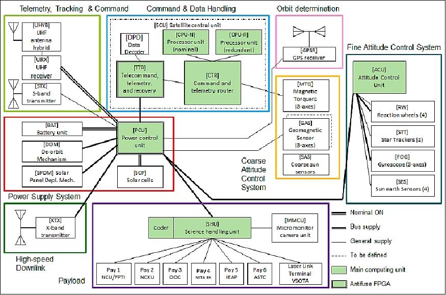
The power distribution architecture is illustrated in Figure 3. The PCU provides the bus supply lines to the main units of each subsystems, such as TTR, ACU, and SHU and these units generate the required voltage levels within the subsystem and distribute them to each component. The PCU is responsible for detecting SEL (Single Event Latchup) events on each supply line and if detected, it breaks the circuit automatically. Only the SCU is powered on automatically after the SEL event. Some components, which require high power consumption or a relatively stable power supply, are connected directly to the PCU. The reaction wheels and the FOG (Fiber Optical Gyro) require bus power supply lines. The magnetic torquers are controlled by the SCU directly.
The interface between the SHU and each scientific instrument are organized in a Space PnP (Plug-n-Play) Avionics (SPA) network. Each group of the scientific instruments has a so called RTU (Remote Terminal Unit) to deal with the interface. These devices are based on technologies provided by ÅAC Microtec, Uppsala, Sweden.
ADCS (Attitude Determination and Control Subsystem): The sensor and actuator components of the ADCS (Table 1) are divided into two groups for different types of attitude controls: coarse and fine attitude controls. The coarse components are those which are necessary for the survival of the satellite system. In these modes, only reliable sensors and actuators are used and many of the satellite components are turned off keeping the total power consumption low in order to charge up the battery. These reliable sensors and actuators are connected with the SCU (Satellite Central Unit) for direct control by SCU. In safe mode, the ACU (Attitude Control Unit) and components for accurate attitude controls are turned off. The latter components are designed for the scientific observation missions with higher pointing accuracy requirements. The dedicated computer ACU is implemented for this purpose and the required components are connected to it. 12)
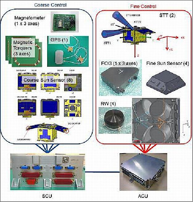
There are three attitude control modes which belong to the coarse attitude control. The first one is the detumbling mode. In this mode, the satellite aims to reduce its relatively high angular velocity. The second one is the safe mode. The system utilizes this mode if the system is in the safe mode. The third one is the idle mode, where the satellite aims to point the solar panels toward the sun in order to effectively generate electrical power. The detumbling and safe modes are achieved by only coarse sun sensors, magnetometers, and magnetic torquers. In addition to these components, the idle mode utilizes Earth sensors as well. The GPS is turned on in default but not used for the coarse attitude control. The pointing accuracy of the coarse attitude control is estimated around 5º.
There are also three fine attitude control modes: nadir pointing mode, target pointing mode, and inertial pointing mode. The nadir pointing mode is used for continuous observation of the Earth surface. The target pointing mode is mainly for observing a certain point fixed on the Earth surface, as well as for high speed mission data downlink. The inertial pointing mode is utilized for observations of celestial target fixed on the inertial frame. For the fine (accurate) attitude control modes, star sensors, reaction wheels, fiber optical gyros, and accurate sun sensors are utilized.
RF communications subsystem: Use of the UHF-band for telecommanding (1.2 kbit/s), the housekeeping data downlink frequency band is in S-band (38.4 kbit/s). For the high-speed mission data downlink, the X-band has been selected with a downlink baud rate of 2.45 Mbit/s. The mission data gathered by the SHU will be transported directly to the X-band transmitter. For this communication mode, the satellite needs to conduct target pointing attitude control at the same time, hence, the total power consumption becomes quite large.
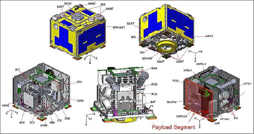
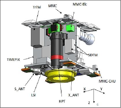
Structure and mechanisms: The internal structural configuration of the RISESAT is illustrated in Figures 5 and 6. The satellite main structure is based on central pillar and outer panel configuration. Both side of one of the four pillar panels are extended to the side panels in order to increase the mounting surface of the bus and the payload instruments, which resulted in an improvement of vibration performance of the whole satellite system relative to the previous micro-satellites of SRL. All outer panels including upper and bottom ones are basically aluminum isogrid panels. This is partly because the CFRP (Carbon Fiber Reinforced Plastic) sandwich structure has less merit in this structural size in terms of their cost and weight, but mainly because aluminum isogrid panel has much better handling performance and flexibility in case one requires modifications.
As for the thermal design concept, most of the on-board equipments are mounted on the main pillar panels and main pillar panels are thermally isolated from the upper and bottom panels.
Launch
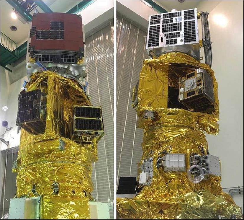
RISESat was launched on 18 January 2019 (00:50 UTC) as a secondary payload on the Epsilon-4 launch vehicle from the JAXA Uchinoura Space Center, Japan. The primary payload on this mission was RAPIS-1 (Rapid Innovative Payload Demonstration Satellite-1), developed at Axelspace. This launch marked the fourth launch of Japan's Epsilon rocket since 2013, and the first Epsilon mission to deliver multiple satellites to orbit. 13)
Orbit: Sun-synchronous orbit, nominal altitude of 500 km, inclination= ~97.3º.
Secondary Payloads
• ALE-1 (Astro Live Experiences-1), a demonstration microsatellite of 68 kg of Astro Live Experiences
• MicroDragon, a microsatellite (50.5 kg) developed by Vietnamese engineers studying in Japan. The microsatellite will be operated by VNSC (Vietnam National Satellite Center).
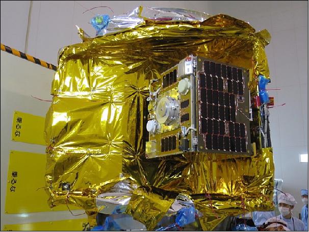
• RISESat, a microsatellite (59 kg) of SRL (Space Robotics Laboratory) of Tohoku University, Sendai, Japan.
• OrigamiSat-1, a 3U CubeSat (4.1 kg) of TiTech (Tokyo Institute of Technology), Tokyo.
• Aoba VELOX-IV, a 2U CubeSat, a joint Singaporean and Japanese nanosatellite mission by Nanyang Technological University, Singapore and the Kyushu Institute of Technology (Kyutech)
• NEXUS (Next Generation X Unique Satellite), a 1U CubeSat designed at Nihon University in collaboration with JAMSAT (Japan AMSAT Association).
Mission Status
• May 2019: At the time of writing, check-out of the satellite bus system is still on-going, including calibration operations for various sensors and verification of the attitude determination and control system performance. DOTCam and the other payloads have been confirmed to be working by powering on, checking the payload housekeeping data, and taking some initial observations – with DOTCam, images of Los Angeles and Taiwan. After checkout of the satellite bus system is completed, the mission experiments of the payloads will begin. 14)
Technical Lessons Learned
The original intent in using the ÅAC Microtec components was to leverage SPA[Space PnP (Plug-n-Play) Avionics] standards to make the science mission subsystem of RISESAT modular, enabling the bus system to be versatile and reusable and facilitating the integration of the payload instruments, while avoiding the ITAR (International Traffic in Arms Regulations) restrictions on SPA technology. ÅAC Microtec in particular offered ITAR-free SPA-compliant components. However, the usage of the key software applications, including the satellite data model (SDM) and the SPA services model (SSM) that replaced it, were ultimately restricted. For some time, the SPA-related software and hardware languished in a regulatory limbo, putting the usage of this technology into question for the RISESAT project. Another key factor in the decision to use ÅAC Microtec SPA-based components was the potential to use the VSI (Virtual System Integration) technology, which would have facilitated integration and test between the payloads and the SHU (Science Handling Unit) remotely. Unfortunately, due to similar restrictions, the development of RISESAT proceeded without using VSI.
Ultimately, "true" SPA interfaces were abandoned in favor of simplified "SPA-inspired" plug-and-play interfaces. The SPA-U interface between the payloads and the SHU became a more standard USB bus, while the SPA-1 interface was maintained. The selfdescribing functionality was replaced by simply hard-programming payload identifiers in the SHU. Even with this adaptation, a certain level of reconfigurability was achieved and proved highly valuable. While assembling the flight model of RISESAT, a hardware issue arose that necessitated the rearrangement of DOTCam's connector to the SHU. Due to the standardized connectors and plug-and-play interface, swapping these ports was trivial. Thus, though the SPA standards could not be utilized as initially intended, plug-and-play functionality was very valuable, especially for the integration of DOTCam.
One lesson learned was that the development of the DOTCam-to-µRTU (or payload-to-ASIM) interface was not to be underestimated. While the physical integration between the two components was simple, since the µRTU had a small form factor and it and its housing could easily be mounted on the payload instrument, the electrical integration and the software development were more demanding. Despite the µRTU being designed to accommodate many possible use cases, DOTCam's parallel data interface necessitated the design of a custom IP core to successfully receive the mission data. DOTCam's SPI also required hardware-level changes to the µRTU SPI IP core. The ability to modify hardware was critical to the payload integration efforts. The development of the µRTU software application also took considerable time, hindered by inadequately detailed documentation. While interface control documents (ICDs) were created and distributed, the level of detail required to make the document truly valuable was underestimated. For example, the DOTCam data interfaces implemented in the FPGA hardware had to be continuously adjusted due to discrepancies and misunderstandings in the timing diagrams. Furthermore, a lack of specificity regarding the power requirements of DOTCam led to an issue with inrush current that resulted in late stage hardware modifications.
Programmatic Lessons learned
The technical challenges encountered were exacerbated in part by various programmatic difficulties. The work of integrating the DOTCam payload to the RISESAT bus was completed by Tohoku University's SRL, with support from NCKU's ISAPS and ÅAC Microtec. These groups represented three different countries, varying levels of experience (from undergraduate students to professors and professional engineers), and numerous different specialties, including aerospace and systems engineering, astrophysics and space sciences, and electrical and software engineering. Understandably, each group had different bases of knowledge, familiarity with different standards and procedures, and different cultural contexts that introduced occasional misunderstandings. Within the SRL team, majority of the payload-to-bus development and integration was conducted by master's students, as one goal of spacecraft development in a university setting is to provide an educational opportunity for hands-on development. Therefore, as with any project driven by students, it was hindered by periodically changing team members (as students graduated), differing levels of experience and engagement, and busy academic schedules.
The distribution of work, particularly regarding the development of the software application of the µRTU, was a particular hindrance. SRL was responsible for this development, which required a thorough understanding of the operation and interfaces of the DOTCam payload. This development would have been more efficient had it been carried out by the DOTCam payload engineers. However, because of schedule constraints, the development of the SHU software application was occurring in parallel and thus, detailed specifications regarding command and data formats and satellite operational procedure could not be provided to the payload teams. Had these specifications been determined and provided to DOTCam engineers, the time for integration could have been minimized. Documentation became a particular point of concern during the latter stages of the development of RISESAT. The project was essentially on hold for a prolonged period after the original launch opportunity could not be realized. During this period, there was a loss of momentum and expertise, as students graduated and engineers moved on to other opportunities. In the meantime, the SPA standards themselves changed and evolved and the component supplier ÅAC Microtec switched its focus to a new product line. Thus, when work began in earnest again, significant time was devoted to relearning and recovery. In hindsight, much of this could have been avoided by extensive documentation.
Payload System
The accommodation envelope for the payload is a key characteristic of the microsatellite. A pillar structure is selected based on the available large spatial resource and technological background at the SRL. The space between the pillar and the side panels is the possible envelope for the instrument installation. To keep the interface simple and to make the system modular, the spaces for bus components and payload instruments are clearly separated as illustrated in Figures 5 and 6. This allows, for example, accommodation of scientific optical instruments with a diameter of about 130 mm at the maximum.
Electrical interfaces and data handling: All payload instruments are controlled and provided with power by the SHU (Science Handling Unit) as illustrated in Figure 9. The telecommands are routed from the SCU (Satellite Central Unit) to the SHU and the housekeeping data of the payload instruments are reported back to the SCU. The SPA-U (Space PnP Avionics-USB) network is applied to the interface between the SHU and the payload instruments.
The data handling of each unit of instruments is being done by dedicated RTUs (Remote Terminal Units). The RTUs receive commands from the SHU and control each instrument unit, as well as reading out the mission data and either forwarding them to the SHU or storing them onto the MMU (Mass Memory Unit). The MMU with non-volatile memories stores the mission data from all payload instruments. The MMU will also perform data pre-processing for the downlink before sending the data to the X-band transmitter.
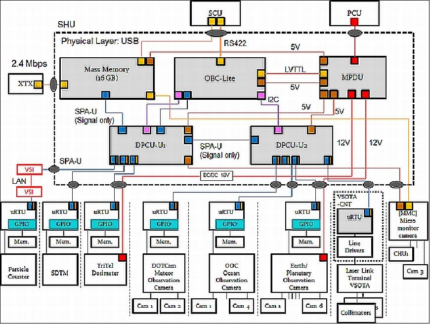
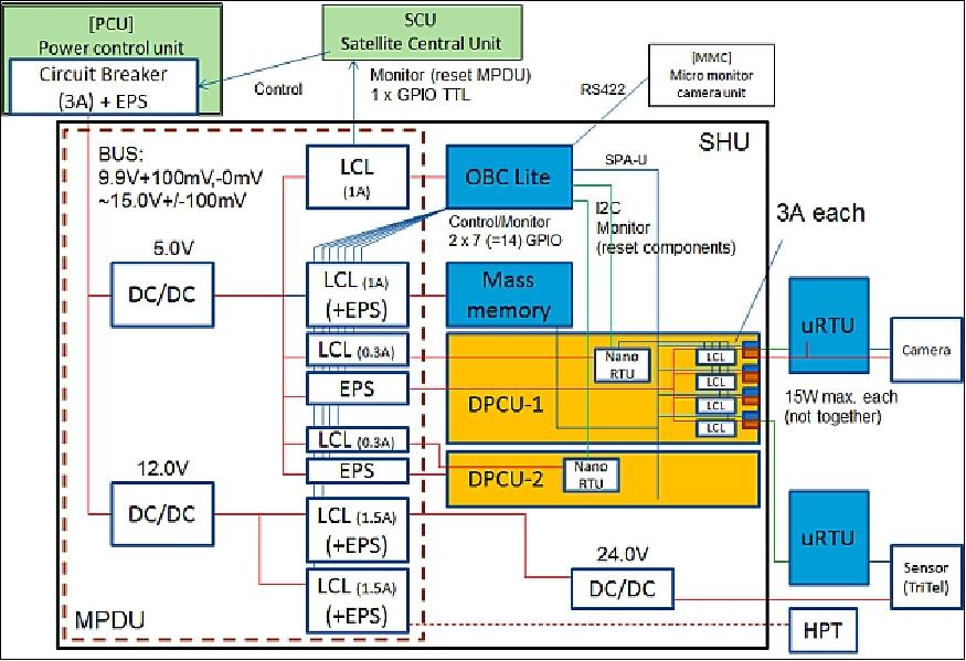
Power management: The MPDU (Main Power Distribution Unit) of the SHU receives a bus power line from the satellite's central PDU (Power Control Unit). The MPDU generates secondary voltages such as 5 V and 12 V for internal use and power supply for payload instruments. For instruments which require other than these voltages, such as TriTel with 15.5 – 35 V, SHU can accommodate up to two custom voltage DC/DC converters inside. The communication lines from the SHU's main computer OBC Lite and the 5 V power supply lines from MPDU are mixed into the SPA standard interface by two DPCUs (Distributed Power Control Units). Each of these DPCUs can have four SPA-U output interfaces. The OBC Lite and the MMU (Mass Memory Unit) are directly powered by the MPDU. One µRTU is assigned to each payload instrument and this unit deals with conversion of SPAU to and from component specific electrical interfaces. All these SPA-compliant components are products of the Swedish company ÅAC Microtec AB.
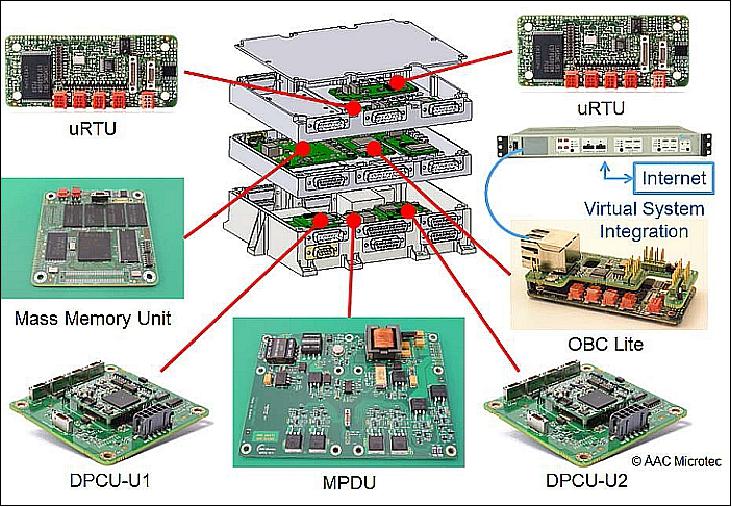
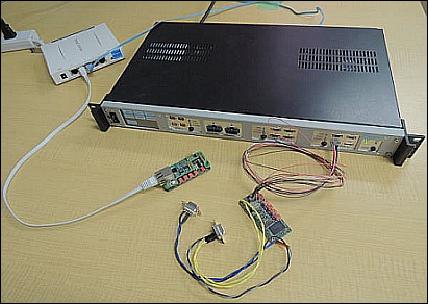
AIT (Assembly Integration and Test): One of the main reasons why the SPA interface was selected for RISESAT is that the combinational use of SPA with VSI (Virtual System Integration) technology allows electrical assembly, integration and tests between remotely located SPA-compatible instruments via Internet. For example, provided that the SHU is integrated with the rest of the satellite and is located in Japan, a payload instrument, developed and located overseas, can be electrically integrated and their system integration test can be done remotely. This technology is quite useful when it comes to international scientific microsatellite projects to accelerate the progress of the project and possibly to reduce component's transportation costs and time between participating institutions. A scenery of virtual system integration is illustrated in Figure 13.

Sensor Complement
HPT (High Precision Telescope)
The HPT of RISESat inherits the technology implemented in the RISING-2 mission ; however, the RISING-2 microsatellite hasn't been launched so far, a launch is planned for 2013. HPT is equipped with two separate LCTFs (Liquid Cristal Tunable Filters) in overlapping wavelength ranges. The step size of the filter is about 1nm and the required time for switching wavelengths is about 10 to 300 ms. Each LCTF is combined with a CCD matrix detector, providing a pixel resolution of 5 m from an altitude of 700 km. With this combination, multispectral images can be obtained.
The LCTF detection concept, which is polarization sensitive, makes it possible to measure the optical properties of solar radiation reflected from land and sea surfaces. The LCTF can be tuned to any desired wavelength by a computer command within its spectral range.
Type of optics | Cassegrain reflective telescope |
Aperture, focal length | 100 mm diameter, 1000 mm (f/10) |
LCTF filters | 420-700 nm |
Spatial resolution | 5 m @700 km altitude |
FOV (Field of View) | 3.3 km x 2.5 km |
Exposure time | > 1/40000 s |
RISESAT utilizes the HPT for both Earth and astronomical observations. In the Earth observation mode, RISESAT will use either nadir pointing or target pointing modes. In case of target pointing mode, RISESAT is able to take multispectral images of the target area.
The HPT data for astronomical and Earth observations are being processed and analyzed Tohoku University and by the partner: National Central University (Taiwan).

DOTCam (Dual-band Optical Transient Camera)
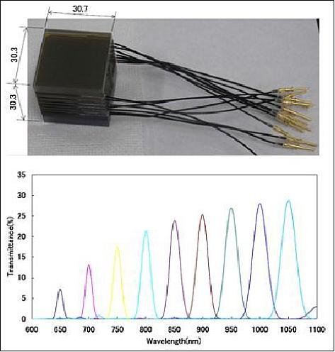
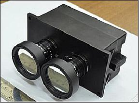
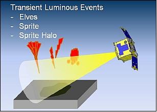
DOTCam is a camera system developed by NCKU (National Cheng Kung University) of Taiwan. The objective is to observe TLEs (Transient Luminous Events) in Earth's upper atmosphere. With the combination of selected wavelengths, DOTCam can detect different kinds of TLEs based on on-board image processing technology. RISESAT conducts Earth Limb pointing mode during the DOTCam operation as illustrated in Figure 17. The operation is limited to the eclipse side of the orbit.
Instrument (Ref. 8):
• Watec T065 CCD, with 659 x 494 pixels, pixel pitch size of 7.4 µm x 7.4 µm
• Lens: focal length=12 mm, F/1.4
• FOV: 22º x 16.5º @ 800 km
• Power: 1 W, 5 V
• Mass: 800 g; size: 108 mm x 70 mm x 100 mm
• Data compression ratio > 2.5
• Modes: continuous acquisition, time-tagged snapshot, single color trigger, two colors trigger.
OOC (Ocean Observation Camera)
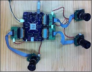
The OOC is a multi-band WFOV (Wide Field of View) camera system in the VIS range designed for ocean surface observation. The spatial resolution is about 100 m in a swath width of about 65 km. This camera system will sweep the ocean surface in a continuous image acquisition mode. The main target area of OOC will be in Asia around Japan and Taiwan; the data can be used in support of the environment and for the fish industry. The EM (Engineering Model) of the OOC is under development.
The OOC instrument is SPA (Space Plug & Play) compatible (Ref. 8).
• Watec T065 CCD, with 659 x 494 pixels, pixel pitch size of 7.4 µm x 7.4 µm
• Lens: focal length=12 mm, F/1.4
• Power: < 3 W, 5 V
• Mass: ~1 kg
TriTel (Three-dimensional Telescope)
TriTel is an advanced dosimetric instrument developed by the Centre of Energy Research of MTA (Hungarian Academy of Science), Budapest, Hungary , in cooperation with BL-Electronics Ltd. The instrument contains three mutually orthogonal, fully depleted, passivated implanted planar silicon detector pairs, accompanied by a stack of printed circuit boards for signal and data processing. The objective of TriTel is to measure energy deposits of charged particles to identify the LET (Linear Energy Transfer) spectrum and the quality factor of cosmic radiation; it has almost a uniform sensitivity in 4π. Aboard RISESAT, TriTel will investigate the spatial and temporal distribution of the cosmic radiation field in LEO (Low Earth Orbit). 15)

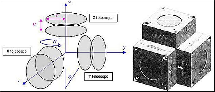
The 3D telescope geometry is shown in Figure 20. The detectors forming the telescope are fully depleted, PIPS (Passivated Implanted Planar Silicon) detectors having an effective area of 222 mm2 and provided by Canberra Packard Central Europe GmbH. The thickness of the depletion layer is 300 µm. The separation between the detectors (p) in one telescope axis is 8.9 mm which means a geometric factor of 5.1 cm2sr for one axis.
The signal of only one of the two detectors – the measuring detector – for a given axis will be analyzed, while the other – the so-called gating detector – will be used only by the corresponding coincidence circuit. After amplification and pulse shaping, the signals are digitized with 16 bit 1.33 Msample/s ADCs (Analog Digital Converters). The 128-channel quasi-logarithmic deposited energy spectra are then produced by a MCA (Multi-Channel Analyzer) realized in a Xilinx Spartan-3 FPGA (Field-Programmable Gate Array).
TRITEL can provide data with a time resolution of 1 minute for count rate measurements (time spectra), and a time resolution of 10 minutes for spectrum acquisition (dosimetry measurements). The coincidence energy spectra produced by the MCA are then used to obtain the LET spectrum due to the pathlength limitation provided by the telescope geometry. The evaluation software then converts the LET spectrum to an average quality factor. The final output of the system will be the dose equivalent. Although the instrument cannot determine the arrival direction of the individual particles, due to the three-axis arrangement an assessment of the angular asymmetry of the trapped radiation might be possible.
Timepix (Space Radiation micro-Tracker)
Timepix is a device developed at the IEAP CTU (Institute of Experimental and Applied Physics of the Czech Technical University), Prague, Czech Republic. The scientific objective is to characterize the mixed radiation field, namely the entire charged particle spectrum from energetic electrons, protons, up to relativistic cosmic-ray ions. The instrument consists of two Timepix pixel detectors, assembled into a single device. The original Timepix was developed within the scope of research carried out within the frame of the Medipix Collaboration; each detector has its own readout interface which is derived and was constructed from the SpaceWire readout interface Satpix for ESA (European Space Agency). 16) 17) 18)
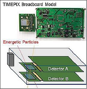
The goal of Timepix is to provide detailed spectral and temporal information of each component of the space radiation field, as well as the direction of trajectories of energetic particles. The results will serve as direct inputs for space weather and solar radiation studies, as well as studies of single event effects in electronic and satellite equipment and health hazards to the crew of manned missions. The detector board of the Timepix and the internal configuration of the sensor are illustrated in Figure 21.
Timepix instrument (Ref. 8):
• High resolution and high sensitivity voxel detector which can directly determine the entire charged particle spectrum from electrons, protons and up to relativistic heavy ions
• Based on the stack of position-sensitive semiconductor detector Timepix, which works as a radiation micro-telescope. The detectors consist of an array of 256 x 256 pixels with 55 µm pitch distributed over area of 2 cm2. Each cell is connected to the corresponding pixel on the 300 µm thick silicon sensor.
• Each pixel is equipped with its own integrated spectrometric signal chain which allows in any pixel to count the number of particles, measure the energy deposited or register the time of interaction.
The block diagram for one detector device consists of FPGA-based DAQ and power board, one Timepix detector chip and chipboard and necessary connectors (Figure 22). Both detectors communicate and are powered via the µRTU (micro Remote Terminal Unit) interface. The whole payload is small ( size of 50 x 100 x150 mm3) with a mass of < 0.5 kg (mostly due to the payload metal casing), requires a single 5 V DC supply, consumes no more than 5 W of power, and produces ~12 kB/s of data, which amounts to ~1.2 GB/day.
The whole device will be preconfigured by per-pixel configuration matrices stored in the µRTU. The device operates in a stand-alone default configuration which is pre-programmed or can be modified by an uplink command. The data, taken in the form of so-called frames, will be time-stamped to allow correlations with the satellite position and eventual correlation with other spacecraft.

Timepix provides noiseless detection of single radiation quanta, measure their energy, position, and time of interaction. Thanks to the detector's high granularity and per-pixel energy sensitivity, the stopping power of single particles can be directly measured in addition to registering and visualizing particle tracks in the pixelated sensor with particle type sensitivity.
Using a single-layer Timepix detector, the direction of trajectory of energetic particles can be determined with an angular resolution of a few degrees. By coupling two sensitive layers into a pixel stack device, a particle micro-tracker is constructed which operates as a particle telescope with high sensitivity tracking and high resolution directional detection of all energetic charged particles (Figure 23) i.e., electrons, muons, pions, protons, light and heavy ions. Also X-rays and even neutrons can be detected – when equipped with neutron convertors. The device will provide a sky mapping of energetic charged particles with high spatial resolution (~0.1º).

Legend to Figure 23: The radiation micro-tracker consists of two Timepix pixel detectors (left) from which the spatial direction of the particle trajectories can be measured (right).
µMAG (micro-Magnetometer)
µMAG is a MEMS-based magnetic field detector developed by ÅAC Microtec, former ÅSTC (Ångström Space Technology Centre) of Uppsala University, Uppsala, Sweden. The detector has a size of 38 mm x 8 mm x 7 mm with a housing box of 60 mm x 10 mm x 9 mm. The sensor has three channels for 3D measurement with a bandwidth of 0 – 1 kHz. The amplification can be switched between two modes and the sensor can measure the magnetic field either in the range of ±1 µT with a resolution of 1 nT and/or ±100 µT with a resolution of 100 nT. One sensor assembly will be mounted atop the deployable panel. The breadboard model of the sensor and mock-up model of the sensor assembly are illustrated in Figure 24.

VSOTA (Very Small Optical TrAnsponder)
VSOTA is an optical communications terminal developed at NICT (National Institute of Information and Communication Technology), Tokyo, Japan. The VSOTA project is part of an advanced bi-directional SOTA (Small Optical TrAnsponder) for microsatellites. The SOTA device of NICT is flown on the microsatellite SOCRATES. However, since SOTA cannot be carried in RISESAT (mass limit), the project decided to build a new, simple, and low-mass equipment which is suitable for RISESAT, namely VSOTA. The goal of NICT and Tohoku University is to realize an on-orbit technology demonstration of one-way optical communication (downlink of payload data) by means of VSOTA from RISESat to a ground station as the first step. 19) 20)
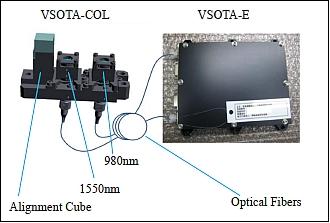
VSOTA features two channels at wavelengths of 980 and 1550 nm, with an output power of 540 mW and 80 mW, and with transmit beam diversion angles of 3.5 mrad and 1.3 mrad, respectively. The electronics unit and the collimators are connected with individual optical fibers (Figure 26). VSOTA's basic structure of Laser Collimator and LD driver are the same as SOTA. In other words, VSOTA is a transmit-only system. Moreover, there is not a gimbal for changing the direction of transmitting laser. Therefore, in order to direct the laser beam to the desired direction, i.e. toward the ground station, it is necessary to change the attitude of RISESAT. This mode of attitude control is called as "Target Pointing Mode". In this mode, +z plane in the satellite body fixed frame (the plate whose normal is along with light axis of RISESAT) are maintained toward the ground optical station. Whether the laser beam from RISESAT can be detected by the ground station or not depends on the beam width, the accuracy of attitude control, and the accuracy of the VSOTA axis and the normal of the +z plane.
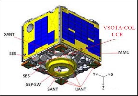
The specification of VSOTA is provided in Table 3. VSOTA consists of two parts; i.e. VSOTA-COL and VSOTA-E (Figure 26). VSOTA-COL has two LDs (Laser Diodes) with different wavelength. There is also an alignment cube on the base plate of VSOTA-COL. Using this alignment cube, direction of light axis of LDs can be measured precisely. VSOTA-E is the electric part which consists of the transmitter laser diode control unit. The internal structure of RISESAT is shown in Figure 27. VSOTA-COL is attached on the +z plate and VSOTA-E is attached on +x plate. These two units are connected by the optical fibers.
Parameter | VSOTA | SOTA |
Mass | < 1 kg | 6.2 kg |
Power consumption | < 10 W | 40 W |
Link range (max) | 2000 km | 2000 km |
Wavelength (Tx) | 980 nm | 980 nm |
Wavelength (Rx) | - | 1064 nm |
Data rate | 1-100 kbit/s | < 10 Mbit/s |
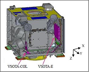
The collimator assembly is fixed to the satellite structure, therefore it is required that RISESat conduct target pointing attitude control mode to point the both collimators toward the Earth optical ground station. With the attitude control capability of the RISESAT, communications with a data rate of 100 kbit/s or more can be achieved using a receive telescope with a diameter of 1.5 m. In the case of SOTA, the beam angle and beam pointing direction can be fine-controlled inside SOTA. The goal of RISESat is to achieve a pointing accuracy of 0.04º (3σ) to be able to demonstrate optical communications with a mobile optical ground station featuring a relatively small diameter.
The concept of the optical communications experiment is shown in Figure 28 . Three types of ground station will be used in this experiment: (1) 1.5 m telescope at Koganei Japan, (2) 35 cm telescope at Kashima, Japan, and (3) a portable telescope with an aperture of ~ 20 cm. The telescopes at Koganei (1) & Kashima (2) are operated by NICT. The portable telescope (3) has been developed by Tohoku University.
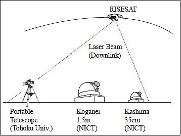
The HPT (High Precision Telescope) onboard RISESat will also be utilized to determine the direction of the pilot signal sent from the ground station, which can be fed back to the attitude control system for achieving higher control accuracy. The desired maximum bitrate for this mission is 1 Mbit/s. NICT's 1.5 m diameter optical ground station is the primary ground station, supported by 0.3 m diameter mobile optical ground stations. This is the first step toward the establishment of future optical communication infrastructures.
In short, VSOTA is capable of transmitting a NRZ waveform on/off keying signal with a maximum 1Mbit/s, however, due to the limitation in pointing direction accuracy, output power, and ground equipment, the maximum downlink rate of VSOTA is estimated to be up to a couple of 100 kbit/s or less. VSOTA can transmit the PN pattern signal for BER evaluation, as well as the real scientific data obtained by scientific instruments. The dual-band (980nm/1550nm) laser signal transmitter with a power of 270 mW and 40 mW, respectively, at modulation allows the project to monitor the difference of the atmospheric effect simultaneously. All payload instruments are controlled and provided with power by the SHU (Science Handling Unit). The SPA (Plug-and-Play Avionics) network is applied to the interface between the SHU and the payload instruments including VSOTA. The data handling of the unit is done by a dedicated RTU (Remote Terminal Unit). VSOTA-CNT is equipped with a µRTU, which receives commands from the SHU and control VSOTA-E via an interface board. The SHU is equipped with a mass memory to store the large amount of mission data from all payload instruments. The SHU will also perform data pre-processing for the downlink before sending the data to the X-band transmitter, as well as forwarding them to VSOTA.
Figure 25 also illustrates the installation point of a CCR (Corner Cube Retro reflector) developed by NICT of which optical axis is the same as of VSOTA and of HPT . HPT and CCR are used as evaluation method of attitude control of RISESat during and before an optical communication experiment.
CCR can be used to detect the satellite when the attitude of RISESat shifts from the nominal position by several degrees. Moreover, from the high precision ranging data, the orbit of RISESat can be determined more precisely. The precise orbit leads to a more accurate ephemeris which can be used for optical communications.
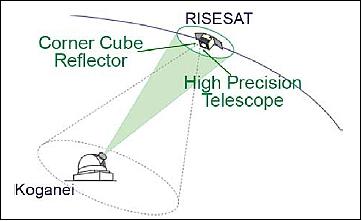
Combination of VSOTA and HPT: To evaluate the performance of body pointing, one method uses the combination of the Laser transmitter of the NICT ground station and the HPT onboard the RISESat. From the Koganei station,a laser beam (532 nm) for SLR (Satellite Laser Ranging) is discharged towards RISESat. Using HPT, which is attached on the same plane as VSOTA-COL, the laser beam from Koganei can be detected. From the position of the light spot in HPT's field of view, for which the attitude of RISESat can be estimated. The concept of this method is shown in Figure 29.
HPT and attitude control: The HPT of the RISESat, designed as a science instrument, will be utilized for both Earth and astronomical observations. It is equipped with two LCTF (Liquid Cristal Tunable Filters) in continuous wavelengths of which the step size is as small as 1nm. Each LCTF is combined with a CCD matrix image sensor with a pixel resolution of 5 m at an altitude of 700 km. With this combination, one can obtain multispectral images. In the Earth observation mode, RISESat will conduct either nadir pointing or target pointing modes. In case of the target pointing mode, RISESat is able to take selected spectral images of the target area with a FOV of 3.3 km x 2.5 km. In this FOV, wavelengths different from the ones for the optical communication experiment, as a guide beam from the optical ground station, and the optical image focal plane should be recorded above background noise moving around due to the attitude control variation in the target pointing mode.
Moreover, the position of pilot laser in FOV can be used by the ACU ( Attitude Control Unit) by recognizing the brightest spot in the CCD coordinates using FPGA logic and software in µRTU. Figure 30 shows a block diagram of the mechanism to do it.

DPD (Data Packet Decoder)
DPD is a store-and-forward device designed for global environmental monitoring, e.g. of carbon distribution. RISESat inherits this technology of the microsatellite WEOS (Whale Ecology Observation Satellite) and will provide an infrastructure of gathering uplinked in-situ measurement data.
Note: WEOS was launched on Dec. 12, 2002 from TNSC as a secondary payload to the ADEOS-II primary payload of JAXA.
References
1) Kazuya Yoshida, Yuji Sakamoto, Yukihiro Takahashi, Junichi Kurihara, Hiroshi Yamakawa, Atsushi Takada, "A Japanese Microsatellite Bus System for International Scientific Missions," Proceedings of IAC 2011 (62nd International Astronautical Congress), Cape Town, South Africa, Oct. 3-7, 2011, paper: IAC-11.B4.2.10
2) Toshinori Kuwahara, Yuji Sakamoto, Kazuya Yoshida, YukihiroTakahashi, Tetsuya Fukuhara, Junichi Kurihara, "Mission and System of the Earth Observation Microsatellite Rising-2," 8th IAA (International Academy of Astronautics) Symposium on Small Satellites for Earth Observation, Berlin, Germany, April 4-8, 2011, URL: http://media.dlr.de:8080/erez4/erez?cmd=get&src=os/IAA/archiv8/
Presentations/IAA-B8-1404-1.pdf
3) Toshinori Kuwahara, Kazuya Yoshida, Yuji Sakamoto, Yoshihiro Tomioka, Kazufumi Fukuda, Masahiro Fukuyama, Yoshihiko Shibuya, "International Scientific Micro-satellite RISESAT based on Space Plug and Play Avionics," Proceedings of the 26th Annual AIAA/USU Conference on Small Satellites, Logan, Utah, USA, August 13-16, 2012, paper: SSC12-I-1, URL of paper: http://tinyurl.com/q5hq42e ; URLof presentation: : http://digitalcommons.usu.edu/cgi/viewcontent.cgi?
filename=0&article=1014&context=smallsat&type=additional
4) Toshinori Kuwahara, Kazuya Yoshida, Yuji Sakamoto, Yoshihiro Tomioka, Kazufumi Fukuda, Yoshihiko Shibuya, "Space Plug and Play Avionics for Small Satellites," Proceedings of the 63rd IAC (International Astronautical Congress), Naples, Italy, Oct. 1-5, 2012, paper: IAC-12-B4.7A.5
5) Toshinori Kuwahara, Kazuya Yoshida, Yuji Sakamoto, Junichi Kurihara, Yukihiro Takahashi, Atsushi Takada, Hiroshi Yamakawa, "Development Status of Microsatellite RISESat, Hodoyoshi-2," Proceedings of the UN/Japan Workshop and The 4th Nanosatellite Symposium (NSS), Nagoya, Japan, Oct. 10-13, 2012
6) Toshihiro Kubo-oka, H. Kunimori, T. Fuse, H. Takenaka, M. Toyoshima, T. Kuwahara, K. Yoshida, Y. Tomioka, K. Fukuda, J. Kurihara, Y. Takahashi,"Collaboration of ranging and optical communication mission RISESAT," URL: http://cddis.gsfc.nasa.gov/lw18/docs/papers/Posters/13-Po08-Kubooka.pdf
7) "Japan plans more amazing microsatellites - Part 2 ," Aug. 16, 2011, URL: http://japaneseinspace.blogspot.com/2011/08/japan-plans-more-amazing_16.html
8) Toshinori Kuwahara, "International Scientific Mission of Microsatellite RISESat - Hodoyoshi-2," 3rd Nano-Satellite Symposium, Kitakyushu, Japan, Dec. 12-13, 2011, URL: https://web.archive.org/web/20190121122203/http://www.nanosat.jp/3rd/sozai_report/Day_2_0105_Toshinori_Kuwahara_Tohoku_University/NSS-03-Day_2_0105_Toshinori_Kuwahara.pdf
9) Yuji Sakamoto, Yukihiro Takahashi, Kazuya Yoshida, Kazufumi Fukuda, Toshihiko Nakano, Steve Battazzo, Tetsuya Fukuhara, Junichi Kurihara, "Development of the microsatellite RISING-2 by Tohoku University and Hokkaido University," Proceedings of the 61st IAC (International Astronautical Congress), Prague, Czech Republic, Sept. 27-Oct. 1, 2010, paper: IAC-10-B4.2.12
10) Yoshihiro Tomioka, Kazuya Yoshida, Yuji Sakamoto, Toshinori Kuwahara, Kazufumi Fukuda, Nobuo Sugimura, Masato Fukuyama, Yoshihiko Shibuya, "Establish the environment to support cost-effective and rapid development of microsatellites," Proceedings of the 63rd IAC (International Astronautical Congress), Naples, Italy, Oct. 1-5, 2012, paper: IAC-12-D1.6.4
11) Toshinori Kuwahara, Yoshihiro Tomioka, Kazufumi Fukuda, Nobuo Sugimura, Yuji Sakamoto, Kazuya Yoshida, Yukihiro Takahashi, Junichi Kurihara, "Space Plug and Play Compatible Earth Observation Payload Instruments," Proceedings of the 9th IAA Symposium on Small Satellites for Earth Observation, Berlin, Germany, April 8-12, 2013, paper: IAA-B9-1502
12) Toshinori Kuwahara, Kazufumi Fukuda, Yoshihiro Tomioka, Masato Fukuyama, Yuji Sakamoto, Kazuya Yoshida, "Attitude Control System of International Scientific Micro-Satellite RISESAT," Proceedings of the 29th ISTS (International Symposium on Space Technology and Science), Nagoya-Aichi, Japan, June 2-8, 2013, paper: 2013-f-30
13) Stephen Clark, "Japan's Epsilon rocket launches seven tech demo satellites," Spaceflight Now, 18 January 2019, URL: https://spaceflightnow.com/2019/01/18/japans-epsilon-rocket-launches-seven-tech-demo-satellites/
14) Hannah Tomio, Morokot Sakal, Shinya Fujita, Toshinori Kuwahara, Alfred Bing-Chih Chen, Ted Wei-Tai Liu, Mike Chih-Chen Tsai, "Lessons Learned from Integrating the Dual-band Optical Transient Camera to Microsatellite RISESAT," Proceedings of the 12th IAA Symposium on Small Satellites for Earth Observation, Berlin, Germany, 06-10 May 2019
15) Toshinori Kuwahara, Attila Hirn, Istvan Apathy, Laszlo Bodnar, Antal Csoke, Sandor Deme, Tamas Pazmandi, Peter Szanto, Gabor Troznai, Balazs Zabori, "TriTel-JMS: A Three-dimensional Silicon Detector Telescope Dedicated for Operation on Board Microsatellite RISESAT," Proceedings of the 29th ISTS (International Symposium on Space Technology and Science), Nagoya-Aichi, Japan, June 2-8, 2013, paper: 2013-r-47
16) Zdenek Vykydal, Michael Holik, Vaclav Kraus, Stanislav Pospisil, Jaroslav Solc, Daniel Turecek, "A Highly Miniaturized and Sensitive Thermal Neutron Detector for Space Applications," Proceedings of AIP (American Institute of Physics) Conference, Quito, Ecuador, July 18-22, 2011, Applications of Nuclear Physics, Vol. 1423, 2012, pp.393-396, doi: 10.1063/1.3688833
17) Carlos Granja, Michal Platkevic, Daniel Turecek, Vaclav Kraus, Michael Holik, Jan Jakubek, Zdenek Vykydal, Stanislav Pospisil, Toshinori Kuwahara, "Miniaturized Radiation Micro-Tracker Timepix for the Scientific Microsatellite RISESAT," Proceedings of the 29th ISTS (International Symposium on Space Technology and Science), Nagoya-Aichi, Japan, June 2-8, 2013, paper: 2013-r-46
18) Michal Platkevič, Carlos Granja,"Timepix-based Miniaturized Energetic Radiation Telescope Spacecraft Payload for the Microsatellite RISESAT," CSO (Czech Space Office, 14 January 2015, URL: http://www.czechspace.cz/en/spacecraft-payload-space-radiation-micro-tracker
19) Hiroo Kunimori, Toshihiro Kubooka,Tetsuharu Fuse, Hideki Takenaka,Morio Toyoshima, Toshinori Kuwahara, Kazuya Yoshida, Yoshihiro Tomioka, Kazufumi Fukuda, Junichi Kurihara, Yukihiro Takahashi, "Down link optical communication experiment using micro satellite body pointing and collaboration with co-located science instrument," Proceedings of the 64th International Astronautical Congress (IAC 2013), Beijing, China, Sept. 23-27, 2013, paper: IAC-13-B2.2.8
20) Toshihiro Kubo-oka, Hiroo Kunimori, Hideki Takenaka, Tetsuharu Fuse, Morio Toyoshima, "Optical Communication Experiment Using Very Small Optical TrAnsponder Component on a Small Satellite RISESAT," Proceedings of the ICSOS (International Conference on Space Optical Systems and Application) 2012, Ajaccio, Corsica, France, October 9-12, 2012, URL: http://icsos2012.nict.go.jp/pdf/1569603383.pdf
The information compiled and edited in this article was provided by Herbert J. Kramer from his documentation of: "Observation of the Earth and Its Environment: Survey of Missions and Sensors" (Springer Verlag) as well as many other sources after the publication of the 4th edition in 2002. - Comments and corrections to this article are always welcome for further updates (eoportal@symbios.space).
Spacecraft Launch Mission Status Payload Sensor Complement References