Rising-2 (Raijin-2)
EO
Atmosphere
Cloud particle properties and profile
Cloud imagery
Quick facts
Overview
| Mission type | EO |
| Agency | Tohoku University |
| Mission status | Mission complete |
| Launch date | 24 May 2014 |
| End of life date | 24 May 2019 |
| Measurement domain | Atmosphere |
| Measurement category | Cloud particle properties and profile |
| Measurement detailed | Cloud imagery |
| CEOS EO Handbook | See Rising-2 (Raijin-2) summary |
Rising-2 (Raijin-2)
Spacecraft Launch Mission Status Sensor Complement Ground Segment MEVIµS
References
Rising-2 is a cooperative microsatellite project of Tohoku University (Sendai) and Hokkaido University, Sapporo, Japan. The primary objective of the mission is Earth observation with a resolution of ~ 5 m. In particular, high-resolution cumulonimbus scenes will be observed using the LCTF (Liquid Tunable Multispectral Filter) technique. The secondary objective is the observation of sprite phenomena in the upper atmosphere. Sprites are so-called TLEs (Transient Luminous Events), which are rather frequent natural phenomena induced by lightning discharges. 1) 2) 3) 4) 5) 6) 7) 8)
The Rising-2 project started in July 2009 and inherited the experiences gained in the design and development of the SpriteSat (Rising-1) spacecraft which was launched on January 23, 2009. The Rising-2 microsatellite is expected to be completed in the summer of 2013.
Spacecraft
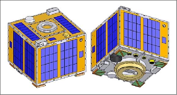
The spacecraft structure is cubical with a side length of 50 cm and a launch mass of ~43 kg, developed at Tohoku University. The central pillar configuration is inherited from SpriteSat, using an aluminum alloy material for the central pillar and the side panels. The spacecraft is 3-axis stabilized.
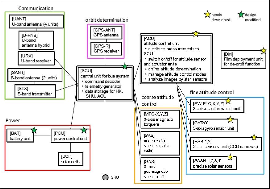
ADCS (Attitude Determination and Control Subsystem): The ADCS uses star and sun sensors, gyros and magnetometers for attitude sensing (Honeywell HMC2003). Actuation is provided by a reaction wheel assembly and 3 magnetorquers (MTQs). The observation requirements call for a spacecraft pointing accuracy of < 0.1º and an angular velocity accuracy of 0.02º/s. 9) 10) 11) 12) 13)
The ADCS offers two observation modes:
• Fine pointing control mode: This is the observation mode which is used for ~ 15 minutes in the sunlit phase of the orbit and for about 15 minutes in the ecliptic phase of the orbit (use of star sensor and reaction wheels).
• Coarse control mode: In this mode, the ADCS sensors idle - the power is turned off for most of the ADCS elements to save energy for the active orbit phases. Six solar cells are being used as SAS (Coarse Sun Sensors), their output is sent to the SCU where the coarse attitude control is taking place.
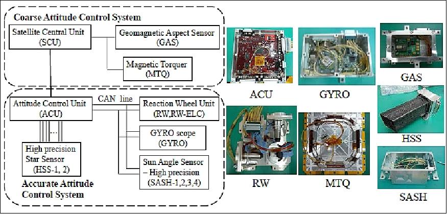
Figure 2 shows the block diagram of the ADCS. The coarse attitude control system consists of the SCU (Satellite Central Unit), the GAS (Geomagnetic Aspect Sensor) and the 3-axis MTQ (Magnetic Torquers). In this system, the geomagnetic field is measured using the GAS, and the body angular velocity damps using the MTQs.
The fine attitude control system consists of ACU (Attitude Control Unit, 3-axis RW (Reaction Wheel), 3-axis Gyro (Gyroscope), 2 star sensors (HSS), and 4 sun sensors SASH ( Sun Angle Sensor – High precision). In this system, the body angular velocity is measured using Gyro. The quaternion is detected using the HSS. The ACU calculates the control torque and sends the command to the RW. The ACU acquires the current time from the SCU, and sends the internal data as status data and telemetry to the SCU. The commands sent from the ground station via SCU are processed using the ACU for the changing of the target direction or the attitude control parameter.
EPS (Electrical Power Subsystem): EPS uses surface-mounted GaAs solar cells for power generation (efficiency of 24%). Four solar panels are mounted on the circumference of the spacecraft (each 8 series x 4 parallels), and one solar panel is mounted on the top side (8 series x 2 parallels). An average power of 42 W is provided. The 9-cell NiMH battery has a capacity of 3.7 Ah (10.8 V). During observations, the spacecraft requires 28.4 W of power while only 7.8 W are needed during non-observation periods. 14)
From the lessons learned of SpriteSat, the EPS has been newly designed and tested. The new design uses an idea of peak power tracking with careful understanding of the characteristics of the solar cells and NiMH batteries.
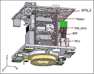
C&DH (Command and Data Handling) subsystem: The 4 controller units in the bus system are the SCU (Satellite Central Unit, ACU (Attitude Control Unit), SHU (Science Handling Unit), and the PCU (Power Control Unit). The SCU is the main unit of the C&DH subsystem. The ACU, SHU, and the PCU are connected to SCU like spokes. Each unit features an FPGA (Field Programmable Gate Array) and CPU (Figure 3). The SCU has two FPGAs (antifuse and flash) and a CPU. The peripheral units are a magnetometer (GAS), sun sensors (SAS), a GPS receiver (GPS-R), a MEMS attitude measurement unit (TAMU), a U-band receiver (URX), and a S-band transmitter (STX). The antifuse FPGA in SCU has the only reboot function of flash FPGA.
The ACU has a flash FPGA and a CPU. The peripheral units are star CCD sensors (HSS-1,2), a gyro sensor (GYRO), high-precision sun sensors (SASH-1,2,3,4) and a reaction wheel unit (RW). The image taken by HSS is processed in the embedded CPU included in the FPGA of the ACU, and the attitude can be determined. The attitude sensors except HSS are connected by a CAN bus interface. 15)
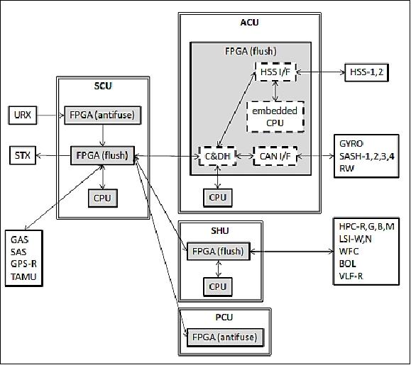
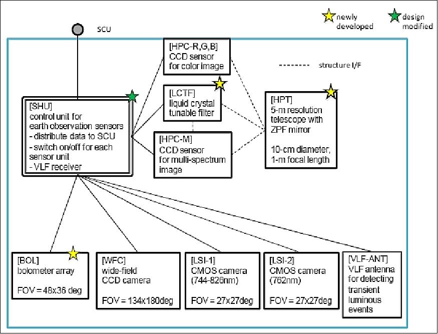
The SHU has a flash FPGA and a CPU. The peripheral units are the telescope CCD sensors (HPC-R,G,B,M) and the sprite CMOS sensors (LSI-W,N), a fish-eye CCD sensor (WFC), a bolometer array sensor (BOL), and a VLF receiver (VLF-R).
The PCU has an antifuse FPGA without a CPU. The functions are battery charge / discharge control, and peak power tracking (PPT) control for power generation of the solar cells. The control parameters can be modified by uplink commands.
All control units feature A/D (Analog-to-Digital) converters, and the house-keeping (HK) data such as voltage, current, and temperature, are measured in each unit. The status data are sent to the SCU.
Unit | IC | Type | Product Name |
SCU (Satellite Central Unit) | FPGA | Antifuse | Actel RTSX32SU-CQ84B |
ACU (Attitude Control Unit) | FPGA | Flash | Xilinx XC4VFX12-10FFG668I (Virtex4) |
SHU (Science Handling Unit) | FPGA | Flash | Altera EP3SL70F780I3 (Stratix-III) |
PCU (Power Control Unit) | FPGA | Antifuse | Actel RTSX32SU-CQ84B |
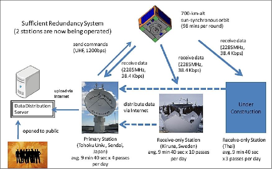
RF communications: The S-band is used for downlink data transmissions at 38.4 kbit/s (max). The uplink data rate is 1.2 kbit/s in UHF. The Sendai station, located on the campus of the Tohoku University, is being used for the uplink and downlink services. Further downlink stations are located in Kiruna, Sweden and in Thailand.
Spacecraft mass, size | 43 kg, cube of ~500 mm side length |
ADCS (Attitude Determination and Control Subsystem) | - 3-axis stabilization |
EPS (Electrical Power Subsystem) | - Solar cells: GaAs multijunction cells (24% efficiency) |
RF communications | Uplink: UHF, data rate of 1200 bit/s |
Launch
The Rising-2 microsatellite was launched as a secondary payload on May 24, 2014 (03:05 UTC) on a H-IIA F24 vehicle (No 24) from the Yoshinobu Launch Complex at TNSC (Tanegashima Space Center), Japan. The launch provider was MHI (Mitsubishi Heavy Industries, Ltd.). The primary payload on this flight wa the ALOS-2 spacecraft of JAXA. 16)
The secondary missions manifested on the ALOS-2 mission by JAXA were: 17)
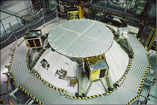
• SPROUT (Space Research on Unique Technology), a nanosatellite of ~7 kg of Nihon University, Tokyo, Japan.
• Rising-2, a cooperative microsatellite (43 kg) project of Tohoku University (Sendai) and Hokkaido University, Sapporo, Japan.
• UNIFORM-1 (University International Formation Mission-1), a microsatellite (~50 kg) of Wakayama University, Wakayama, Japan.
• SOCRATES (Space Optical Communications Research Advanced Technology Satellite), a microsatellite (~ 50 kg) mission of NICT (National Institute of Information and Communications Technology), Koganei, Japan.
Orbit: Sun-synchronous near-circular sub-recurrent orbit, altitude = 628 km, inclination = 97.9º, period = 97.4 minutes, revisit time = 14 days, number of orbits/day = 15 3/14, LSDN (Local Sun time on Descending Node) = 12:00 hours ± 15 min.
Mission Status
• In February 2018, the RISING-2 microsatellite is operating nominally in its 4th year on orbit (Ref. 18).
• In April 2017, the RISING-2 microsatellite is operating after nearly three years on orbit. 18)
• November 8, 2016: The RISING-2 spacecraft and its sensor complement are operating nominally. 19)
• January 20, 2015: The RISING-2 microsatellite has recently succeeded in high-resolution spectral imaging of the earth's surface using the HPT (High Precision Telescope) incorporating the world's first liquid crystal tunable filter for space applications. 20)
- A map was created of the Earth's surface at a resolution of approximately 10 m based on NDVI (Normalized Difference Vegetation Index) indicating the distribution and activity of vegetation derived from images captured at multiple monochromatic wavelengths. Monochromatic imaging technology at this resolution, with the ability to select from a few hundred wavelengths, is a world-first in satellite observations, even for large satellites.
- High-resolution spectral imaging opens the way to measure forests—data gathered forms the basic data for CO2 emissions trading— as well as monitor areas of disasters or pollution with high accuracy, and also allows for AI (Agricultural Informatics) to achieve higher efficiency and higher quality, and also begets highly energy-efficient fishing.
- The satellite proved successful in high-resolution spectral photography of the earth's surface using the world's first liquid crystal tunable filter for space applications incorporated in the high-precision telescope, and in creating a map of the earth's surface at a resolution of approximately 10m based on a NDVI derived from images observed at multiple monochromatic wavelengths.
• The Rising-2 spacecraft and its payload are operating nominally in December 2014. 21)
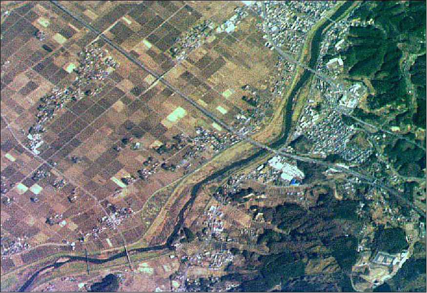
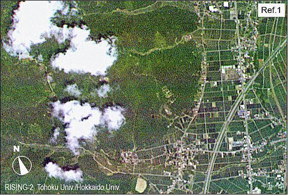
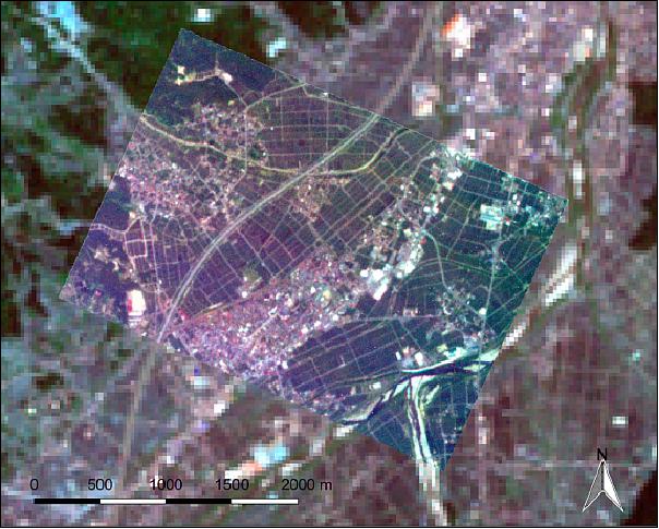
• On July 2, 2014, the Rising-2 project succeeded in observing a detailed landscape in sunny spells during the rainy season. Figure 14 is an image of size 3.2 km x 2.2 km at a resolution of ~5m, acquired to the south in Minamiuonuma City in southern Niigata Prefecture. 22) 23)
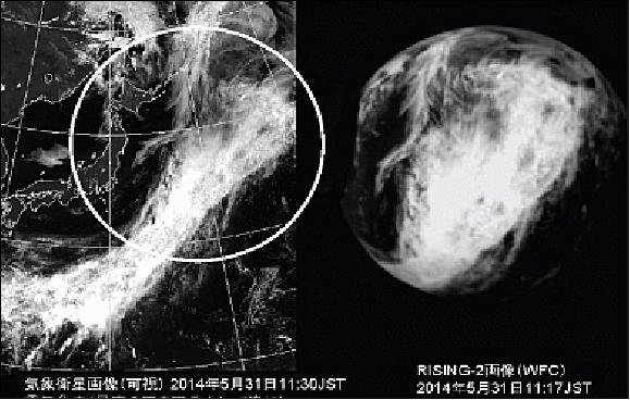
• May 31, 2014: Rising-2 has succeeded in daylight imaging of cloud patterns, and night-time imaging, with a fish-eye CCD camera (WFC) as shown in Figure 15. For comparison, the image is shown side-by-side with a visible image taken by the weather satellite MTSAT (Himawari). The same cloud formation is observed in both images. A circle with a radius of 1,000 km is added as a guide to the meteorological image. 24)
Sensor Complement
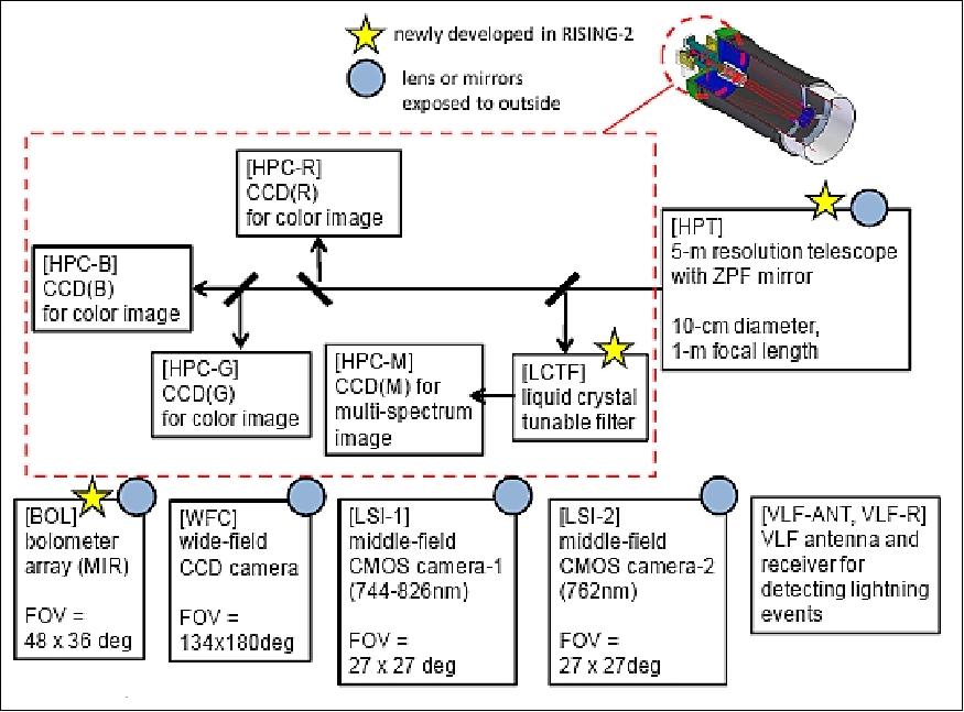
The sensor complement consists of five scientific instruments and some subsystems: two CMOS cameras with different color interference filters, a CCD camera with fish-eye lens, and a VLF radio wave receiver.
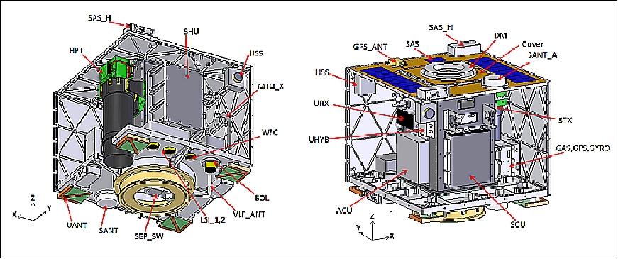
The relationship diagram of sensor complement is shown in Figure 27. Five lenses and a mirror are exposed to the outside of the spacecraft. The newly developed items are HPT and BOL. The other instruments have been already developed in SpriteSat and other previous projects.
HPT (High Precision Telescope)
The HPT is being used to collect the incoming radiation for a particular observational target region. In the case of the sunlit orbit phase, the HPT is generally pointed in the nadir direction to collect high-resolution surface imagery. During the eclipse phase of the orbit, the HPT will be pointed toward targets of opportunity. The main objective is to observe TLEs (Transient Luminous Events).
A study was published by Hokkaido University and Tohoku University of Japan covering the topic of high spatial resolution multispectral imagers, providing an overview of the past decades and a description of the RISING-2 mission within this scenario. 25)
The introduction of nanosatellites and microsatellites technologies in the field of Earth observation is of particular interest. These remote sensing platforms have a great potential because of the cost-effective implementation of satellite constellations and formations, which increase their overall temporal resolution and ground coverage.
However, nano- and microsatellites have many limitations related to their small size, which lead to restrictions on their payload instruments in terms of design, power consumption, and data rate. For optical remote sensing, the spatial and spectral resolutions of an optical payload instrument are limited primarily by its aperture size, which is constrained by the dimensions of the satellite. For any optical system, irrespective of whether it is a spaceborne or ground-based instrument, its spatial resolution is limited theoretically by the diffraction of light, and its spectral resolution is limited practically by the SNR (Signal-to-Noise Ratio). Both the diffraction and the SNR can be upgraded with larger apertures; thus, nano- and microsatellites have fundamental disadvantages compared with larger satellites in terms of optical remote sensing
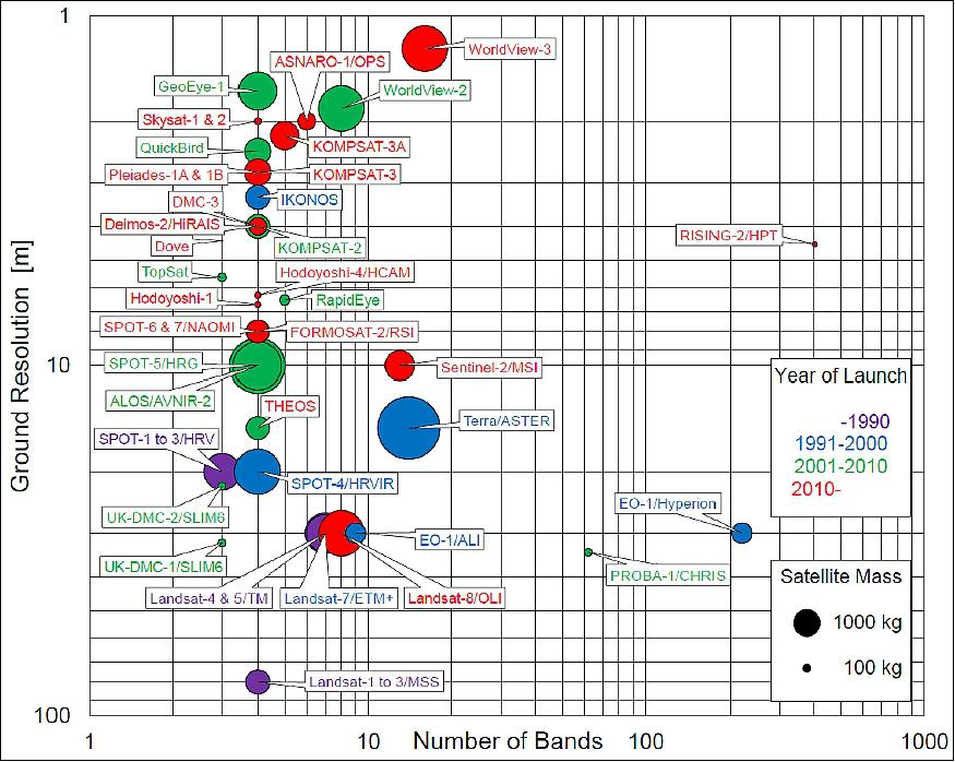
Figure 16 shows a diagram of the distribution of high (<10 m) and moderate (10–100 m) spatial resolution multispectral Earth observation satellites/sensors launched in the previous few decades. The mass of a satellite and the decade of its launch are indicated by the area and the color of the circle, respectively. As can be seen, satellite sensors with three or four spectral bands show a trend toward higher ground resolutions and smaller satellite sizes. Another evident trend is the increase in the number of spectral bands for a series of large satellites, such as the Landsat and WorldView flagship series.
Aside from the multispectral Earth observation satellites, only two satellites, EO-1 (Earth Observing-1) of NASA with Hyperion and the PROBA-1 (Project for On-Board Autonomy-1) of ESA with CHRIS (Compact High Resolution Imaging Spectrometer), are experimentally equipped with high spatial resolution hyperspectral sensors, although additional operational hyperspectral missions are planned for launch before 2020. 26)
The RISING-2 project selected the LCTF (Liquid Crystal Tunable Filter) technology implementation for their payload on the microsatellite to provide a high spatial resolution multispectral imaging capability for the HPT (High-Precision Telescope) instrument, developed by Hokkaido University.
LCTFs use electrically controlled liquid crystal elements to select a specific visible wavelength of light for transmission through the filter at the exclusion of all others. The method relies on constructive and destructive interference effects in a multi-layer stack of quarter-wave reflective layers and half-wave spacer layers. This type of filter is ideal for use with electronic imaging devices, such as CCDs (Charge Coupled Devices), because it offers excellent imaging quality with a simple linear optical pathway.
To the best of our knowledge, the HPT is the first spaceborne sensor using LCTF technology. The advantages for small satellites in using the LCTF are related not only to the reductions in the size, weight, and power consumption of the sensor, but also to the increased flexibility of the spectral bands and enhanced data volumes. The central wavelength of the spectral bands is electrically tunable for every image acquisition; hence, the data volume could be reduced by choosing appropriate spectral bands for specific purposes. This flexibility allows a single multispectral sensor on a nano/microsatellite to be applied to various remote sensing fields, making it comparable with hyperspectral sensors. As shown in Figure 16, the HPT holds a unique position amongst the current multispectral Earth observation sensors.
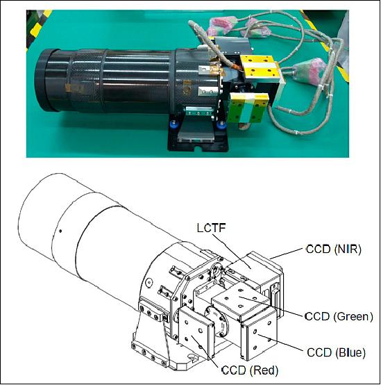
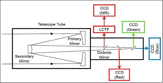
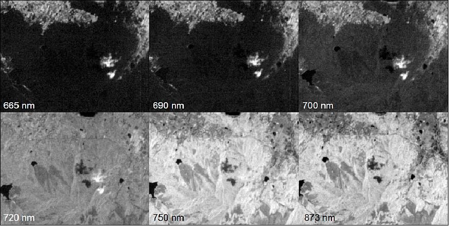
The HPT instrument, installed on the RISING-2 microsatellite is a high spatial resolution multispectral sensor equipped with four CCD (Charge-Coupled Device) imaging sensors for red, green, blue, and NIR (Near Infrared) bands split by dichroic mirrors, as shown in Figures 17 and 18. The LCTF is employed for wavelength scanning only in the NIR band, and it is placed in front of the NIR CCD module. The central wavelength of the NIR band is electrically selectable by controlling the LCTF for every image acquisition; thus, images of the spectral bands that are needed for specific purposes can be acquired sequentially. The specifications of the HPT are listed in Table 3.
Instrument size, mass | 380 mm x 161 mm x 124 mm, 3 kg |
Focal length | 1000 mm |
Aperture diameter | 100 mm |
GSD (Ground Sample Distance) | 4.6 m (at nadir from an orbital altitude of 628 km) |
FOV (Field of View) | 0.28º x 0.21º (3.1 x 2.3 km at nadir from an altitude of 628 km) |
Spectral bands | Blue: 400–510 nm |
Image size | 659 x 494 pixels |
Data quantization | 10 bit |
Description of the HPT instrument
The development of the HPT commenced in 2010, with the aim of achieving a high spatial resolution sensor suitable for deployment on a microsatellite for Earth observation. Earth observation has diverse requirements regarding spatial and spectral resolutions according to different fields of application, e.g., agriculture, environmental monitoring, hydrology, and oceanography (Figure 17). A multispectral imager with 5 m spatial resolution can satisfy a wide range of these fields, except for intelligence services, traffic monitoring, and urban development purposes, which mostly require sub-meter resolution. Therefore, the goal of developing a 5 m resolution multispectral imager was envisioned for the HPT. In order to achieve a ground sample distance of 5 m with a pixel size of 7.4 µm from an altitude of 700 km, a focal length of 1 m is required for the optical system of the sensor. Considering the high SNR required for multispectral imaging, an aperture diameter of 100 mm is considered the largest possible for a 50 kg microsatellite. Accordingly, the diffraction-limited resolution on the focal plane of the optical system is 6.4 µm at the 500 nm wavelength. As the diffraction-limited resolution is close to the pixel size, a diffraction-limited optical system is required. This is why the name of the HPT sensor includes the word precision instead of the resolution.
The optical system of the HPT adopts a Cassegrain reflecting telescope that was designed and manufactured by the Genesia Corp. (Mitaka, Japan). It is important in the design of an optical system for any spaceborne multispectral sensor to account for chromatic aberration and thermal stability. Compared with refracting telescopes using lenses, reflecting telescopes using mirrors have the advantage of no chromatic aberration, which is significant for wavelength scanning in a wide spectral range. Minimizing the chromatic aberration of a refracting telescope is possible, but balancing the chromatic aberration correction with thermal stabilization is usually difficult. The adoption of a reflecting telescope enables the development of the optical system to focus on thermal stability.
In addition, the Cassegrain telescope comprises a parabolic primary mirror and a hyperbolic secondary mirror, which create the long focal length required for high spatial resolution imaging, while minimizing the length of the telescope tube by reflecting the light path. The telescope tube is made of carbon fiber-reinforced plastic, which has a very low coefficient of thermal expansion and high stiffness. The mirror is made from zero thermal expansion pore-free ceramics, which is a material developed by Nihon Ceratec Co., Ltd. (Sendai, Japan) for use in semiconductor manufacturing equipment. Although zero thermal expansion pore-free ceramics have an extremely low coefficient of thermal expansion at around room temperatures, active thermal control of the mirrors is impractical for the limited power supply of a microsatellite. Based on the results of thermal simulation analysis, both the tip of the telescope tube and the reverse side of the secondary mirror, which are exposed to the outside of the satellite, are covered by multilayer insulation to maintain the mirrors at room temperature passively. At room temperature, the Strehl ratio of the optical system measured with a laser interferometer is 0.92, which satisfies the criterion for a diffraction-limited system (>0.8).
A monochromatic CCD image sensor module is used for imaging in the four spectral bands. Generally, CCD image sensors consume more power, but are more sensitive than complementary metal oxide semiconductor (CMOS) imaging sensors. The most important characteristic of a CCD image sensor for satellite imaging is a global shutter that can capture the entire frame at the same instant, although many CMOS image sensors use a rolling shutter. The CCD module T065 manufactured by Watec Co., Ltd. (Tsuruoka, Japan) was developed originally for the optical mission payload instrumentation of the SpriteSat. The unit cell size of this CCD module is 7.4 µm x 7.4 µm, and the effective image size is 659 x 494 pixels. The gain and exposure time of the CCD module are changeable from -6 to +36 dB and from 20 µs to 34 s, respectively, enabling the HPT to be applied to a wide range of spectral radiances on the Earth's surface. An important function supported by this CCD module is the external trigger shutter that allows the synchronization of the three CCD modules for the blue, green, and red bands, in order to acquire a true color composite image.
In the HPT of the RISING-2 microsatellite, the LCTF technology was applied for the first time to a spaceborne multispectral sensor through collaboration with the Research Institute for Advanced Liquid Crystal Technology at the Aomori Support Center for Industrial Promotion in Japan. The LCTF is a type of optical band pass filter that uses liquid crystal for the birefringent plates of the Lyot filter, and the LCTF technology has been used for many applications, e.g., agriculture, healthcare, archeology, and art. The LCTF is composed of several stacked layers of liquid crystal sandwiched between crossed polarizers, and the transmission wavelength of the LCTF is controlled by square-wave voltages that are applied to each layer. On the RISING-2 microsatellite, the LCTF and the voltage-controlling circuit are separated into the HPT and the SHU (Science Handling Unit), respectively. The LCTF developed for the HPT (Figure 19) has dimensions of 30.7 mm x 30.3 mm x 30.3 mm, with a mass of 80 g. The power consumption of the voltage-controlling circuit is 0.2 W. These features enhance the compatibility of the LCTF technology with nano- and microsatellites.
The LCTF is used for wavelength scanning in the NIR band, and the central wavelength of the NIR band is electrically selectable at 1 nm intervals from 650 nm to 1050 nm. In terms of the number of spectral bands, the HPT has 401 bands in the NIR. The peak transmittance and the full width at half maximum increase with the central wavelength from 7% and 12 nm (at 650 nm) to 29% and 30 nm (at 1050 nm), respectively. To maintain the LCTF performance over a wide temperature range, a temperature sensor is attached to the LCTF, and the optimum voltages at the measured temperature are applied automatically using a look-up table stored in the voltage-controlling circuit. The response time for switching from one central wavelength to another depends on the temperature and on the combination of wavelengths. For example, the response time at 25ºC ranges from 39 ms (for a switch from 850 nm to 840 nm) to 259 ms (for a switch from 710 nm to 970 nm), and it is slower/faster at lower/higher temperatures, respectively. The exposure of the NIR CCD is designed to start after sufficient time has elapsed for the switching of the wavelengths.
The primary and secondary mirrors of HPT feature ZPF (Zero-expansion Pore-Free) ceramics of Nihon providing low-mass and high-strength characteristics. A new grinding technology is being used in the polishing of the mirror surfaces.
The LCTF device is modified for use on a spaceborne imager. The device is comprised of liquid crystal multi-layer plates. The wavelength is variable with narrow 5 nm bands. The central wavelength can be tuned in the range of > 300 nm with 10 ms.
Why introduction of LCTF (Liquid Crystal Tunable Filter) technology ?
• Reduction in size, mass and power consumption makes it possible to install on a wide variety of platforms for observation
• A multispectral LCTF sensor is comparable to a heavy, expensive hyper-spectral sensor.
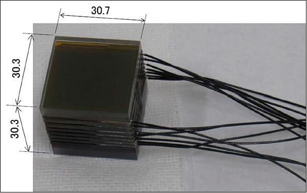
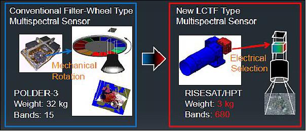
Image analysis methods and results
Color images: A true color composite image is synthesized from red, green, and blue (RGB) band images captured synchronously by the HPT. The fields of view of the three bands deviate spatially from one another because of the optical alignment of their CCD image sensor modules. While the CCD modules are aligned precisely along the optical axis by the focus adjustment, they have an alignment precision of ~100 µm in the direction perpendicular to the optical axis, which corresponds to a deviation of a few tens of pixels. Therefore, band-to-band registration using a feature-based method is implemented in the image processing procedure. The scale-invariant feature transform method is used for feature matching between the blue and green, and between the blue and red band images. From a single set of the two band images for a certain scene, their matched feature points are limited in number, and they are localized within the frame because of the difference in the spectral radiance of the different spectral bands. The matched feature points, which are usually found at the edges of black or white objects and clouds, are accumulated from many sets of different scenes, and a homography matrix is estimated from all of the matched feature points. The homography matrix describes a transformation that maps points in one plane to the corresponding points in another plane, and it is widely used for georeferencing. Based on each estimated homography matrix, the green and red band images are transformed into the coordinate system of the blue band image. Once a sufficiently precise transformation is accomplished, the same homography matrix can be applied to any other RGB band images.
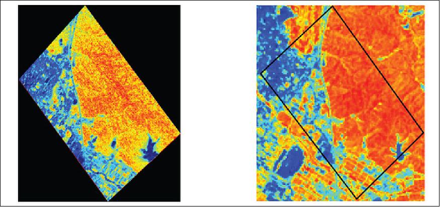
Figure 21 shows a true color image composed of the RGB bands selected from the "first light" scenes, which were acquired about one month after the launch of the RISING-2 microsatellite. For comparison, a true color image composed of Bands 1, 2, and 3 of the ETM+ (Enhanced Thematic Mapper Plus) sensor on the Landsat-7 satellite with 30 m spatial resolution is also shown in Figure 21. The area in the scene is famous for its production of rice in Japan, and many rectangular paddy fields roughly 100 m x 50 m in size are visible in the image. Agricultural roads that are typically a few meters wide, which separate the paddy fields, are evident in the RISING-2 HPT image, but invisible in the Landsat-7 ETM+ image. This image demonstrates clear evidence of the 5 m resolution targeted by the HPT.
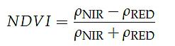
Multispectral images: Multispectral images selectable from 650–1050 nm are acquired with the NIR band of the HPT. A combination of the selected wavelengths is configured in advance, and multispectral images are captured sequentially at a scheduled time and at a specified time interval. Figure 22 shows a series of multispectral images acquired at 665 nm, 690 nm, 700 nm, 720 nm, 750 nm, and 873 nm. The area in these scenes is dominated by forests, whose spectral reflectance is lower at 665 nm and 690 nm (the red region), and higher at 750 nm and 873 nm (the NIR region). Due to attitude fluctuations during the off-nadir pointing of satellite, these scenes deviate from one another spatially. Hence, band-to-band registration using the feature-based method is also required for the processing of the multispectral images prior to the calculation of indices such as the NDVI (Normalized Difference Vegetation Index), which is derived from red and NIR images. The NDVI is calculated from the following expression:
LSI-1 (Lightning Spectrum Imager-1)
The objective is to detect lighting flashes. The camera features a CMOS detector with a format of 512 x 512 pixels. Observations are being made in the spectral band of 744-826 nm. LSI-1 and LSI-2 have a square FOV of 29º corresponding to a ground surface side length of 342 km (Figure 24).
LSI-2 (Lightning Spectrum Imager-2)
The objective is to detect sprites. The camera features a CMOS detector with a format of 512 x 512 pixels.. Observations are made in the spectral band at 762 nm.
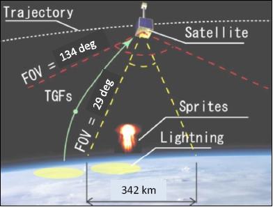
The two LSI cameras are facing nadir during imaging sessions to be able to acquire imagers of the horizontal distribution of lightning and sprite activity. The two imagers use 512 x 512 pixel CMOS detectors creating a field of view of 29º x 29º to allow the imagers to capture ground images of a swath of 342 km at a selectable spatial resolution of 2,400, 1,200 and 600 m. The cameras operate with exposure times of 34.5ms. One of the imagers is equipped with a narrow bandpass filter at 762 nm while the other camera has a broad bandpass of 765-830 nm.
WFC (Wide Field-of-view Camera)
The camera is being used to determine the location of lightning flash which is relating to the TGF (Terrestrial Gamma-ray Flashes) event. This high sensitivity panchromatic CCD camera with a fish-eye lens covers a FOV of 140º.
VLFR (Very Low Frequency Receiver)
The objective of (VLF-ANT, VLFR) is to detect TLEs (Transient Luminous Events).
BOL (Bolometer array camera)
The BOL detector array offers observations in the spectral region of 8-14 m, corresponding to the MWIR (Midwave Infrared) and the TIR (Thermal Infrared) regions. At the 700 km altitude, the spatial resolution is ~ 1 km, which corresponds to 0.076º/pixel. Temperature distribution imagery of such targets as: a cumulonimbus region, a ground surface scene, and a region of the sea surface can be generated.
The following three phenomena can be recognized:
- From the temperature of the top of cumulonimbus, the altitude can be estimated. With the simultaneous observations by LSI and WFC, the relationship of transient luminous events and cumulonimbus is analyzed.
- Observing the temperature distribution of the ground surface, buildings, and the sea, the generation of cumulonimbus can be monitored, which is a resource for determining heavy rain.
- Natural disasters such as wildfires and volcano eruptions will be observed; the objective is to check the applicability of this observation method for rapid detection results.
The commercial bolometer camera is being slightly modified for space observations. The instrument has a power consumption of 8.4 W and a mass of 0.554 kg. During a BOL observation mode, the satellite is rotated in such a way as to avoid solar radiation entering the BOL optics. In the rotation period of the satellite, the power of BOL is turned on, and deep space imagery is taken for calibration purposes. After the attitude has been stabilized and the instruments are pointing into target region on Earth's surface, observations may be started.

Observation Modes
The observation modes of the spacecraft are being conducted in 15 minute periods, where one period is in the sunlit phase of the orbit and the second observation period is in the eclipse phase of the orbit. One of the following 7 modes is being selected and completed in < 15 minutes. In the EPS, the sensor power is defined as 3 W on average. This requires some adjustment of the time for Mode-1 and Mode-5 to avoid a battery degradation.
1) Mode-1: Sprite observation mode (LSI-1,-2, and VLFR), 3.8 W, only in the eclipse phase
2) Mode-2: Lightning observation mode (WFC, and VLFR), 2.8 W, only in the eclipse phase
3) Mode 3: LSI mode (LSI-2), 1.0 W, for cumulonimbus, ground, and sea, generally in the sunlit phase
4) Mode 4: WFC mode (WFC), 1.0 W, for aurora, ground, and sea
5) Mode 5: BOL mode (BOL), 7.8 W, for cumulonimbus, ground, and sea
6) Mode-6: RGB telescope mode (HPC-R, -G, -B), 3.0 W, for cumulonimbus, ground, moon, and planets
7) Multispectral telescope mode (HPC-M, LCTF), 2.0 W, for cumulonimbus, ground, moon, and planets.
Ground Segment
The Tohoku University ground station will be used as the primary station for spacecraft operations. In addition, the ground stations in Kiruna (Sweden) and in Thailand will be used as receiving stations only. The three stations will provide a daily contact time with the spacecraft for ~ 165 minutes.
MEVIµS (Model-based Environment for Verification and Integration of µ-Satellite)
SRL (Space Robotics Laboratory) of Tohoku University developed MEVIµS in parallel with the development of RISING-2 and RISESAT. In this environment, all satellite subsystems are simulated in software based on actual components including attitude control as well as data handling and power control. MEVIµS is based on a realtime OS to realize realtime simulation of HILS (Hardware-in-the-Loop Simulation) environment. HILS of the RISING-2 attitude control system was demonstrated by utilizing the satellite on-board computer and reaction wheels. The star tracker test system was introduced to include the failure detection and time delay. As the results, the system development became more efficient since the attitude control system verification could be carried out all of the time. 28)
From the acquisition of the RISING-2 data in on-orbit operations, the reliability of the development environment will be increased by reflecting the results. Furthermore, it will contribute to produce next micro satellite under development. This paper puts an emphasis on the configuration and capabilities of the HILS environment including star tracker test system.
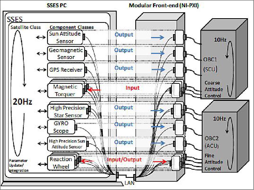
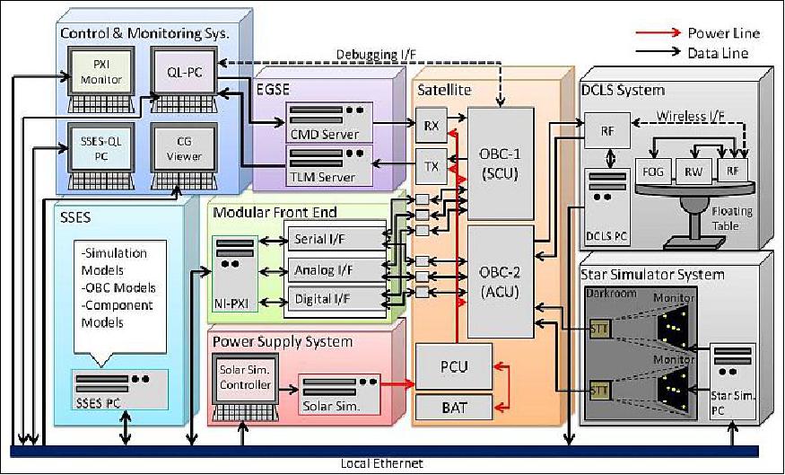
MEVIµS is composed to seven parts: Operation Monitoring System, SSES (Satellite and Space Environment Simulator), EGSE (Electrical Ground Support Equipment), MFE (Modular Front End), Power Supply System, and DCLS (Dynamic Closed Loop Simulator). Figure 7 shows the general view of MEVIµS. All system except the EGSE and the satellite system are connected by a local Ethernet for high speed communication. The SSES and MFE are described which are core elements of MEVIµS.
Outline of SSES: SSES is a software simulator in C++ which constitutes the core of MEVIµS. SSES is composed of a space environment model and a satellite system model, which are separated to maintain the versatility of the simulator.
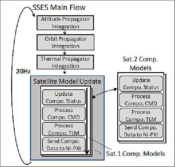
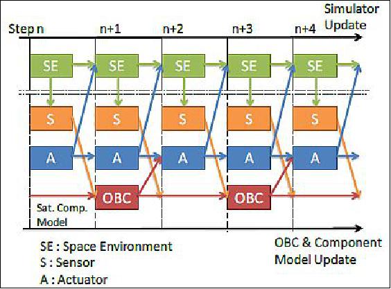
These models are formed by multiple C++ classes. The former model consists of an orbital calculation class,an attitude calculation class, a geomagnetic model class, a solar model class, and a lunar gravity model class. The latter model includes a satellite mathematical component class, for example, an on-board computer class, a sensor class and so on. Each component class is built in a hierarchic structure to match the actual components. This model is exchangeable to adapt for various satellite systems. If another satellite system model is prepared, all simulation can be implemented to utilize the same space environment model. The calculation flow of SSES and the data transfer model are shown in Figure 29.
The operating frequency of SSES is adjustable. The fastest frequency is 20 Hz from an operational test result. SSES is a mathematical simulator including time delay functions of each component (Figure 30). For an ideal mathematical simulation and time delay simulation, the SILS (Software In-the-Loop Simulation) environment consists of the SSES and Operation Monitoring System. In order to establish HILS, the MFE (Modular Front End) is needed.
Outline of MFE (Modular Front End): MFE a data communication system between the satellite hardware components and the SSES. This system is necessary to execute HILS. The MFE is mainly composed of a controller and a data communication interface. To maintain the versatility, because specific IDs for each satellite are prepared, HILS can be constructed without changing the communication protocol of the system. However, electrical interfaces are need ed for each satellite system. The controller of the MFE features a computer-installed realtime OS, to realize the time management in the microsecond range.
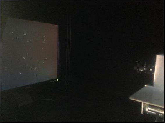
Star Simulator System: The star simulator was developed to test the performance of star trackers in laboratory on the ground. The star simulator overview is shown in Figure 32. Star maps are displayed on an LCD monitor, while the star tracker detects the stars and calculates attitude referred star catalog. The star catalog for the displayed stars can be selected from the Smithsonian Astrophysical Observatory Star Catalog, the Hipparcos catalog, et.al. The star positions on the celestial sphere are calculated from right ascension, declination, and rotation angle of the detector.
Attitude control strategy of RISING-2: Attitude determination systems are divided on fine and coarse attitude determination. The sun sensor and magnetometer data is used for the coarse attitude determination. The star tracker data is used for the fine attitude determination. These systems can be changed automatically if roll and pitch angle error fall below 5º and the yaw angle error is < 10º. As might be expected, it is possible to change these systems by using the change command.
The attitude control modes of RISING-2 are the following:
- NP (Nadir Pointing) mode
- TP (Target of earth-surface Pointing) mode
- DSP (Deep-Space Pointing) mode
At the beginning of pointing control, RISING-2 executes the NP control by the coarse attitude determination in order to stabilize the attitude and enable to detect quaternion by star tracker. RISING-2 keeps a free-rotation state for the non-observation time, because the power capacity of RISING-2 is limited. After stabilizing in NP, the accuracy attitude determination system is selected for improvement of the pointing precision, and the attitude control mode is changed as to observation purposes. In TP mode, the target position is sent from the ground station.
In DSP mode, the observation plane of the satellite is pointed to the light avoidance direction without sunlight, moonlight, and the light reflected from the Earth. This mode is carried out for infrared observation using BOL (Bolometer array). After the DSP mode, NP or TP mode, control is executed while sunlight and moonlight do not enter BOL.
In summary, a star simulator was introduced to MEVIµS for the improvement of the HILS environment. To establish this evaluation environment, it is possible to evaluate attitude control system including the actual characteristic of the star tracker. Moreover, this simulator Verification of the RISING-2 attitude control subsystem was demonstrated by utilizing a pre-flight model in the HILS environment prior to the launch. The attitude control procedures were confirmed and the results contributed for making the actual operation method.
References
1) Yuji Sakamoto, Yukihiro Takahashi, Kazuya Yoshida, Kazufumi Fukuda, Toshihiko Nakano, Steve Battazzo, Tetsuya Fukuhara, Junichi Kurihara, "Development of the microsatellite RISING-2 by Tohoku University and Hokkaido University," Proceedings of the 61st IAC (International Astronautical Congress), Prague, Czech Republic, Sept. 27-Oct. 1, 2010, IAC-10-B4.2.12
2) Kazuya Yoshida, Yuji Sakamoto, Toshinori Kuwahara, Yukihiro Takahashi, "A Series of 50 kg-Class Micro-Satellites for Advanced Science Missions," 8th IAA (International Academy of Astronautics) Symposium on Small Satellites for Earth Observation, Berlin, Germany, April 4-8, 2011
3) Toshinori Kuwahara, Yuji Sakamoto, Kazuya Yoshida, YukihiroTakahashi, Tetsuya Fukuhara, Junichi Kurihara, "Mission and System of the Earth Observation Microsatellite RISING‐2," 8th IAA (International Academy of Astronautics) Symposium on Small Satellites for Earth Observation, Berlin, Germany, April 4-8, 2011, URL: http://media.dlr.de:8080/erez4/erez?cmd=get&src=o
s/IAA/archiv8/Presentations/IAA-B8-1404.pdf
4) Yuji Sakamoto, Yukihiro Takahashi, Kazuya Yoshida, "Development of the microsatellite RISING-2 by Tohoku University and Hokkaido University," Japan Geoscience Union Meeting 2010, Makuhari, Chiba, Japan, May 23-28, 2010
5) https://web.archive.org/web/20210828060202/http://www.astro.mech.tohoku.ac.jp/~rising2/en/
6) Yuji Sakamoto, Toshinori Kuwahara, Yukihiro Takahashi, Kazuya Yoshida, "Progress Report of the Development of microsatellite RISING-2 for cumulonimbus and sprite observation by multi-spectrum," Japan GeoScience Union Meeting 2012, Makuhari, Chiba, Japan, May 20-25, 2012, URL: [web source no longer available]
7) Yoshihiro Tomioka, Yuji Sakamoto, Toshinori Kuwahara, Kazufumi Fukuda, Nobuo Sugimura, Kazuya Yoshida, "Lessons Learned on Structural Design of 50kg Micro-satellites based on Three Real-life Micro-satellite Projects," Proceedings of the UN/Japan Workshop and The 4th Nanosatellite Symposium (NSS), Nagoya, Japan, Oct. 10-13, 2012, paper: NSS-04-0411
8) Toshinori Kuwahara, Kazuya Yoshida, Yuji Sakamoto, Yoshihiro Tomioka, Kazufumi Fukuda, Nobuo Sugimura, Junichi Kurihara, Tetsuya Fukuhara, Yukihiro Takahashi, "Constellation of Earth Observation Microsatellites with Multispectral High-resolution Telescopes," Proceedings of the 27th AIAA/USU Conference, Small Satellite Constellations, Logan, Utah, USA, Aug. 10-15, 2013, paper: SSC13-IV-7, URL: http://digitalcommons.usu.edu/cgi/viewcontent.cgi?article=2938&context=smallsat
9) Kazufumi Fukuda, Toshihiko Nakano, Yuji Sakamoto, Toshinori Kuwahara, Kazuya Yoshida, Yukihiro Takahashi, "Attitude control system of micro satellite RISING-2," 8th IAA (International Academy of Astronautics) Symposium on Small Satellites for Earth Observation, Berlin, Germany, April 4-8, 2011
10) Toshinori Kuwahara, Steve Battazzo, Yoshihiro Tomioka, Yuji Sakamoto, Kazuya Yoshida, "System Integration of a Star Sensor for the Small Earth Observation Satellite RISING-2," Proceedings of the 28th ISTS (International Symposium on Space Technology and Science), Okinawa, Japan, June 5-12, 2011, paper: 2011-d-11
11) Yuji Sakamoto, Toshinori Kuwahara, Kazufumi Fukuda, Kazuya Yoshida, Tetsuya Fukuhara, Junichi Kurihara, Yukihiro Takahashi, "Development Status and Operation Plan of 50-kg Microsatellite RISING-2 for Earth Observations by Multi-Spectrum Instruments," Proceedings of the 28th ISTS (International Symposium on Space Technology and Science), Okinawa, Japan, June 5-12, 2011, paper: 2011-f-25
12) Yoshihiro Tomioka, Toshinori Kuwahara, Yuji Sakamoto, Hironori Fukuchi, Yuta Tanabe, Kazuya Yoshida, "Micro-satellite structure system for cost-effective and rapid development," Proceedings of the 3rd Nanosatellite Symposium, Kitakyushu, Japan, December 12-14, 2011, paper: NSS-03-0411
13) Nobuo Sugimura, Kazufumi Fukuda, Masato Fukuyama, Yoshihiro Tomioka, Toshinori Kuwahara, Yuji Sakamoto, Kazuya Yoshida, Yukihiro Takahashi, "Attitude Control for Earth Observation Microsatellite RISING-2," Proceedings of the 9th IAA Symposium on Small Satellites for Earth Observation, Berlin, Germany, April 8-12, 2013, paper: IAA-B9-0603
14) Yuji Sakamoto, Toshinori Kuwahara, Yoshihiro Tomioka, Kazufumi Fukuda, Kazuya Yoshida, "Evaluation of Power Control System for Micro and Nano Satellites by Hardware-in-the-Loop Simulator," Proceedings of the 26th Annual AIAA/USU Conference on Small Satellites, Logan, Utah, USA, August 13-16, 2012, paper: SSC12-X-8
15) Yuji Sakamoto, Toshinori Kuwahara, Steve Battazzo, Kazufumi Fukuda, Yoshihiro Tomioka, Kazuya Yoshida, "Development Method of Command and Data Handling System for Micro and Nano Satellites," Proceedings of the 3rd Nanosatellite Symposium, Kitakyushu, Japan, December 12-14, 2011, paper: NSS-03-0412
16) "DAICHI-2 (ALOS-2) Status and Orbit Calculation," JAXA Press Release, May 24, 2014, URL: http://global.jaxa.jp/press/2014/05/20140524_daichi2.html
17) Toshinori Kuwahara, Kazaya Yoshida, Yuji Sakamoto, Yoshihiro Tomioka, Kazifumi Fukuda, Nobuo Sugimura, Junichi Kurihara, Yukihoro Takahashi, "Space Plug and Play Compatible Earth Observation Payload Instruments," Proceedings of the 9th IAA Symposium on Small Satellites for Earth Observation, Berlin, Germany, April 8-12, 2013, Paper: IAA-B9-1502, URL: http://media.dlr.de:8080/erez4/erez?cmd=get&src=os/IAA
archive9/Presentations/IAA-B9-1502.pdf
18) Information provided by Dr. Junichi Kurihara of Hokkaido University, Sapporo, Hokkaido, Japan.
19) Kazuya Yoshida, "Robotics for Space Exploration:Challenge to the Moonand Beyond," The Keck Institute for Space Studies, Caltech, November 8, 2016, URL: http://kiss.caltech.edu/new_website/lectures/presentations/Yoshida.pdf
20) "RISING-2 Satellite Succeeds in High Resolution Spectral Imaging," Hokkaido University, Jan. 20, 2015, URL: http://www.oia.hokudai.ac.jp/blog/2015/01/20/71/
21) Junichi Kurihara, Yukihiro Takahashi, "The RISING-2 microsatellite as a pilot program for future multispectral remote-sensing by microsatellites," The 21st Session of the Asia-Pacific Regional Space Agency Forum (APRSAF-21), Tokyo, Japan, December 2-5, 2014, STWG (Space Technology Working Group)
22) "RISING-2 Successfully Takes Ground Surface Image with Highest Resolution in Microsatellite Class," Hokkaido University Press Release, July 16, 2014, URL: http://www.oia.hokudai.ac.jp/blog/2014/07/16/48/
23) "Space Mission Center," Hokkaido University, URL: http://www.cris.hokudai.ac.jp/cris/smc/news_e.html
24) "Satellite RISING-2 Progressing Well in Preparation for Full-Scale Observation," Hokkaido University Press Release, June 24, 2014, URL: http://www.oia.hokudai.ac.jp/blog/2014/06/24/43/
25) Junichi Kurihara, Yukihiro Takahashi, Yuji Sakamoto, Toshinori Kuwahara, Kazuya Yoshida, "HPT: A High Spatial Resolution Multispectral Sensor for Microsatellite Remote Sensing," Sensors Feb. 2018, Vol. 18, No 2, 619; doi:10.3390/s18020619, URL: http://www.mdpi.com/1424-8220/18/2/619/pdf
26) Karl Staenz, Andreas Mueller, Uta Heiden, "Overview of of terrestrial imaging spectroscopy missions," Proceedings of the IEEE IGARSS (International Geoscience and Remote Sensing Symposium), Melbourne, Australia, 21–26 July 2013, pp. 3502–3505, doi:10.1109/IGARSS.2013.6723584
27) Tetsuro Ishida, Junichi Kurihara, Fra Angelico Viray, Shielo Baes Namuco, Enrico C. Paringit, Gay Jane Perez, Yukihiro Takahashi, Joel Joseph Marciano Jr., "A novel approach for vegetation classification using UAV-based hyperspectral imaging," Computers and Electronics in Agriculture, Volume 144, January 2018, pp: 80-85, https://doi.org/10.1016/j.compag.2017.11.027, URL: https://tinyurl.com/y6vczanj
28) Nobuo Sugimura, Yoshihiro Tomioka, Toshinori Kuwahara, Yuji Sakamoto, Kazufumi Fukuda, Kazuya Yoshida, "Verification of RISING-2 Attitude Control System in Generic Hardware-in-the-Loop Simulation Environment," Proceedings of the 65th International Astronautical Congress (IAC 2014), Toronto, Canada, Sept. 29-Oct. 3, 2014, paper: IAC-14, B4, 6A, 12
Spacecraft Launch Mission Status Sensor Complement Ground Segment MEVIµS
References Back to Top