SCATSat-1 (Scatterometer Satellite-1)
EO
Ocean
Mission complete
Scatterometers
Quick facts
Overview
| Mission type | EO |
| Agency | ISRO |
| Mission status | Mission complete |
| Launch date | 26 Sep 2016 |
| End of life date | 25 Mar 2026 |
| Measurement domain | Ocean |
| Measurement category | Ocean surface winds |
| Measurement detailed | Wind vector over sea surface (horizontal) |
| Instruments | Scatterometer (Scatsat-1), Scatterometer (Scatsat-1A) |
| Instrument type | Scatterometers |
| CEOS EO Handbook | See SCATSat-1 (Scatterometer Satellite-1) summary |
SCATSat-1 (Scatterometer Satellite-1)
Spacecraft Launch Mission Status Sensor Complement References
SCATSat-1 is an OceanSat-2 follow-up mission, actually a gap-filler mission between OceanSat-2 and -3, under development at ISRO (Indian Space Research Organization) with the objective to continue the global ocean wind vector data acquisition started by the OSCAT (OceanSat-2 Scanning Scatterometer). The information of global ocean surface winds is an important ingredient for weather forecasts. In particular, a need for global coverage of scatterometer data became evident, when NASA's SeaWinds scatterometer on the QuikSCAT spacecraft ceased nominal operations in November 2009.
The objectives of SCATSat-1 mission are:
• To design, develop, launch and operate a state of art three axis body stabilized satellite providing ocean based remote sensing services to provide continuity of weather forecasting services to the user community.
• To develop a remote sensing capability with respect to global day and night weather forecasting.
• To establish a ground segment to receive and process the payload data at a specified turn around time to meet the requirements of the user community.
• To develop related algorithms and data products at 50 km x 50 km and 25 km x 25 km grids to serve the well-established application areas and also to enhance the mission utility.
Some background: OceanSat-2 of ISRO was launched on September 23, 2009, providing excellent data of its payload when on February 20, 2014, OSCAT experienced an irrecoverable malfunction in its TWTA (Traveling Wave Tube Amplifier) subsystem of the primary chain and of the scan mechanism of the redundant (backup) chain during the end of its design life period (around 4½ years from launch), forcing ISRO to suspend its operation in April 2014. During its operational lifetime, OSCAT had demonstrated the importance and significance of the ocean wind vector data in weather modeling and prediction and laid the ground for continuation of the global ocean surface wind vector data acquisition. The OSCAT data were also used by the international community like NASA/JPL, NOAA, KNMI, EUMETSAT and ECMWF for both research and operational purposes. 1) 2)
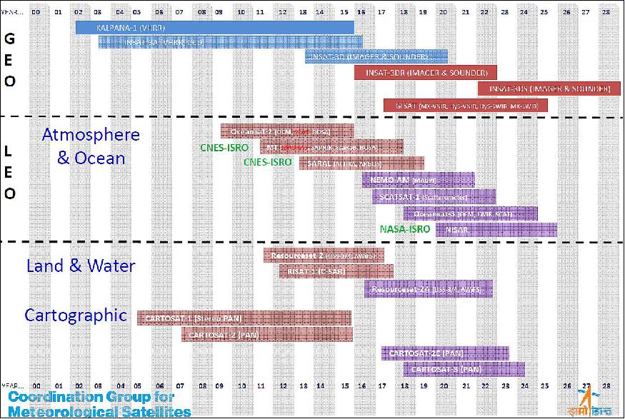
ISRO plans to launch the OceanSat-3 and -3A in the timeframe 2018 and 2019, respectively. The payloads of OceanSat-3 will be OSCAT-2 (Ocean Scatterometer-2), a Ku-band pencil beam scatterometer, OCM -3 (Ocean Color Monitor-3), and SSTM (Sea Surface Temp Monitor), an optical radiometer. OCM-3, which is an improvement over OCM-2, will have thirteen narrow spectral bands in the VNIR (Visible and Near Infrared) region. It will have an improved spectral resolution and SNR as compared to OCM-1/2.
Spacecraft
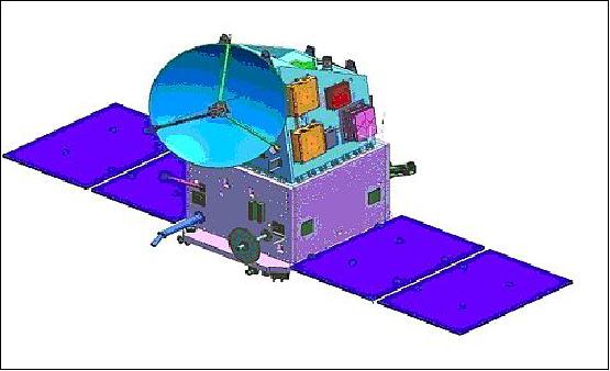
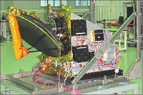
SCATSat-1 is a minisatellite with a mass of ~ 371 kg and a design life of 5 years, configured on the IMS-2 (Indian Mini Satellite-2) spacecraft bus of ISRO. According to Tapan Misra, director of ISRO/SAC, it takes normally about 3 years to build a satellite of this class from scratch. However, the project sourced about 40% of the parts used in SCATSat-1 from spares of previous missions, to complete the development in a year’s time.
• EPS (Electrical Power Subsystem): 2 solar arrays are generating 750 W, 28 Ah Li-ion battery.
• AOCS (Attitude Orbit Control Subsystem): The AOCS uses reaction wheels, magnetic torquers and hydrazine thrusters.
• RF communications: Data transmission in X-band at data rates of 105 Mbit/s. The on-board SSR (Solid State Recorder) has a capacity of 52 GB. S-band communications for command and telemetry data.
• TCS (Thermal Control Subsystem): The TCS is passive using MLI (Multi Layer Insulation) blankets, paints and heat pipe embedded panels.
More spacecraft information will be provided when it becomes available.
Development Status
• As of early 2016, SCATSat-1 is at an advanced stage of realization. All the flight model subsystems have been realized and undergone Test and Evaluation. The final flight model integration and check-out activities of OSCAT-2 are underway. 4)
- The TSU (Temperature Sounding Unit) is not part of this mission.
• As of mid-2015, the SCATSAT-1 project is in an advanced development state. All the subsystems have been realized and all the subsystem level tests are completed. Spacecraft integration is in progress.
Launch
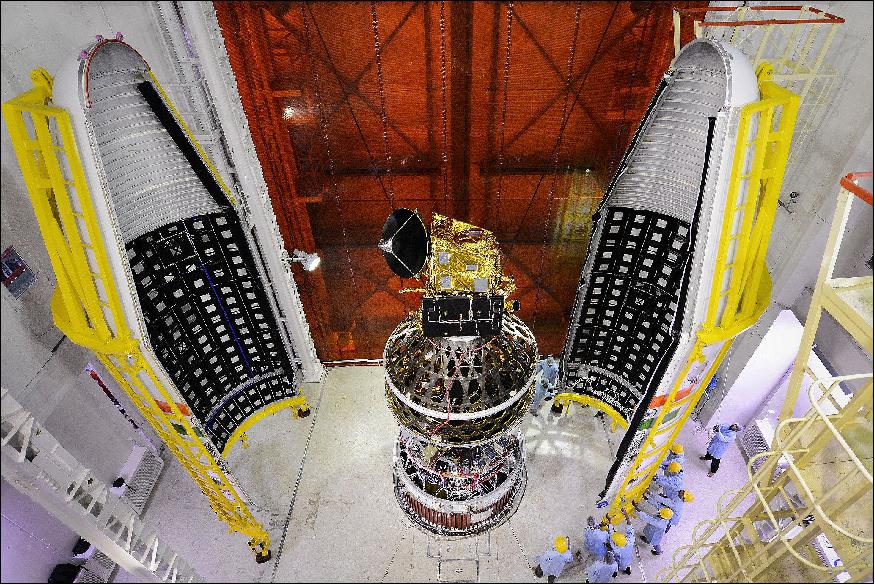
The SCATSat-1 spacecraft was launched on Sept. 26, 2016 (03:42:00 UTC) on the PSLV-C35 vehicle of ISRO. The launch site was SDSC (Satish Dhawan Space Center) on the east coast of India. 5) 6)
Orbit: Sun-synchronous orbit of SCATSat-1, altitude = 720 km, inclination = 98.1º, LTAN = 9:30 hours. The satellite is allowed to drift to an LTAN of 8:45, orbital period of 99.19 minutes.
All secondary payloads were deployed into an orbit of 670 km altitude.
This was ISRO's first multi-orbit mission. It was the longest ever PSLV flight which lasted for more than 2 hours 15 minutes. According to ISRO, PSLV-C35 successfully placed all satellites into their respective orbits.
Secondary Payloads
The secondary payloads (7 co-passengers) on this flight were:
• Pratham, a student-built nanosatellite (~10 kg) of IIT (Indian Institute of Technology) Bombay, India to study the ionosphere.
• PISAT, a student-built nanosatellite (5.3 kg) of PES University in Bengaluru, India. PISAT is a joint initiative of PES University and five other colleges. 7)
• BlackSky Pathfinder-1, a high-resolution (1 m) imaging microsatellite (~44 kg) of BlackSky Global. BlackSky Global is a commercial company of Seattle, WA, USA. The goal of BlackSky Global is to build a constellation of 60 satellites by 2019.
• AlSat-1N, AlSat-1B and AlSat-2B of ASAL (Algerian Space Agency), Algiers, Algeria. The three satellites were manufactured at SSTL partnership with Algerian engineers, ALSAT-1B is a 103 kg microsatellite based on the SSTL-100 bus. It carries an Earth imaging payload with panchromatic and multispectral cameras. AlSat-2B (117 kg) carries the NAOMI (New AstroSat Optical Modular Instrument). AlSat-1N (AlSat-Nano) is a 3U CubeSat which carries a technology demonstration payload as part of a partnership between ASAL and the UKSA (UK Space Agency).
• CanX-7, a nanosatellite (3U CubeSat, 3.5 kg) of UTIAS/SFL (University of Toronto’s Institute of Aerospace Studies/Space Flight Laboratory), Canada.
Mission Status
• November 2020: The Ku-band (13.5 GHz) based scatterometer is the main sensor onboard Scatterometer Satellite (SCATSAT-1) launched on 26th September 2016 by Indian Space Research Organization (ISRO). The SCATSAT-1 satellite sensor provides daily updates on the conditions of atmospheric, oceanographic, agriculture and cryospheric parameters. Moreover, it delivers data products (Level 1-4) in form of different parameters (σο, λο, brightness temperature BT, wind vectors and velocity) at two different polarization modes (HH and VV). Since launch, several studies have been carried out to explore the potential of SCATSAT-1 satellite sensor for remote observation of the ocean as well as the land surface at the global level. Besides the conventional applications in weather and oceanic domains which are based on wind vector data, emerging applications over land use and land cover are also introduced. 8)
• January 24, 2019: ScatSat-1 Wind products from OSI SAF (Ocean and Sea Ice Satellite Applications Facility) will be available on EUMETCast from 7 February 2019. The products are ScatSat-1 25 km (OSI-112-a) and 50 km (OSI-112-b) scatterometer winds, in BUFR and netCDF format. The ScatSat-1 satellite was launched by the Indian Space Research Organisation (ISRO) and carries the OSCAT scatterometer. ISRO kindly provides the near-real time data which are used as input for the OSI SAF wind products. 9)
- The products will be distributed on EUMETCast Europe and EUMETCast Africa.
• March 2017: The SCATSat-1 data are presently being disseminated to the international user community while the initial calibration-validation phase is still continuing. The brightness temperature (TB) data derived from SCATSat noise measurements exhibit close match with collocated AMSR-2 derived 10.65 GHz TB data. The SCATSat-1 observed normalized radar backscatter (σ0) over homogeneous natural calibration target like the Amazon rain-forest is stable within 0.5 dB among all observational variants such as ascending and descending passes (day and night) and fore and aft look directions. 10)
- The histograms of σ0 over ocean accumulated during a repeat cycle show balancing of range-slices within 0.2 dB absolute. The slice-wise plots of percentage of negative σ0 as function of SNR saturate at 50% while the SNR is -30 dB or less, thus, authenticating the accuracy of noise estimation and correction. Another important aspect of the data quality of SCATSat-1 is the linearity of SNR versus σ0 across the entire dynamic range of the sensor, even at SNRs as low as -45 dB. The in-orbit observations exactly replicate the pre-launch characterization. The winds obtained using the first version of SCATSat-1 derived GMF (Geophysical Model Function) have near-zero speed and directional biases with respect to ASCAT-derived winds and the rmse are within 0.5 dB in speed and 150 in direction over the entire dynamic range.
• October 18, 2016: NRSC (National Remote Sensing Center) of ISRO announced the release of wind products (beta version) of the OSCAT-2 instrument. The data products are available to all users from October 19, 2016 onwards. The products will be available in 25 km and 50 km grids, in HDF 5 (Hierarchical Data Format 5) format. Validation of software and products is in progress and operational products will be released shortly. 11)
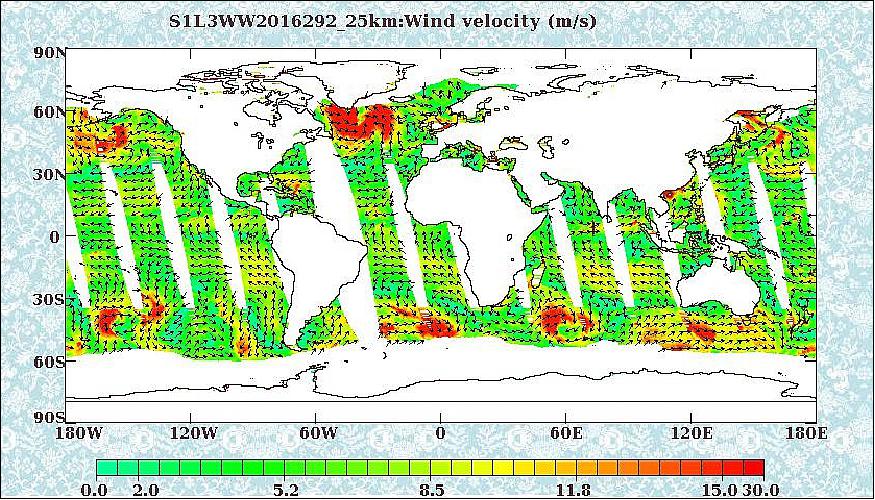
• The OSCAT-2 scatterometer payload was switched on in active mode on October 3, 2016. 12)
- Oct. 3, 2016: Calibration over Antarctica (cal val site) carried out.
- Oct. 1, 2016: Calibration over Rann of Kutch (cal val site) carried out.
- Sept. 30, 2016: Star Sensor -2 performance evaluation has been carried out by selecting it for control for two orbits. Star Sensor-2 made OFF and Star Sensor -1 selected for control. Payload Calibration over Amazon (cal val site) and Deep Space carried out.
- Sept. 29, 2016: SSM (Scatterometer Scanning Mechanism) main mode switched on in Radiometric Mode. Calibration over Greenland (cal val site) carried out. Deep space Calibration carried out.
- Sept. 28, 2016: Radiometric mode Deep space calibration carried out. Radiometric mode Calibration over Amazon (cal val site) carried out. Radiometric mode Calibration over Antarctica (cal val site) carried out.
- Sept. 27, 2016: SSM in Redundant Mode initiated. First payload data downloaded over Antarctica station. Deep space Radiometric calibration operation carried out. Calibration for brightness temperature was carried out over Greenland. (cal val site).
- Sept. 26, 2016: Successfully deployed Solar Panels and Hold Down & Release Mechanism of Scatterometer Antenna. Successfully acquired 3 Axis Attitude stabilization. Scatterometer initial configuration completed.
Sensor Complement
OSCAT-2 (Ocean Scatterometer-2)
The OSCAT-2 instrument onboard SCATSat-1, developed at ISRO/SAC, Ahmedabad, is similar to OSCAT flown onboard OceanSat-2. However, many improvements both in hardware as well as for the onboard signal processor and control software are being implemented, based on the OSCAT experience. The instrument is a pencil beam wind scatterometer operating at Ku-band of 13.515 GHz.
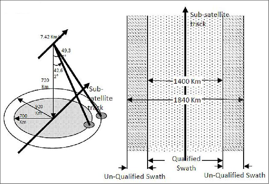
The two pencil beams (conical scanning), inner and outer, result in a constant angle of incidence for both beams; this allows σo measurements at multiple (4 or 2) azimuth angles for the same point on the ocean surface. Each point in the inner swath is viewed twice at different azimuth angles by both beams. The region between the inner and outer swath is subjected to two measurements by only the outer beam, and the wind vector there can only be determined with a directional ambiguity of 180º.
Parameter | Inner beam | Outer beam |
Orbital altitude | 723 km | |
Instrument frequency | 13.515 GHz (Ku-band) | |
Wind speed range | 3-30 m/s, accuracy of 1.8 m/s (rms) or 10% | |
Wind direction | 0º to 360º, accuracy of 20º rms | |
Wind vector cell size (resolution) | 50 km x 50 km grid and 25 km x 25 km grid | |
Polarization | HH | VV |
Swath width | 1400 km | 1840 km |
Scanning circle radius | 700 km | 920 km |
Scanning rate | 20.5 rpm | |
Antenna diameter | 1 m | |
Nominal PRF (Pulse Repetition Frequency) | 193 Hz | |
Transmit pulse width | 1.35 ms | |
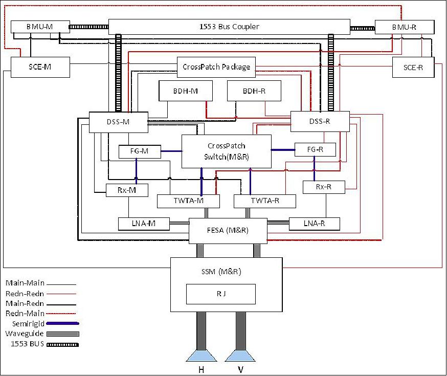
The OSCAT-2 instrument consists of the following subsystems:
1) Digital and RF packages for generating the transmit signal and processing the received echo signal
- DSS (Digital Subsystem)
- FG (Frequency Generator)
- TWTA (Travelling Wave Tube Amplifier)
- FESA-LNA (Receiver Package (Rx) along with front end LNA).
2) Antenna system comprising of the reflector and feed assembly along with RJ (Rotary Joint) and SSM (Scan Mechanism). The SSM is accompanied by SCE (Scan Control Electronics).
3) The integration elements consisting of:
- FESA (Front End Switch Assembly)
- CPS (FG-TWTA Crosspatch Switch)
CPP (SCE-DSS Crosspatch Package).
In order to realize the SCATSat-1 system in a minimum possible time, it was decided to retain the system level specifications of the OSCAT instrument which would facilitate the usage of some of the hardware procured/fabricated for OSCAT-2. Accordingly, the RF subsystems viz., Frequency Generator, TWTA, FESA (Front-End Switch Assembly), Receiver subsystem have been retained/ re-fabricated using the same designs that were carried out for OSCAT. -However, the digital subsystem has been redesigned leveraging some of the recent efforts that have resulted in a smaller form factor for the digital system resulting in hardware reduction, by combining all the digital functions into one subsystem. The photographs in Figures 7 (a)-(f) show the flight models of various critical subsystems realized for SCATSat-1.
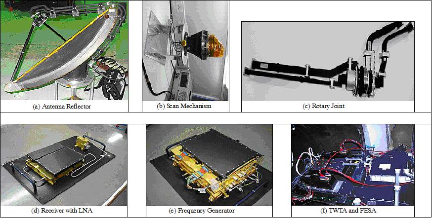
Antenna subsystem: The antenna subsystem consists of a 1m parabolic dish reflector along with two elliptical horns at an offset to the principal focal plane to generate two beams. The entire reflector –feed assembly is spun by a scan mechanism at a constant rate of 20.5 rpm. It also consists of an optical angle encoder which provides the antenna azimuth position with respect to the orbit +ve pitch axis. This angle information is used by the onboard data processing system for Doppler compensation of the incoming return echo signal. The scan motor and the dual channel rotary joint are together housed in the scan mechanism housing. The rotary joint facilitates the routing of the transmit and receive RF signals to the two horns for producing the two beams at a look angle of 42.62º and 49.38º, respectively. Table-3 gives the brief specifications of the antenna subsystem.
Reflector | 1 m diameter parabolic dish |
Number of beams | Two (inner – HH, outer – VV) |
Beamwidth | 1.47º (azimuth) x 1.63º (elevation) for HH beam |
Gain | 39 dBi for both beams |
Scan rate | 20.5 rpm |
RF subsystem: The RF system consists of the FG (Frequency Generator), TWTA, and receiver (Rx) systems which operate in the RF band. The FG and Rx systems are being fabricated using the same designs developed for OSCAT and the TWTAs are the spare units procured for OSCAT.
The FG provides all the RF signals like, LO (Local Oscillator) for the receiver operation, the modulated transmit signal and the clock signals for the digital system operation. All the signals are derived from a single TCXO (Temperature Compensated Crystal Oscillator), a local oscillator of 50 MHz to maintain the coherence of the signal. The LNA section of the receiver, viz. FESA-LNA, is located close to the receive port of the FESA and the receiver units. It has been redesigned with waveguide interface at the input of the LNA in order to improve the noise figure of the system. This new design is expected to give an improvement of approximately 1dB in the noise figure.
DSS (Digital Subsystem): The DSS for the SCATSat-1 has been redesigned to take advantage of the advances in FPGA technology and the new designs that have been carried out in ISRO during the last few years. The redesign resulted in combining all the digital functionalities accomplished by the three subsystems in OSCAT into one subsystem resulting in the reduction of mass, power and real estate on the spacecraft. Various functionalities like the baseband chirp generation is accomplished by DCG (Digital Chirp Generator) in OSCAT-2, control signal generation is accomplished by the PLC (Payload Controller), and data acquisition and onboard processing by DACS (Data Acquisition and Compression Subsystem) are all now combined into one subsystem.
Similar to that in OSCAT, DSS acts as a single gateway for communication and data transmission between the spacecraft and instrument. All the communication is accomplished using a MIL-STD-1553 bus and the echo data is transmitted to the spacecraft using the LVDS (Low Voltage Differential Signaling) bus.
Changes from OSCAT
Orbit: By design, the OSCAT-2 scatterometer onboard SCATSAT-1 and OSCAT (on OceanSat-2) are similar. Hence the scan geometry, look and incidence angles etc., are all the same. The altitude of SCATSat-1 is also the same as that of OSCAT. However, the orbit local time has been changed to 6AM-6PM, which may be revised to accommodate the requirements of the co-passenger during the launch.
Hardware: Apart from the change in the design of the digital subsystem as mentioned above, some changes have been introduced in the OSCAT-2 instrument configuration, based on the experience of OSCAT, in order to improve the reliability of the overall instrument hardware. In OSCAT, the main (prime) and redundant (backup) chains of the instrument were realized as two independent chains, where the scan motor along with its control electronics and all RF and digital subsystems had cold redundancy. Only the rotary joint and the reflector-feed system were the elements common to both the chains. When the TWTA of the main chain had failed, the operation was changed over to the redundant chain. However, the scan mechanism of the redundant chain failed immediately though the TWTA while all other subsystems were in good health. This fact has forced the design team to rethink on the concept of redundancy and accordingly, major changes were introduced to improve the reliability factor through cross patching of the critical subsystems. Accordingly, the following subsystems are being cross-patched using RF and digital level cross-patch packages:
• FG-TWTA, through RF Cross-patch Switch
• DSS-Scan Control Electronics, through cross-patch package
• DSS has the capability to command the TWTA in the alternate chain by utilizing the built-in mechanism.
• Improvement in noise equivalent σ0 of the order of 3 dB over OSCAT, 2-stage digital filter achieving much better passband slope and ripple replacing the analog band-limiting SAW filter at receiver output.
OnBoard Signal Processor: Though the OSCAT has been designed primarily for capturing ocean surface wind vector data, it has been found that the scatterometry data has as well wide applications in sea ice and polar ice studies as demonstrated by both QuikSCAT and OSCAT. It was observed that the OSCAT data was sometimes saturating in the Polar Regions. This has been analyzed and the reason for the this default was found to be that the number of bits, used by the onboard processor for representing the echo data, were not sufficient to represent the signal with very high SNR values coming from the Polar Regions. Hence, the onboard processor has been modified to transmit a 32- bit accumulator count as science telemetry, to avoid the saturation.
• Full 32-bit precision of onboard processed data unlike truncated 16-bit in OSCAT. 4K-FFT replacing 1K FFT (overlapped periodogram approach of OSCAT).
References
1) Information provided by Tapan Misra, Director of ISRO/SAC (Satellite Application Center), Ahmedabad, India.
2) Tapan Misra, Raj Kumar, BS Gohil, Kirti Padia, Prantik Chakraborty, “ISRO’s Scatterometry Program,” IOVWST (International Ocean Vector Winds Science Team) Meeting, Portland OR, USA, May 19-21, 2015, URL: https://coaps.fsu.edu/scatterometry/meeting/docs/
2015/ProgrammaticTalks/ISROsScatterometeryProgramme.pdf
3) Avinash Nair, ”ISRO scientists in Ahmedabad use ‘spares’ for weather satellite to save cost and time,” The Indian Express, Feb. 5, 2016, URL: http://indianexpress.com/article/cities/ahmedabad/
isro-scientists-in-ahmedabad-uses-spares-for-weather-satellite-to-save-cost-and-time/
4) Information provided by Somya S. Sarkar and Tapan Misra, Director of ISRO/SAC, Ahmedabad, India.
5) ”PSLV-C35 / SCATSAT-1, ISRO, Sept. 26, 2016, URL: http://www.isro.gov.in/launcher/pslv-c35-scatsat-1
6) ”PSLV-C35 / SCATSAT-1 Brochure,” ISRO, URL: http://www.isro.gov.in
/pslv-c35-scatsat-1/pslv-c35-scatsat-1-brochure-0
7) ”PISAT nanosatellite ready for space launch in July 2016,” PES News, April 20, 2016, URL: http://news.pes.edu/pisat-nanosatellite-ready-for-space-launch-in-july-2016/
8) Sartajvir Singh, Reet Kamal Tiwari, Hemendra Singh Gusain, Vishakha Sood, et al., ”Potential Applications of SCATSAT-1 Satellite Sensor: A Systematic Review,” IEEE Sensors Journal, Volume: 20, Issue: 21, Published: Nov.1, 1 2020, https://doi.org/10.1109/JSEN.2020.3002720
9) ”ScatSat-1 Wind products from OSI SAF on EUMETCast soon,” EUMETSAT, 24 January 2019, URL: [web source no longer available]
10) Information provided by Somya S Sarkar of ISRO/SAC(Satellite Application Center), Ahmedabad, India.
11) ”SCATSat-1 Products (Beta Version),” ISRO/NRSC, October 18, 2016, URL: http://nrsc.gov.in
/SCATSAT-1_Wind_Products
12) ”Post Launch Updates of PSLV-C35 / SCATSAT-1,” ISRO, 2016, URL: http://www.isro.gov.in
/pslv-c35-scatsat-1/post-launch-updates
13) ISRO Report on the Status of Current and future satellites,” Presented to CGMS-44, WP-01 Plenary Session, ISRO, June 5-10, 2016, URL: http://www.eumetsat.int/website/wcm/idc/idcplg?
IdcService=GET_FILE&RevisionSelectionMethod=LatestReleased&Rendition=Web&dDocName=CWPT_1792
The information compiled and edited in this article was provided by Herbert J. Kramer from his documentation of: ”Observation of the Earth and Its Environment: Survey of Missions and Sensors” (Springer Verlag) as well as many other sources after the publication of the 4th edition in 2002. - Comments and corrections to this article are always welcome for further updates (eoportal@symbios.space).
Spacecraft Launch Mission Status Sensor Complement References Back to Top