SERB (Solar irradiance and Earth Radiation Budget)
EO
Quick facts
Overview
| Mission type | EO |
SERB (Solar irradiance and Earth Radiation Budget)
Overview Spacecraft Launch Sensor Complement References
SERB is an innovative proof-of-concept French nanosatellite mission, dedicated to the study of the Sun-Earth relationship, with four ambitious science goals. The nanosatellite aims to measure on the same platform the different components of Earth's radiative budget, the solar energy input and the energy reemitted at the top of the Earth atmosphere, with a particular focus on the UV part of the spectrum and on the ozone layer, which are the most sensitive to solar variability. 1) 2) 3)
SERB is a precursor, proposed for the nanosatellite program of the Ecole Polytechnic, located in Palaiseau near Paris, and CNES for a flight in 2020-2021. The SERB is a 3U CubeSat project (10 x30 x 50 cm in a deployed configuration), sponsored by LATMOS (Laboratoire Atmosphères, Milieux, Observations Spatiales), ESEP (Exploration Spatiale des Environnements Planětaires), and the French Space Agency (CNES) as a part of the JANUS (Jeunes en Apprentissage pour la réalisation de Nanosatellites au sein des Universités et des écoles de l'enseignement Supérieur) project. The mission is expected for a duration of one year.
The main scientific objectives of the SERB mission are:
1) To improve the knowledge of the absolute value of the TSI (Total Solar Irradiance, around 1362 W/m2) and better than 0.5 W/m2
2) To measure the TSI (Total Solar Irradiance) variability with a long-term stability better than 0.05 W m-2 and to extend previous measurements
3) To monitor the SSI (Solar Spectral Irradiance) at 215 nm (UV) with a relative accuracy better than 0.5% per year
4) And to establish a radiation budget of the Earth with an accuracy better than 5%.
During the last sixty years, the space technologies have matured in an incremental way. In parallel, the technologies manufactured in other terrestrial domains have a very high potential for the space-field. Among them are miniaturized electronics, advanced materials, and new manufacturing processes. Therefore, ambitious scientific experiments become achievable through the use of nanosatellites that present a high interest for LATMOS. Thus, the goal of the SERB nanosatellite is to demonstrate the ability to build a low-cost nanosatellite with high accuracy measurements in order to have a constant flow of data from space.
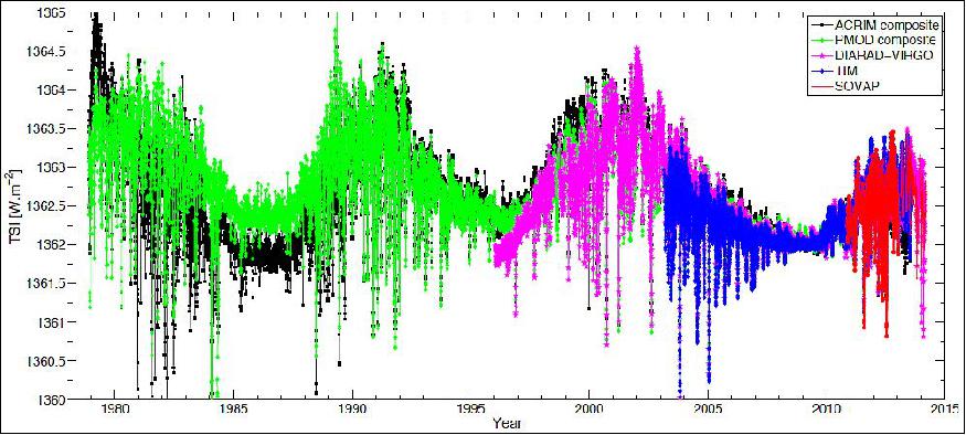
It's important to continue to measure this essential climate variable (Figure 1). The TSI is measured to vary by approximately ±0.05% (over the last three 11-year solar cycles).
Spacecraft
The SERB nanosatellite is under the scientific responsibility of LATMOS. The nanosatellite to study the radiation budget is a 3U CubeSat with a size of 10 x 10 x 33 cm, a mass of 4.5 kg and a maximum power budget of 20 W that includes the payload and the avionics.
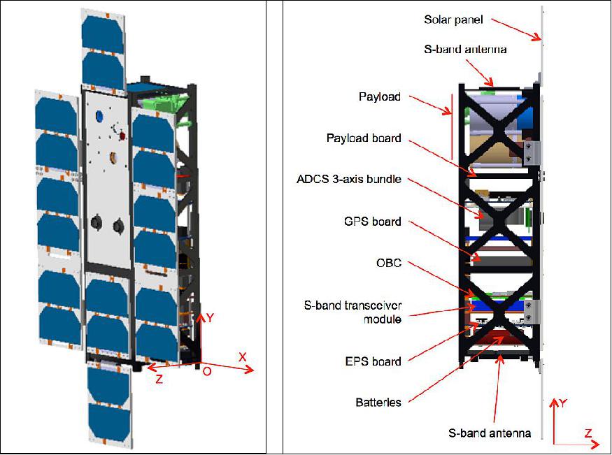
Figure 2 left shows the overall nanosatellite in a deployed configuration including the payload and the avionics. The reference frame used is also indicated. The location of the origin (O) is at the bottom of the nanosatellite. The orientation of the reference frame is as follows: +Z pointing to the Sun, +Y along the longitudinal nanosatellite axis, and +X along the deployed solar arrays. All the payload instruments have been accommodated on the nanosatellite 1U top structure.
The main elements of the SERB nanosatellite are the batteries, the EPS board, the deployable solar panels, the S-band module (~2.2 GHz), two S-band patch antennas, the OBC board, the GPS board, the ADCS 3-axis bundle, the payload board, the payload and its harness, the structure, the harness of the platform, and the thermal subsystem. All these components (Figure 2 right) will be integrated in the nanosatellite.
Volume (stowed position) | 10 (X) x 30 (Y) x 10 (Z) cm |
Volume (deployed configuration) | 30 (X) x 50 (Y) x 10 (Z) cm |
Mass | 4.5 kg (maximum with margin) |
Orbit average power generated | 18.9W (without eclipse), 15.0W (with eclipse duration ~20 minutes) |
FOV (Field of View), payload | 180º |
Data storage | 1 GB |
Downlink data rate (S-band) | 10 kbit/s to 1 Mbit/s |
Uplink data rate | 8 kbit/s to 256 kbit/s |
Ground station contact time | ~ 10 minutes per passage (~ 6 passages per day) |
Downlink volume (S-band) | ~ 400 MB/day |
Uplink volume | ~ 0.3MB/day |
Mission modes | Sun pointing, Nadir pointing, and star pointing |
Mission lifetime | One year required and three years expected |
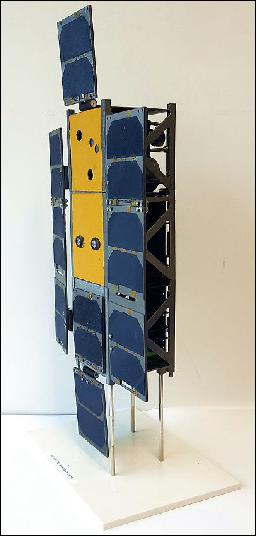
Figure 3 shows the SERB model produced with 3D printing technology. Indeed, the power of the 3D printing throughout the nanosatellite design cycle is effective for a number of reasons such as the need to have a prototype comparable to the nanosatellite, to prepare the integration and validation tests. The 3D prototype improves the communication around the project.
The mission lifetime is one year required and three years expected. For the next generation of nanosatellites, a lifetime of 11 years will be expected in order to quantify the trend between solar minima. Recording the TSI is a business in assiduity, continuity, and overlap. Uninterrupted TSI observations by temporally overlapping space-based radiometers onboard nanosatellites are essential to contiguously combine their time series into a long-term TSI record.
Pointing requirements: A minimal set of ADCS modes is defined such as the attitude and orbit control requirements for all mission phases and operational modes can be satisfied. There are three modes of active attitude control:
• Sun pointing, where the platform is three-axis stabilized. The ADCS is required to provide a pointing accuracy of ±0.2º for the Z-axis of the nanosatellite (along the payload line of sight) and a stability of 30 arcsec/s of the X and Y-axis. This level of performance is higher than the performance that is guaranteed by a standard nanosatellite platform.
• Nadir pointing, where the Z-axis of the nanosatellite is pointed towards the Earth (payload line of sight) with an accuracy better than 1º during a short period.
• Star pointing, where the Z-axis of the nanosatellite is pointed towards the stars during a short period. This is the calibration method of the instruments (reference with the deep space).
To stabilize the nanosatellite after launcher deployment, it is necessary to first detumble (process of stabilizing the angular rate of the satellite after orbital insertion) and then 3-axis stabilize the nanosatellite. Table 2 shows the inertia tensor values of the SERB nanosatellite as it would be used in the simulations to determine the main characteristics of the ADCS subsystem.
Parameter | X | Y | Z |
COG (Center of Gravity) | -50.0 x 10⁻³ | 139.4 x 10⁻³ | 56.2 x10⁻³ |
Ixx Iyy Izz | 4.68 x 10⁻² | 1.40 x10⁻² | 5.03 x 10⁻² |
Ixy Iyz Izx | 2.4 x 10⁻¹⁸ | 3.0 x 10⁻⁴ | -1. 7 x 10-18 |
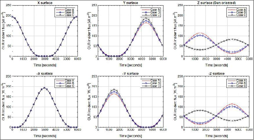
Thermal environment: The variations of the radiative fluxes (solar, OLR (Outgoing Longwave Radiation or Earth infrared flux), and albedo (or Earth reflected solar flux)) affect the temperature of the nanosatellite. Proper temperature control within the SERB nanosatellite is critical to the success of the mission. Indeed, when the temperatures change over time (orbital variations, effect of the eclipses, and long-term variations related to aging), the nanosatellite performances are impacted. Thus, the thermal design of the SERB nanosatellite requires the consideration of these effects. The boundary conditions are changing all the time, so only representative and critical situations should be studied. At least, the worst hot case [maximum power and heat fluxes at EOL (End of Life)] and the worst cold case [minimum power and heat fluxes at BOL (Beginning of Life) have to be analyzed. During eclipse period of the SERB nanosatellite (from mid-November to end of January), there are high temperature gradients in the nanosatellite at the beginning and at the end of the eclipse period that could be dangerous (thermal expansion problems). Therefore, the eclipse period is usually a worst case for the thermal control of the nanosatellite. Thus, three thermal worst cases exist:
• Case A: December solstice (with eclipse) at EOL
• Case B: hot case at the end of the eclipse period (February 1, 2022) at EOL
• Case C: cold case during June solstice at BOL.
Table 3 summarizes the main parameters of the SERB thermal worst cases. Figure 4 shows the evolution of the OLR (Outgoing Longwave Radiation) incident flux on different surfaces of the SERB nanosatellite for three thermal worst cases. A thermal balance test may be conducted to confirm the robustness of the thermal control design.
Parameter | Case A | Case B | Case C |
Solar flux (Wm-2 | 1412 | 1408 | 1324 |
OLR (Wm-2) | 237 | 237 | 237 |
Albedo | 0.35 | 0.35 | 0.27 |
Mechanical environment: The model philosophy to be adopted for the SERB mission will be in accordance with a low cost mission. The models to be produced are the electrical model and the PFM (Proto-Flight Model). For cost issues, there will be only one flight model of the SERB nanosatellite, which is called the SERB PFM. The SERB nanosatellite shall pass the mechanical tests (resonance survey, sinusoidal vibration, random vibration, shock loads, and thermal cycling in vacuum). The SERB PFM will therefore undergo environmental test to protoflight levels.
Resonance survey: The first resonant frequency shall be greater than 90 Hz (finite element model analysis and test verification). The first global mode shall be greater than 250 Hz. It is common practice to run a resonance survey test before and after running a sinusoidal or random test. By comparing the results of the resonance survey tests, a change in the nanosatellite integrity due to settling or possible damage can be found. The nanosatellite shall pass the resonance survey tests as per Table 4.
Direction | X, Y and Z |
Sweep rate | 2 octaves/minute |
Profile | 5 Hz: 0.30 g, 2000 Hz: 0.30 g |
Sinusoidal vibration: The nanosatellite shall pass the sinusoidal vibration tests as per Table 5.
Direction | X, Y and Z |
Sweep rate | 4 octaves/minute |
Profile | 5 Hz: 1.3 g, 8 Hz: 2.5 g, 100 Hz: 2.5 g |
Random vibration: The random environment applicable to the nanosatellite is indicated in Table 6, which show the PSD (Power Spectral Density) of the acceleration injected at the interface of the P-POD (Poly-Picosatellite Orbital Deployer). The system developed by Cal Poly is a standard deployment structure that ensures all CubeSat developers conform to common physical requirements.
Direction | X, Y and Z |
RMS acceleration | 8.0 g rms |
Duration | 60 s |
Profile | 20 Hz: PSD = 0.009 g2 Hz-1 |
Shock loads: A shock test shall be achieved on the SERB nanosatellite PFM model or on some qualification elements. This approach is under study. The nanosatellite will be unpowered during the test, such as in the previous tests mentioned above. Mechanical shock pulses are often analyzed in terms of shock response spectra. The shock response spectrum assumes that the shock pulse is applied as a common base input to an array of independent single-degree-of-freedom systems. The shock response spectrum gives the peak response of each system with respect to the natural frequency. Damping is typically fixed at a constant value, such as 5%, which is equivalent to an amplification factor of Q equal to 10. Levels of shock test (in each of the three axis) are specified in Table 7.
Direction | X, Y and Z |
Q-factor | 10 |
Number of shocks | 2 |
Profile | 30 Hz: 5 g |
Thermal cycling in vacuum: Thermal cycling in vacuum is conducted to determine the ability of the nanosatellite to withstand mechanical stresses induced by alternating high and low-temperature extremes. Permanent changes in electrical and/or physical characteristics can result from these mechanical stresses. Levels of thermal cycling for the payload are specified in Table 8. The payload will be operational during the test.
Maximum non-operational | 60ºC |
Maximum operational | 50ºC |
Minimum operational | -35ºC |
Minimum Switch-On | -35ºC |
Minimum non-operational | -45ºC |
Number of cycles, Dwell time | 4, 3 hours |
Rate of Change | >2ºC per minute |
Pressure | < 10-5 mbar |
Nanosatellite structure: The structure will be carried out with aluminum. Stainless steel tie-rods will be used to support all electronic boards of the SERB nanosatellite. Moreover, all materials (aluminum alloy (6082-T6) and AA7075 T7351 aluminum for the structure, steel screw for all the fasteners, polyimide (PI) printed circuit board, etc.) and coating selection (black paint, white paint, alodine, black anodization, etc.), must be compliant with specific requirements such as TML (Total Mass Loss) less than 1% and CVCM (Collected Volatile Condensable Material) less than 0.1%, according to guidelines for spacecraft cleanliness control. A cleanliness program will be implemented to control molecular and particle contamination of the nanosatellite.
EPS (Electrical Power Subsystem): The SERB nanosatellite requires a power subsystem that will generate, condition, monitor, manage, and distribute power amongst the individual subsystems. The power subsystem will consist of three main elements, the batteries, the EPS board that is a power control and a monitoring board, and the deployable solar panels with its solar cells.
Use of VES16 batteries that are specially adapted for space applications. Main typical performances of the Saft VES16 battery are a nominal capacity of 4.5 Ah, a mean voltage of 3.6 V, and an energy around 16 Wh. An alternative is to use the 3G Clyde Space CubeSat Battery (30 Whr Battery), which is under study.
The Clyde Space EPS board (3G FlexU EPS with the reference 01-02453) will be used. The Clyde Space EPS can accommodate various solar panel configurations and has been designed to be versatile. The main features include:
- 3.3 V, 5 V, and 12V regulated power buses
- Unregulated battery bus
- 10 LCL (Latch-up Current Limiter) power distribution modules
- MPPT (Maximum Power-Point Tracking) battery charge regulators
- Over-current, over and under-voltage protection
- Watchdog timer
- USB battery charger for ground testing
- And a separation switch.
Solar cells: The nanosatellite will use 18 solar cells on the +Z surface of the nanosatellite and 4 solar cells elsewhere. The 30% triple junction GaAs solar cells (TJ Solar Cell 3G30C) from Azur Space will be used. During the solar pointing mode (June solstice), the average power generated is ~19W (Table 9), which is much greater than the nanosatellite power consumption (13.8 W for case EPC1). The SERB nanosatellite is on a SSO orbit at an altitude of 680 km, allowing continuous observations of the Sun, except for short periods during a November-January \eclipse season" when the Earth comes within the nanosatellite payload line-of-sight once per orbit. During this period, the orbit average power generated is close to 15 W (eclipse duration ~20 minutes). In order to show than the power budget is sustainable, an initial depth of discharge (DoD) of the batteries of 20% is assumed and it can be seen that at the start of the next orbit, the DoD is recovered to less than 20%, meaning a minimum power budget. Therefore, the minimum power generated by the nanosatellite during the \eclipse season" is close to 12.0 W, which is only compliant with the nanosatellite power consumption in case EPC2 (Table 1).
Solar cell area | 30.18 cm2 |
Number of solar cells on +Z surface | 18 |
Cell efficiency | ~0.28 |
EPS efficiency | ~0.9 |
Incident power | 75.2 W |
Minimum power generated | 18.9 W |
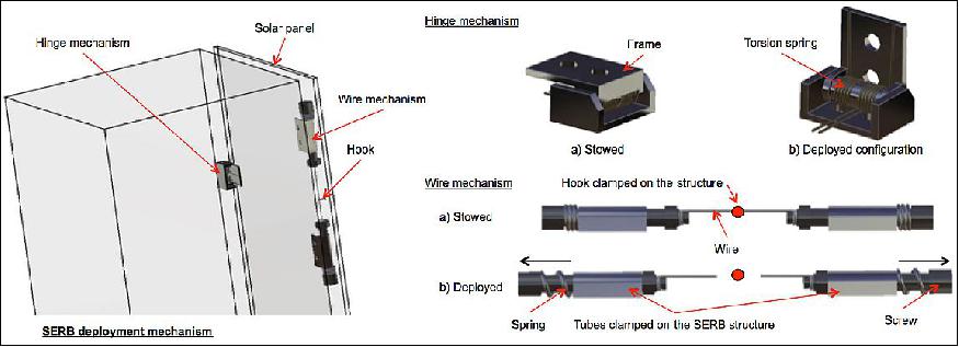
Deployable system: The deployable system (Figure 5) is a crucial part in order to open the solar panel and receive enough energy from the Sun to power supply all the components of the SERB nanosatellite. The deployable system is outside of the structure and must survive to the harsh space environment. The goal of the following deployable system is to create an innovative system that can be used on any CubeSat with high cleanliness requirements. The deployable system, shown on the left of Figure 5, can be split into three subsystems that are the solar panel, the wire mechanism with its hook, and the hinge mechanism. The wire mechanism keep the solar panel closed during takeoff while the hinge mechanism open the solar panel during the deployment in space.
S-band module and S-band patch antennas: The EWC31 S-band transceiver module for nanosatellite (Syrlinks, France) will be used. For the TM, the equipment operates in the 2200-2290 MHz range. The RF output power can be adjusted from +27 to +33 dBm (at duplexer output) with data rates from 10 kbit/s to 1 Mbit/s. For the TC, the equipment operates in the 2025-2110 MHz frequency range at a data rate, which can be selected from 8 kbit/s to 256 kbit/s. The nominal power consumption (TC) is close to 1.2 W typical. The power consumption (TM and TC) is less than 12 W for +33 dBm RF output power that represents no more than 15% during an orbit (link with the ground-based S-band antenna).
OBC (On-Board Computer): The SERB nanosatellite has an onboard computer to manage all systems. The NINANO (Numeric Intensive Node for Applications mono-module adaptation for nanosatellites) OBC will be provided by Steel Electronique, which is a French company specialized in the design of space electronic unit. The OBC will be the same as that used on the EyeSat nanosatellite (JANUS) project). The main Steel Electronique OBC internal features are: 1 GB DDR3 (Double Data Rate type three), 8 kB FRAM (Ferroelectric Random-Access Memory), 16 MB QSPI (Quad-Serial Peripheral Interface) flash for boot loader and programmable logic (PL) configuration, 8 Gbit NAND (Negative- AND) flash for data storage (PS) or 128 Gbit if handled by PL, and 33.33 MHz ultra-stable Crystal Oscillator (XO). Indeed, the ultra-stable crystal oscillator is required to have a knowledge of the time acquisition with a high accuracy.
GPS receiver: The project uses the GPS electronic board and the antenna of SSTL (Surrey Satellite Technology Ltd.) to process the positioning and timing information. The main typical performance of the SSTL Space GPS Receiver (SGR-05U) is a knowledge of the nanosatellite position at 10 m (at 95% confidence levels). The knowledge of the satellite position is required to determine the SERB-Sun distance (z) and to achieve a radiation budget of the Earth with high accuracy. In addition, the SSTL antenna (mass of 12 g with 13 x 13 x40 mm size) will be used.
ADCS (Attitude Determination and Control Subsystem): The 3-axis ADCS is developed by the Electronic Systems Laboratory of Stellenbosch University (South Africa). The unit consists of three subsystems integrated into a compact bundle. The first module is a sensor module that interfaces with two magnetometers (one deployable and one redundant) and ten coarse solar sensors mounted on each face of the nanosatellite. The second module is a Sun and a nadir sensor that uses two cameras with a 160º FOV. The third module is a generic CubeSat on-board computer and the last module is composed of three reaction wheels magnetically shielded and mountable in three axis. This bundle should be able to match the precision requirements of the nanosatellite, and to stay within reasonable mass and power budget.
Launch
A launch of SERB is planned for 2020.
Orbit: Sun-synchronous dawn-dusk orbit, altitude of 680 ±30 km, inclination of 98.8±0.2º, LTAN (Local Time on Ascending Node) at 6:00 ±0.30 hr.
Sensor Complement
The sensor complement consists of four instruments are accommodated in a 1U volume.
SR (Solar Radiometer)
SR features a new instrument design used with VACNT (Vertically Aligned Carbon Nanotube) for the measurement of the TSI (Total Solar Irradiance). It covers the spectral range from 0.1 - 3 µm, with a mass of 0.32 kg, and with the dimensions of 47 mm diameter by 95 mm length.
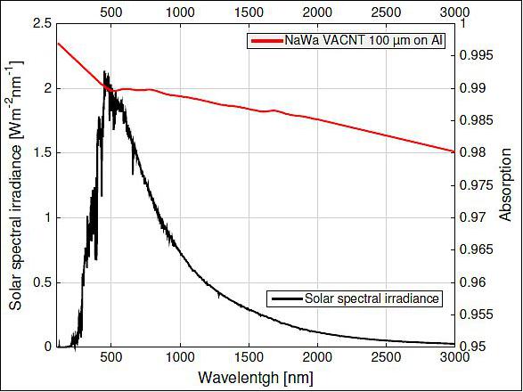
The efficiency of the solar radiometer detector depends on the coating used. The VACNT technology is used for this application. Figure 7 shows the solar absorption of the NaWa technologies (France) VACNT of 100 µm on aluminum. The thicker the VACNT layer, the better is the absorption. Ground tests will be required to validate the process.
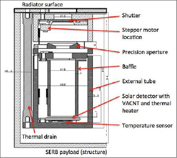
The main features of the solar radiometer include:
- A solar detector with VACNT, its thermal heater (H1), its temperature sensor, and its heat sensor flux
- A baffle with VACNT to absorb the solar flux reflected by the solar detector
- A precision aperture with its mirror-holding device to minimize the thermomechanical stresses
- A shutter to open and close the cavity with a sampling period of 120 s (60 s open and 60 s closed)
- A stepper motor that opens the shutter
- An external tube with its thermal heater (H2) and its temperature sensor
- A thermal drain to link the external tube and the radiator surface
- And a thermal radiator with its cold coating.
Active thermal control system of the solar radiometer includes a thermostatically controlled resistive electric heater (H1) to keep the solar detector at a temperature of 35ºC, and another electric heater (H2) to keep the external tube at a temperature of 20ºC. The first step is to stabilize the temperature of the external tube. For this, a PI (Proportional Integral) loop is used to control the temperature of the external tube of the solar radiometer. Then, the solar detector is thermally controlled by a fast bang-bang modulation.
Thermal Analysis of the Solar Radiometer
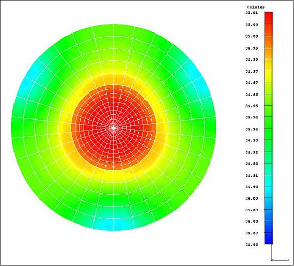
Steady state cases: A thermal model was developed to study the temperatures of the solar radiometer in two cases: a hot and a cold case (rules of the design). There is a radiative exchange between the radiator surface and the deep space, which is assumed as a blackbody at 3 K. The external surface of the radiator has a second surface mirror coating (emissivity of 0.75 in the far-infrared range and solar absorption of 0.11 in BOL and 0.17 in EOL), which absorbs solar flux, Earth infrared flux, and Earth reflected solar flux. To avoid thermal radiation with the payload at a temperature Tp, the external tube of the solar radiometer is covered with a MLI blanket. Table 10 and Table 11 summarize the main results of this analysis. Figure 8 shows the temperatures distribution of the solar detector (case A-c). With this system, a very accurate thermal control of the solar detector is obtained by using the two thermal heaters of the solar radiometer. The mean power consumption of the thermal control of the solar radiometer is close to 1.9 W without margin (worst cold case).
Case A | a | b | c |
Solar detector | 16.67ºC | 28.12ºC | 35.00ºC |
Baffle | 5.63ºC | 16.98ºC | 18.12ºC |
External Tube | 7.87ºC | 20.00ºC | 20.00ºC |
Radiator | 7.42ºC | 16.37ºC | 16.38ºC |
Heater H1 | - | - | 0.093 W |
Case C | a | b | c |
Solar detector | -20.34ºC | 27.57ºC | 35.00ºC |
Baffle | -30.95ºC | 16.47ºC | 17.74ºC |
External Tube | -29.82ºC | 20.00ºC | 20.00ºC |
Radiator | -30.35ºC | 8.64ºC | 8.63ºC |
Heater H1 | - | - | 0.103 W |
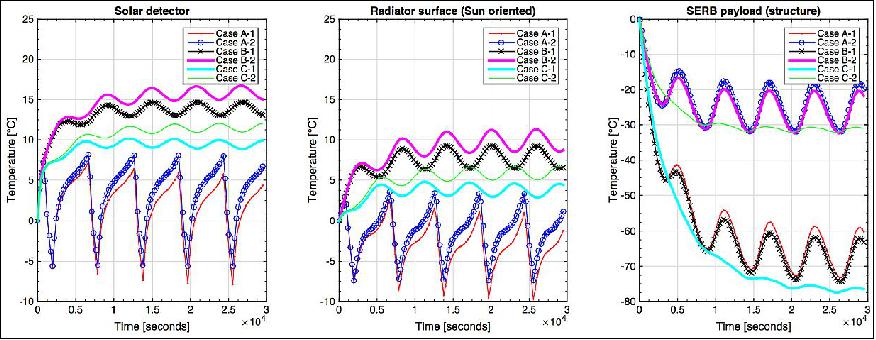
Transient cases: Figure 9 shows the temperatures evolutions in six cases as described below:
- Case A-1: December solstice without dissipation
- Case A-2: December solstice with dissipation (Pp)
- Case B-1: hot case without dissipation
- Case B-2: hot case with dissipation (Pp)
- Case C-1: cold case without dissipation
- Case C-2: cold case with dissipation (Pp).
There is no active thermal control for the solar detector and the external tube. Indeed, the thermal heaters (H1 and H2) are switched off, that help to understand the temperature margins of the solar radiometer definition. These results clearly show that the solar detector could be thermally controlled at a temperature of 35ºC during the mission lifetime according to the different incident fluxes. There is a temperature margin of more than 15ºC.
Stepper motor | Faulhaber AM1020, V12-250, 250 Ω per phase, 0.045 A per phase |
Temperature sensors | AD590MF, 10-4 ºC resolution |
Heater H1 (option 1) | Vishay EA-XX-500JD, 12.7 mm of diameter, 0.5 W maximum power, 120Ω, On-off thermal control, PWM, 10 ms cycle |
Heater H2 | MINCO 5562R38, 33.5 mm of diameter, 3.8W maximum power, 38 Ω, PI control algorithm, PWM, 100 ms cycle |
TSI sensor with H1 (option 2) | CAPTEC: 1 cm2, 0.25 µV/(Wm-2), Heater H1 (165 mW) |
Legend to Table 12: PWM (Pulse Width Modulation)
ER1 and ER2 (Earth Radiometers 1 and 2)
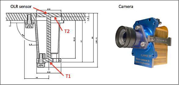
Two Earth radiometers (ER1 and ER2) are simple systems (Figure 10, left) with the objective is to measure the OLR (Outgoing Longwave Radiation and Earth reflected solar flux (albedo)). The instruments have a mass of 0.03 kg each, covering 0.2 to 100 µm spectral range and with the maximum dimensions of 22 x 22 x 22 mm. The power consumption of the Earth radiometers will be close to 0.1 W (from temperature sensors T1 and T2 of the radiometers). This simple design is under study. The objective is the measure the infrared radiation and the albedo.
Camera
The objective of the camera is to take pictures of the Earth. The camera will use a CCD (Charge Coupled Device) detector with its optic, which represents the SERB camera (Systheia, France) as shown in Figure 10 (right). The SERB camera objective is to take images of the Earth in the visible or in the near-infrared spectra. The main features are:
- A volume of 53 x36 x 66 mm3
- A mass of 0.13 kg (with margin)
- A power consumption of 1.9W (with margin)
- A 1 Mpixel CCD detector (1024 x 1024) with a pixel size of 14 µm
- A ground sample distance of 0.425 km
- A focal length of 22.4 mm
- A FOV of 36.7º.
SP (Solar Photometer)
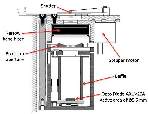
The objective of the SP is to measure the solar radiation Herzberg continuum between 200 and 242 nm. The solar photometer of new instrumental design (Figure 11) will be used for the SSI (Solar Spectral Irradiance) measurement at 215 nm by using an interferential filter (ANDOVER or ACTON products), an electron detection (AXUV20A from OPTO DIODE Corp.), and a stepper motor of size 8 (model AEM 08-940 from THALES, France). The maximum mass of the solar photometer is close to 0.36 kg and with the dimensions of 50 mm diameter by 95 mm length. The power consumption of the solar photometer will be close to 0.5 W (stepper motor and electron detection). The design of the solar photometer is under study.
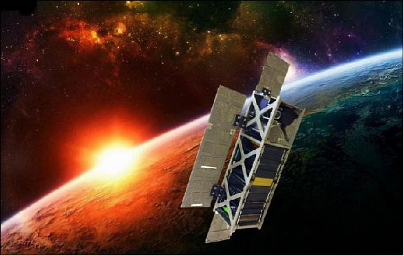
In summary, the SERB nanosatellite (Figure 12) aims three scientific objectives in connection with the observations of the Earth and the Sun. The technologies developed for this innovative proof-of-concept nanosatellite are affordable and workable on the same small platform (10 x 30 x 50 cm in a deployed configuration), which is suitable for a constellation of satellites and an overlap in order to realize long-term spaceborne measurements. The architecture is well organized through the three units of the nanosatellite. The deployable system of the solar panels designed for this nanosatellite is proper for any CubeSat and cleaner than classic systems.
The power budget of the SERB sensor complement highlights that all instruments cannot operate simultaneously during the eclipse period. Thus, the SERB camera will be used occasionally to take pictures of the Earth.
References
1) Mustapha Meftah, Philippe Keckhut, Alain Hauchecorne, Abdanour Irbah, "SERB, a nanosatellite dedicated to Sun-Earth relationship," 4th Interplanetary CubeSat Workshop South Kensington, London, United Kingdom, 26-27 May 2015, URL of abstract: http://icubesat.org/papers/2015-2/2015-a-3-3/ URL of presentation: https://icubesat.files.wordpress.com/2015
/06/icubesat-2015_org_a-3-3_serb_meftah.pdf
2) Mustapha Meftah, Étienne Bamas, Pierre Cambournac, Philippe Cherabier, Romain Demarets, Gaspard Denis, Axel Dion, Raphaël Duroselle, Florence Duveiller, Laetitia Eichner, Dimitri Lozeve, Guillaume Mestdagh, Antoine Ogier , Romane Oliverio, Thibault Receveur , Camille Souchet, Pierre Gilbert, Germain Poiet, Alain Hauchecorn, Philippe Keckhut, Alain Sarkissian, "Proceedings of SPIE, Vol. 9838, 'Sensors and Systems for Space Applications IX,' 98380T, Baltimore, MD, USA, April 17, 2016, doi:10.1117/12.2222660
3) M. Meftah, M. Brand, L. Wauquiez, G. Poiet, A. Sarkissian, A. Hauchecorne, P. Keckhut, "SERB, a nanosatellite dedicated to observe the Sun and the Earth," Proceedings of the 67th IAC (International Astronautical Congress), Guadalajara, Mexico, Sept. 26-30, 2016, paper: IAC{16{A3.5.8
The information compiled and edited in this article was provided by Herbert J. Kramer from his documentation of: "Observation of the Earth and Its Environment: Survey of Missions and Sensors" (Springer Verlag) as well as many other sources after the publication of the 4th edition in 2002. - Comments and corrections to this article are always welcome for further updates (eoportal@symbios.space).
Overview Spacecraft Launch Sensor Complement References Back to top