Shuttle Flight STS-85
EO
NASA
Mission complete
Quick facts
Overview
| Mission type | EO |
| Agency | NASA |
| Mission status | Mission complete |
| Launch date | 07 Aug 1997 |
| End of life date | 19 Aug 1997 |
| CEOS EO Handbook | See Shuttle Flight STS-85 summary |
Shuttle Flight STS-85 - Overview of the EO payload complement
STS-85 (Shuttle Discovery, Aug. 7-19, 1997) carried a complement of payloads in the cargo bay that focused on MTPE (Mission to Planet Earth) objectives as well as preparations for International Space Station (ISS) assembly. Overall, STS-85 was one of the most complex Shuttle missions flown by NASA. The payload mass of STS-85 was about 11,200 kg. Note: There were additional payloads aboard beside those described here.
Orbit
average altitude of 320 km, inclination of 51.6º, a total of 185 orbits were flown in 11 days and 19 hours.
Spacecraft
The major payload modules in the cargo bay were: 1) 2)
1) CRISTA-SPAS-2 (Cryogenic Infrared Spectrometers and Telescopes for the Atmosphere - Shuttle Pallet Satellite-2) The CRISTA-SPAS-2 platform was deployed during the Shuttle mission (deployment on Aug. 7. and retrieval on Aug. 16). There were three payloads on the SPAS platform: CRISTA, MAHRSI and IPEX-II.
2) TAS-01 (Technology Applications and Science-01)
3) MFD (Manipulator Flight Development) of JAXA (formerly NASDA), Japan. MFD was designed to evaluate the operation of the SFA (Small Fine Arm), intended to be used in the future RMS (Remote Manipulator System) of JEM (Japanese Experiment Module) on ISS. SFA was mounted on top of MPESS (Multi-Purpose Experiment Support Structure).
4) IEH-02 (International Extreme Ultraviolet Hitchhiker-02), a reflight of IEH-01 on STS-69 (Sept. 7-18, 1995). The objective was to study the solar extreme ultraviolet (EUV) flux and EUV emissions of the Jupiter Io plasma torus system. IEH-02 consisted of four experiments: 3)
5) SEH-2 (Solar Extreme Ultraviolet Hitchhiker-2) of USC (University of Southern California). The SEH-2 experiment is is designed to accurately measure the solar flux in the EUV region of the solar spectrum. The EUV radiation is especially important in atmospheric studies since these wavelengths interact directly with atmosphere components, and form the planetary ionosphere. SEH-1 was flown on the STS-69 mission.
6) UVSTAR (Ultraviolet Spectrography Telescope for Astronomical Research) of NASA and ASI. UVSTAR, of STS-69 mission heritage, is a joint collaboration between the Universities of Arizona and Trieste, Italy. The objective was to study extended sources of EUV bands. The UVSTAR instrumentation provided Jovian system EUV data.
7) DATA-CHASER (Distribution and Automation Technology Advancement - Colorado Hitchhiker and Student Experiment of Solar Radiation) of the University of Colorado. The objective is to demonstrate distributed, interactive and intelligent control approaches that enable space payloads to be operated by scientists from their home institutions. The DATA canister represents the advanced technology goals, and the CHASER canister represents the scientific goals.
8) GLO-5 and GLO-6 (Glow Experiment-5 and Glow Experiment-6), two separate scan platforms of the University of Arizona. The objective is to measure Earth's atmospheric emissions, day and night glow, and aurora. The platforms allow stereoscopic measurements of the size and range of structures. The GLO experiments are also being used to study the Shuttle glow phenomena in the 115 - 1,150 nautical mile range.
CRISTA-SPAS-2 Free Flyer Platform
The prime payload of the mission was CRISTA-SPAS-2 (Cryogenic Infrared Speedometers and Telescopes for the Atmosphere-Shuttle Pallet Satellite-2), a joint venture of DLR (German Space Agency) and NASA, and a reflight of the CRISTA-SPAS-1 mission on the generic ASTRO-SPAS platform on the ATLAS-3 mission (STS-66, Nov. 3-14, 1994). The small free-flying satellite contained three telescopes and four spectrometers (see CRISTA-SPAS-1 in ATLAS description).
The SPAS carrier is battery-powered which stored its data onto tapes for post-flight analysis. A major advance was made in the performance of the ASTRO-SPAS platform. The attitude of the satellite is derived from a star field camera and a gyro package in combination with a GPS (global positioning system) position determination. The attitude is actively controlled via a cold-gas system. For the second CRISTA mission a new attitude control software was available; this allowed the satellite to be slewed around the local vertical axis, while maintaining the fields of view of all three telescopes at the Earth's limb. The attitude timeline could be changed by ground commands in near real time. This capability facilitated a number of observational modes which considerably enhanced the science return from this mission, including the extension of the latitudinal coverage to ±74º. 4)
The primary experiment was the CRISTA, a system of three telescopes and four spectrometers to measure infrared radiation emitted by the Earth's middle atmosphere. A complementary instrument called MAHRSI (Middle Atmosphere High Resolution Spectrograph Investigation) was also carried on the payload together with a passive experiment called SESAM (Surface Effects Sample Monitor). MAHRSI measured ultraviolet radiation emitted and scattered by the Earth's atmosphere.
Two additional experiments were mounted on the SPAS and were activated during free-flight. The Mini Dual Earth Sensor (MiDES) was used to gather operational data of the Earth horizon positions, and the IPEX-II (Interferometry Program Experiment-II) to measure the vibration of the SPAS structure.
Note: The CRISTA payload itself is described under “ATLAS payloads” on the eoPortal.
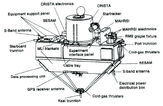
The CRISTA-SPAS-2 payload was deployed on flight day one, to gather data about Earth's middle atmosphere. After more than 200 hours of free flight, CRISTA-SPAS-2 was retrieved on Aug. 16, 1997. The three CRISTA telescopes collected 38 full atmospheric profiles of the middle atmosphere. A total of 22 sounding rockets and 40 balloons were launched to provide correlating data in the ground segment.
The scientific emphasis was on the study of small-scale tracer “filaments” (long, thin regions of differing composition, including temperatures) in the stratosphere. Data analysis of the two CRISTA-SPAS missions may indicate, how these filaments contribute to the transport of ozone. The STS-85 flight offered an opportunity for increased latitudinal coverage of the atmosphere beyond that of the STS-66 mission (data of summer conditions at northern latitudes and the polar night at high southern latitudes). A CRISTA/MAHRSI campaign, employing balloons, research aircraft, etc. was conducted in Europe in parallel to the STS-85 mission, in support of CRISTA-SPAS-2 observations.
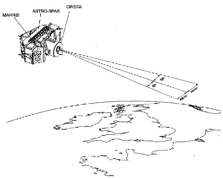
MAHRSI (Middle Atmospheric High Resolution Spectrograph Investigation)
From NRL (Naval Research Laboratory), PI: R. Conway. Same instrument as in the ATLAS-3 mission on STS-66 (CRISTA-SPAS-1). MAHRSI was mounted on the ASTRO-SPAS free-flyer platform. During the STS-85 flight, MAHRSI gathered new vertical profile data on the distribution of OH in the mesosphere and upper stratosphere under very different conditions (both seasonal and diurnal) from its previous flight on STS-66. Also, more measurements of nitric oxide were conducted. Researchers hope to gain a better understanding of how hydroxyl (OH) behaves during different seasons around the globe and how it interacts with the behavior of ozone and other trace gases.
MAHRSI is a high spectral resolution (0.018 nm) imaging spectrometer sensitive in the wavelength region from 190 nm to 320 nm. MAHRSI's primary objective is to measure limb intensity profiles of the resonance fluorescent scattering of sunlight by hydroxyl (OH) in the altitude region from 38 to 90 km, and by Nitric Oxide (NO) in the region from 48 to 160 km. From these intensity profiles, global vertical density profiles of OH and NO with a vertical resolution of 2 km and a down-track resolution of 8º - 12º are inferred. By measuring Rayleigh scattering intensity profiles, the experiment also provides precise knowledge of the neutral density and temperature in the mesosphere. 5) 6) 7) 8)
MAHRSI was coaligned with the CRISTA experiment and scanned on the limb from 160 to 48 km with a scan time of between 72 and 202 seconds. NO densities were inferred as a function of altitude from these scans with an algorithm that includes self-absorption and that is constrained by the smoothness of the profile. Some of these limb scans measured the same geographic locations on sequential orbits and thus provided observations separated by 90 minutes of local time. These measurements occurred at low latitudes, low geomagnetic activity, and low solar activity.
IPEX-II (Interferometry Program Experiment-II)
A NASA/JPL experiment mounted on the ASTRO-SPAS free-flyer platform. The prime objective was to monitor on-orbit the microdynamic behavior of space-like booms (to serve as input for future interferometry missions - such as SRTM). The IPEX-II boom is a 9-bay expandable ADAM mast (2.35 m x 0. 3 m x 0.3 m), developed by AEC-Able, with steel-bracing cables pre-loaded at about 112 kg. The boom was cantilevered to the side of the ASTRO-SPAS platform. The truss was instrumented with 22 accelerometers (16 on the truss and six in the interface struts), six load cells (in the interface struts), thermistors, and two proof-mass actuators located at the truss free end for conducting on-orbit system identification. The experiment consisted of three phases: 9) 10) 11) 12) 13)
• Investigation of thermal snapping in joint-dominated structures due to temperature gradients. A suite of 24 high sensitivity micro-g accelerometers with collocated temperatures sensors, mounted on the boom, monitored normal operations aboard CRISTA-SPAS in free flight. Data was obtained for five sun-to-shade orbital periods.
• Investigation of structural boom behavior due to induced loads. Two shakers, mounted orthogonally at boom tip, performed random and step-sine tests between 9-300 Hz, with loads from 0.048 to 0.00055 kg to detect any possible nonlinear behavior in the boom.
• Investigation to isolate and to quantify on-board disturbance sources of the CRISTA-SPAS platform and to measure their effect on the boom. This involved gyro and thruster operations and in-between times.
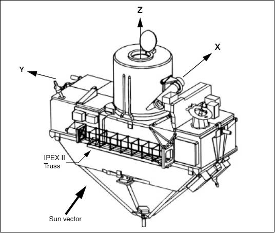
One of the interesting results from the IPEX-II flight experiment was the observation of spontaneous dynamic responses near a transition from nighttime to daytime. These microdynamic thermal snaps were apparently correlated with the temperature rise on the structure. But unlike previous experiences with such thermal snaps, these vibrations had extremely low amplitudes, on the order of micrometers or less. 14) 15)
To correspond with the CRISTA/SPAS mission, researchers from all over the world participated in the CRISTA/MAHRSI Campaign 2. This three-week cooperative science campaign included the collection of complementary and correlative measurements from ground-based stations, balloons, rockets, aircraft and satellites. These measurements became part of a database to be used to validate the CRISTA and MAHRSI observations.
Once the science operations were complete, the CRISTA-SPAS-2 free-flyer platform was used in simulation exercises to prepare for the first ISS (International Space Station) assembly flight, namely STS-88 (Dec. 4-15, 1988), with the payload being manipulated as if it were the Functional Cargo Block (FGB) - to be attached to ISS Node 1.
TAS-01 (Technology Applications and Science-01) Payload
TAS-1 was a Hitchhiker (HH) payload on STS-85 carrying various experiments designed to demonstrate faster, better, cheaper avionics and processes (standardized Hitchhiker avionics to provide power and enables command and transmission of experiment data to and from the payload). The HH payloads were carried in the Shuttle bay on two cross-bay Hitchhiker bridge assemblies. TAS-01 consisted of the following payloads:
• ISIR (Infrared Spectral Imaging Radiometer)
• SLA (Shuttle Laser Altimeter)
• SOLCON (Solar Constant Experiment)
• CVX-1 (Critical Viscosity of Xenon)
• CFE (Cryogenic on-orbit long life active refrigerator Flight Experiment) of the USAF Phillips Laboratory. The objective of the experiment is to test the operation of an engineering development model of a cryogenic cooler. The focus is on demonstrating the collection and distribution of oil used to lubricate the long-life Joule-Thomson (J-T) compressor, and the collection, storage, and application of liquid nitrogen to provide uniform and precise temperature control of the components that have varying heat loads (two stages of cooling at 65 K and 120 K). Long-term cryogenic cooling is a technology that may be used on future space missions to cool superconducting computers and sensors or to extend the capabilities of life support systems.
• TPF (Two Phase Flow) of NASA/GSFC. The objective is to demonstrate and characterize flight operation of a capillary pumped loop (CPL) experiment with advanced features and components. TPF was mounted on top of MPESS (Multi-Purpose Experiment Support Structure).
• SEM (Space Experiment Module) of NASA/GSFC. SEM-02 is a canister also mounted on top of the MPESS that contains 10 separate modules, each containing a separate experiment designed and constructed by students. This payload is part of a NASA initiative to increase educational access to space.
• SAAMD (Stand Alone Acceleration Measurement Device) of NASA. SAAMD is a self-contained autonomous data acquisition system designed to measure low frequency acceleration in the Space Shuttle during launch and landing. The device is triggered by an inertia switch that is closed by the vibration of starting the main engines prior to launch and is triggered again by an inertia switch closed upon reentry.
• WBSAAMD (Wide Band Stand Alone Acceleration Measurement Device) of NASA. WBSAAMD measures acceleration at a higher frequency range.
ISIR (Infrared Spectral Imaging Radiometer)
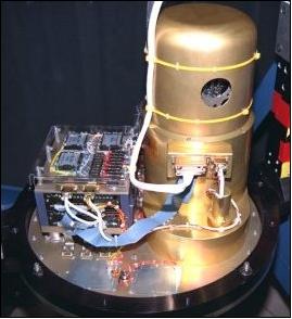
ISIR is a high-precision, multispectral imaging radiometer of NASA/GSFC (built by Space Instruments Inc., Encinitas, CA). The objective of ISIR was to demonstrate/validate a new infrared imaging technology with an uncooled detector array for the measurement of the infrared brightness temperature of cloud tops as well as the Earth's surface. The new technology is based on microbolometer focal plane arrays, allowing infrared imaging without external cooling. The ISIR detector is a warm focal plane 327 x 240 pixel array of silicon micromachined microbolometers. ISIR demonstrated the potential of this new technology for future much more compact, lower cost and more reliable spaceborne infrared imagers. On STS-85, ISIR was operated in conjunction with the Shuttle Laser Altimeter (SLA-2), for a new type of cloud science observation through combined active and passive remote sensing.
ISIR is a compact spectral imager providing radiometrically calibrated infrared imagery in three narrow spectral band centers at 8.55, 10.8 and 11.8m, and in a broad-band window from 7 to 13 µm. ISIR's main scientific mission is to image clouds from Shuttle orbit and provide information on cloud-top temperature and classification. A science goal is discrimination of cirrus cloud particle type by split-window analysis. The split-window analysis involves the differential radiance between the 10.8 and 11.8 µm atmospheric window channels. The required NEDT (Noise Equivalent Difference Temperature) system sensitivity performance was 0.1 K. The target spatial resolution was 250 m with a total image swath-width of 85 km from the shuttle altitude.
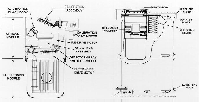
ISIR is a pushbroom imager with an MBA (Microbolometer Array) detector. A scene is imaged in a fixed staring mode with the cross-track pixels providing the image swath. Imaging is done with a f/0.73 germanium lens of 50.8 mm focal length and 70 mm optical diameter. The cross track full FOV is approximately 15º. A filter wheel between the lens and detector array is driven for spectral selection. In order to obtain the necessary instrument calibration during operation, an on-board blackbody calibration target is included. The blackbody is viewed by swinging in a mirror in front of the lens. A curved focussing mirror is used in order to minimize the size of the blackbody target. The overall instrument includes electronics and tape recorders. Two standard Exabyte-8505c 8mm tape recorders were used for data storage. 16) 17) 18)
Spectral bands (4) | 8.2 - 9.0 µm; 10.3 - 11.3 µm; 11.5 - 12.5 µm; and 7.0 - 13 µm |
Dynamic range | Scene temperatures from 0 K to 400 K |
NEDT @ 300 K | 0.01 K to 0.06 K (required performance was 0.1 K) |
Spatial resolution | 1 mrad (250 m on ground from Shuttle @ 250 km) |
Field of View (FOV) | 19.25º. (81 km swath on ground from shuttle @ 250 km) |
Optics | f/0.73, 50 mm focal length, 68 mm diameter |
Inflight calibration | Ambient & cold calibration capability |
Instrument mass; power | 13 kg; 20 W operating, 120 W during cold calibration |
Instrument size | 45 cm x 35 cm x 30 cm |
Data rate | 368 kbit/s (with 12 bit encoding) |
Cryogenic cooling of detectors | None |
The primary advantage of the MBA detector (built by Loral with DARPA funding) used in ISIR is that it is a large-format (327 x 240) array providing good sensitivity in the thermal IR at room temperature. A TDI (Time Delay Integration) operating mode was implemented providing a (x 40) cumulative imaging capability. This required a special flight operation mode for high resolution imaging with less than 1/8 pixel smearing. An instrument roll stability of 0.01º/s and a yaw accuracy to the ground velocity vector of ±0.1º were provided by the Shuttle.
A complementary instrument to ISIR was SLA. Both instruments permitted to combine thermal IR observations and laser ranging for cloud remote sensing. 19)
During the STS-85 mission, three special surface tracking maneuvers were executed by the Shuttle for the ISIR experiment. The goal was to image the thermal emission of cloud tops in high resolution over a large range in angles. The results permit test of angular cloud radiation models that are a key element for cloud retrieval applications of current GOES and LEO satellite data. - There were three aspects of the ISIR experiment that were firsts from space for cloud science.
• The combination with direct laser measurements of cloud height
• A global data set of thermal infrared imagery at near ¼ km resolution was acquired
• The additional new observation from space was the use of the 8.5 µm wavelength, which has applications for cloud particle discrimination.
Naturally, the warm focal detectors were individually not as sensitive as a performance attainable with cooled detectors. The primary design issue for ISIR was whether it would be possible with signal integration to take advantage of the throughput potential of the approximately 80,000 detectors in the array for practical space imagery.
SLA (Shuttle Laser Altimeter)
The SLA sensor package is a NASA/GSFC designed and developed instrument within the MTPE program, a pathfinder for future operational spaceborne laser remote sensing devices and lidar over land surfaces, which was flown as a `hitchhiker payload' on two Shuttle flights.
1) The first flight (SLA-1) took place on STS-72 (January 11-20, 1996). The orbit had an inclination of 28.5º.
2) The second flight, SLA-2, was on STS-85 (Aug. 7-19, 1997) with an obit inclination of 51.6º.
SLA has three major objectives:
• To provide an in-space engineering testbed for future spaceborne laser altimeters
• To acquire samples of land topography and vegetation data
• To measure cloud and aerosol layers in the atmosphere
The first and second flights of SLA characterized ocean, land and cloud top elevation and vertical roughness in 100 m diameter laser footprints spaced every 700 m along a nadir profile.
SLA-1 on STS-72
The SLA instrument package consisted of the LAC (Laser Altimeter Canister) and ASC (Altimeter Support Cannister) which were interconnected. The LAC is equipped with an opening motorized door assembly with an optical window. LAC contains a laser transmitter and a concave mirror/detector which collects the reflected laser radiation. The ASC contains control, telemetry, telecommand and power conditioning electronics. 20)
The SLA instrument consists of a 38 cm telescope, a diode-pumped Nd:YAG laser transmitter (Q-switched), an altimeter receiver electronics package, and a 250 MHz waveform digitizer coupled to the altimeter receiver for capturing the backscattered echoes from the interaction of short duration laser pulses (~ 8 ns duration) with the ground surface. - As such, SLA-1 and SLA-2 are true “surface lidars”, representing a new breed of laser remote sensing instrumentation intended as a tool for geodetic topographic sampling and for direct measurement of local scale surface vertical structure, in particular the height of such relief elements as trees, buildings, and geomorphic features.
The SLA altimeter sends out a series of short laser pulses and measures the time-of-flight and the spreading of the laser pulse by the Earth's surface. The pulse time interval measurement is to a precision of ~ 5 ns. Recorded is also the temporal shape of the laser echo from the Earth's surface for interpretation of surface height distribution, referred to as TVR (Total Vertical Roughness) within the 100 m diameter footprint. For example, tree heights can be determined by measuring the characteristic double-pulse signature that results from a separation in time of laser backscatter from tree canopies and the underlying ground.
SLA-1 demonstrated the viability of surface lidar sensing from Earth orbit, obtained a high-quality (meter-level accuracy) data set on ocean and land topography, and was a major factor in the selection of VCL (Vegetation Canopy Lidar) for the first ESSP (Earth Systems Science Pathfinder) mission. Tree height data sets obtained on SLA-1 were the first measurements from space that can be tied directly to remote sensing of above ground biomass and forest canopy architecture. Only those echoes that were unsaturated were used to derive TVR values, which represent a total canopy assemblage height in forested areas where the local topography is of low slope (<3º).
The SLA-1 experiment acquired over 80 hours of Earth surface observations during its week-long mission.

What the SLA does differently than all laser altimeters that have flown in space previously is to record the within-footprint character of each backscattered laser echo at up to 250 MHz bandwidth and most often at 100 MHz. This allows an analysis resolution of ~ 1.5 m (vertically) within each 100 m diameter footprint on the surface of the Earth.
SLA-2 on STS-85
Based on the SL-1 experience (saturation of the link margin over unvegetated areas due to the enormous dynamic range changes of backscattered signal strengths), the SLA-2 instrument was modified to include an innovative VGA (Variable Gain state Amplifier) system in the altimeter receiver chain. This VGA permits the SLA ground operator to control the signal intensity from the silicon avalanche diode detector to the waveform digitizer to preclude saturation. 21) 22)
SLA-2 provided direct measurements of the height of clouds, and acquired profiles of land and surface vegetation canopies over continental and island targets with a 1-10 m rms surface elevation accuracy and sub-kilometer spatial resolution. SLA-2 also measured the complex shape of laser pulse echoes from land and vegetation with sub-meter vertical resolution and obtained grids of altimetry data for major topography study regions, including the continental United States.
Other primary targets for SLA-2 surface research included: the Amazon Basin in Brazil; the Canadian Boreal Forest; the Kamchatka Peninsula; the Patagonian ice fields; West Africa Tropical Forests; high latitude steppe deserts in China; large inland seas including the Caspian and Aral Seas; large oceanic islands, including Tasmania, the Falkland islands, and Madagascar; the Northern Sahara Sand Seas (Grand Ergs) and the Mississippi Delta region of the U.S.
SOLCON-2 (Solar Constant Experiment-2)
SOLCON-2, actually SOVA-1 (Solar Constant and Variability Assembly-1), is an upgraded radiometer of IRMB, Brussels, Belgium for the measurement of the solar constant. The SOLCON instrument is a cooperative effort of IRMB, Space Science Dept. of ESA/ESTEC, and NASA/LaRC. The objective is the measurement of the absolute value of the total solar irradiance (and long-term variations).
The instrument is described under Spacelab-1, ATLAS and FREESTAR on the eoPortal.
Launch Vehicle | Date | Mission | Instrument |
STS-9 (Shuttle) | Nov. 28 - Dec. 8, 1983 | Spacelab-1 (ESA) | SOLCON-1 |
STS-45 | March 24 - April 2, 1992 | ATLAS-1 (NASA) | SOLCON-2, ACRIM-II |
STS-46/57 | Jul. 31, 1992 - Jun. 21, 1993 | EURECA (ESA) | SOVA-1, SOVA |
STS-56 | April 8-17, 1993 | ATLAS-2 (NASA) | SOLCON-2, ACRIM-II |
STS-66 | Nov. 3-14, 1994 | ATLAS-3 (NASA) | SOLCON-2, ACRIM-II |
STS-85 | Aug. 7-19, 1997 | Hitchhiker (NASA) | SOVA-1 |
STS-95 | Oct. 29 - Nov. 7, 1998 | Hitchhiker (NASA) | SOLCON-2 |
STS-107 | Jan. 16-Feb. 1, 2003 | FREESTAR (NASA) | SOLCON-3 |
On STS-85 SOLCON researchers will compare measurements of TSI (Total Solar Irradiance) with the DIARAD/VIRGO instrument aboard the SOHO spacecraft, and make comparisons to the ACRIM instrument aboard UARS. SOLCON flight operations will work in conjunction with the Belgian Space Remote Operations Center installed at the Royal Meteorological Institute of Belgium and perform experiments in preparation for experiment operations aboard the International Space Station.
CVX (Critical Viscosity of Xenon)
CVX (or CVX-1) is an experiment of NIST (National Institute of Standards and Technology) and NASA/GRC (PI: Robert F. Berg). The CVX project is managed by NASA/GRC and sponsored by NASA/HQ. The experiment instruments were developed at NASA/GRC (Glenn Research Center). 23) 24)
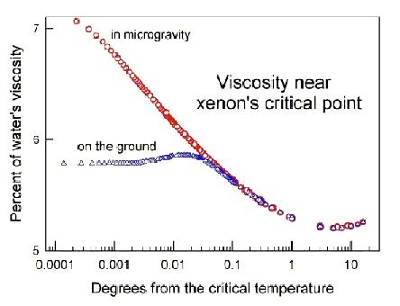
The objective is to measure the viscosity of Xenon at temperatures very near its liquid-vapor critical point (Tc = 16.7º C). CVX is a microgravity experiment with a sensitive, precision hydro-mechanical sensor for measuring viscosity. Temperature scans of the Xenon contained in the sample cell are taken at selected rates near its critical temperature, viscosity measurements are also taken. The data is compared to theoretical values, they provide complementary results to existing ground based test data.
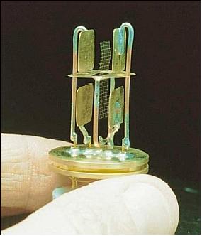
The heart of CVX is a viscometer comprising a nickel screen that vibrates between two pairs of brass electrodes in a xenon bath at the critical point. The grid is 7 mm x 19 mm with a mass of < 1 mg (milligram). An electrode is positioned 4 mm to each side of the screen. An electrical charge applied by the electrodes oscillates the screen. The electrodes then measure the screen's displacement and period, like a pendulum swinging in a liquid. On CVX-1, the screen oscillated at < 13 Hz through a distance of < 0.01 mm, to avoid disrupting the density fluctuations in the xenon.
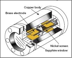
Because the critical condition of xenon requires micro-degree control, the sample cell is a copper cylinder, 62 mm long by 38 mm wide that conducts heat well and adds thermal inertia to ensure slow, even changes in temperature. The cell is enclosed in a three-layer thermostat to improve thermal control.
The CVX-1 experiment was mounted in two adjacent canisters which in turn were mounted on the HH MPESS. One canister housed the EP (Experiment Package), including the viscometer/sample cell, and precision temperature control elements. The second canister housed the AP (Avionics Package), which included the data acquisition and control electronics, and the power conditioning systems. The EP and AP canisters were interconnected via an intercan connect cable for power and data transmission. The EP and AP canisters were each equipped with UEPs (Upper End Plates) to accommodate a cable for power and data transmission that connected the two canisters, and to allow radiative cooling.
In addition to advancing fundamental science, CVX's development fostered several technical innovations. For example, CVX's viscometer is the first to be calibrated by exploiting a hydrodynamic similarity which relates viscosity to frequency. Also, CVX's programmable voltage divider is an innovative circuit which fits on a single electronic card while maintaining voltage stability to within one part per million.
CVX measured the dependence of viscosity on frequency near the critical point of xenon in microgravity. CVX is the first experiment to confirm the theoretical predictions of gravitational effects on liquid-vapor critical phenomena.
References
1) http://www-pao.ksc.nasa.gov/kscpao/chron/sts-85.htm
2) Cryogenic Infrared Spectrometers and Telescopes for the Atmosphere-2 (CRISTA-SPAS-2), URL: http://www-pao.ksc.nasa.gov/kscpao/release/1997/132-97.htm
3) http://science.ksc.nasa.gov/shuttle/missions/sts-85/sts-85-press-kit.txt
4) K. U. Grossmann, D. Offermann, O. Gusev, J. Oberheide, M. Riese, R. Spang, “The CRISTA-2 mission,” Journal of Geophysical Research, Vo, 107, No D23, 2002, doi:10.1029/2001JD000667
5) R. Conway, “MAHRSI Experiment,” URL: http://www.crista.uni-wuppertal.de/campaigns/handbook/hb-iii.html
6) M. H. Stevens, C. R. Englert, M. E. Summers, K. U. Grossmann, O. A. Gusev, “MAHRSI and CRISTA observations of the Arctic Summer Mesosphere, AIAA Space Systems Conference Proceedings, Albuquerque, NM, 2001
7) R. R. Conway, M. H. Stevens, J. G. Cardon, S. E. Zasadil, C. M. Brown, J. S. Morrill, G. H. Mount, “Satellite Measurements of Hydroxyl in the Mesosphere, Geophysical Research Letters, Vol. 23, 1996, pp. 2093-2096
8) M. H. Stevens, R. R. Conway, J. G. Cardon, J. M. Russell III, L. L. Gordley, ”MAHRSI Observations of Nitric Oxide in the Mesosphere and Lower Thermosphere,” Geophysical Research Letters, Vol. 24, pp. 3213-3216,1997
9) Michel D, Ingham, Marie B. Levine, “On-orbit investigation of transient microdynamic disturbances on a deployed truss structure,” URL: http://trs-new.jpl.nasa.gov/dspace/bitstream/2014/18263/1/99-1733.pdf
10) M. B. Levine, “Interferometry program flight experiments: IPEX I and II,” Proceedings of SPIE, Vol. 3350, Astronomical Interferometry, Robert D. Reasenberg, Editor, July 1998, pp. 707-718
11) M. B. Levine, “Microdynamic behavior of a joint dominated structure on-orbit ,” AIAA/ASME/ASCE/AHS/ASC Structures, Structural Dynamics, and Materials Conference and Exhibit, St. Louis, MO, Apr. 12-15, 1999
12) C. Papadimitriou, M. Levine, M. Milman, “Application of a Finite Element Model Updating Methodology on the IPEX-II Structure,” Proceedings. of the 15th International Modal Analysis Conference (IMAC), Santa Barbara, CA, Feb. 1998.
13) L. M. R. Hardaway, L. D. Peterson, “Nanometer-Scale Spontaneous Vibrations in a Deployable Truss Under Mechanical Loading,” AIAA Journal, Vol. 40, No. 10, October 2002
14) M. Ingham, M. Levine, “IPEX-2 Flight Data Analysis: Quiescent Period Report,” NASA/JPL D-17912, June 30, 1999
15) https://web.archive.org/web/20170808211212/http://ssl.mit.edu/publications/theses/PhD-1998-KimYool.pdf
16) J. D. Spinhirne, V. S. Scott, J. Cavanaugh, S. Palm, K. Manizade, J. W. Hoffman, R. C. Grush, “Preliminary Spaceflight Results from the Uncooled Infrared Spectral Imaging Radiometer (ISIR) on Shuttle Mission STS-85,” SPIE, 1998
17) J. W. Hoffman, R. C. Grush, “Design and fabrication of the Infrared Spectral Imaging Radiometer (ISIR),” Proceedings of SPIE, 'Multispectral Imaging for Terrestrial Applications II,' Joan B. Lurie, Thomas Delaney, Editors, Vol. 3119, Sept. 1997, pp. 68-79
18) J. D. Spinhirne, R. S. Lancaster, K. R. Maschhoff, “Application and design of satellite Infrared Spectral Imaging Radiometers with uncooled microbolometer array detectors,” AMS (American Meteorological Society) Conference, URL: http://ams.confex.com/ams/pdfpapers/24341.pdf
19) R. S. Lancaster, J. D. Spinhirne, K. F. Manizade, “Combined Infrared Stereo and Laser Ranging Cloud Measurements from Shuttle Mission STS-85,” Journal of Atmospheric and Oceanic Technology, Vol. 20, Issue 1, 2003, pp. 67-78
20) http://denali.gsfc.nasa.gov/research/laser/sla/sla1.html
21) http://denali.gsfc.nasa.gov/sla/sla02/sla02.html
22) J. B. Garvin, J. Bufton, J. B. Blair, D. Harding, S. Luthcke, J. Frawley, D. Rowlands, “Observations of the Earth's topography from the Shuttle Laser Altimeter (SLA): laser-pulse echo-recovery measurements of terrestrial surfaces,” Physics and Chemistry of the Earth, Vol. 23, No 9-10., 1998, pp.1053-1068
23) “Stirring Up an Elastic Fluid, Critical Viscosity of Xenon–2 (CVX–2),” URL: http://spaceresearch.nasa.gov/sts-107/107_cvx.pdf
24) “Critical Viscosity of Xenon-2 (STS-107),” URL: http://spaceresearch.nasa.gov/sts-107/107_cvx.pdf
The information compiled and edited in this article was provided by Herbert J. Kramer from his documentation of: ”Observation of the Earth and Its Environment: Survey of Missions and Sensors” (Springer Verlag) as well as many other sources after the publication of the 4th edition in 2002. - Comments and corrections to this article are always welcome for further updates (eoportal@symbios.space).