SNOE (Student Nitric Oxide Explorer)
EO
Atmosphere
Mission complete
CU Boulder
Quick facts
Overview
| Mission type | EO |
| Agency | CU Boulder |
| Mission status | Mission complete |
| Launch date | 26 Feb 1998 |
| End of life date | 13 Dec 2003 |
| Measurement domain | Atmosphere |
| CEOS EO Handbook | See SNOE (Student Nitric Oxide Explorer) summary |
SNOE (Student Nitric Oxide Explorer)
SNOE was a small satellite student project of the University of Colorado (CU) at Boulder, CO with the objective to measure the altitudinal density variation of nitric oxide in the atmosphere. In 1995, the SNOE project was selected as one of three small satellite projects within the STEDI (Student Explorer Demonstration Initiative) program, an initiative funded by NASA and managed by USRA (Universities Space Research Association).
The SNOE spacecraft and its instrument complement were designed, built, and operated at LASP (Laboratory for Atmospheric and Space Physics) of CU (PI: C. Barth). There was student involvement in all aspects of the project, the design and construction phase alone involved about 110 CU students, primarily undergraduates. In addition, there was collaboration with Ball Aerospace, NCAR, JPL, and Arapahoe High School of Littleton, CO. The science objectives of SNOE were to measure nitric oxide density in the terrestrial lower thermosphere (90-200 km) and to analyze the energy inputs to that region from the sun and magnetosphere that create this compound and cause its abundance to vary dramatically. 1) 2) 3) 4) 5) 6) 7)
Spacecraft
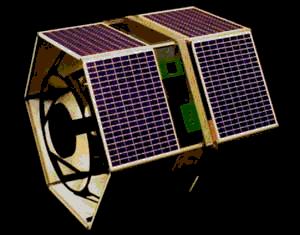
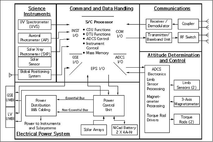
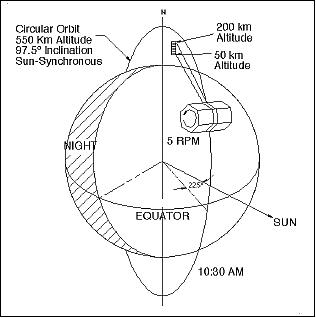
The S/C is a compact hexagonal modular structure, 0.95 m high and 1 m across its widest dimension. The satellite is spin stabilized at a spin rate of 5 rpm with the spin axis normal to the orbit plane. Attitude knowledge is provided by horizon crossing indicators, and magnetometers; attitude control is done with torque rods and nutation dampers. The S/C employs passive thermal control. Power = 35 W; data rate = 6 MByte/day. S/C mass = 115 kg. The mission design life is one year.
The structural solution to the spacecraft design involves four primary structural components: 1) the spacecraft equipment and instrument mounting plate; 2) the adapter structure that mates the spacecraft to the launch vehicle. This structure has provision for a separation assembly (marmon clamp and actuator) to release the spacecraft on orbit after positioning and spin-up; 3) two solar array assemblies and their support structure; and 4) two antenna masts.
The central mounting plate provides support for the spacecraft electronics, instruments and cables, and the launch adapter structure. It mounts both of the solar array structures and the antenna mast assemblies. It provides also a thermal path for heat generated in the interior of the spacecraft to reach the thermal radiators. The central mounting plate is fabricated from two weight-relieved aluminum plates bolted together in a clamshell arrangement.
There are two patch antennas located on the spin axis at each end of the spacecraft. The antennas consist of a support tube and a thin plate. This assembly mounts to each side of the central mounting plate. The column provides structural support for the antenna, and precisely positions it so that the ground plane of the antenna sits above the solar panel.
Attached to the central mounting plate, around the periphery of the hex, are six 0.25 mm aluminum radiator panels. Three of these panels have apertures for the science instruments and sensors located on the spacecraft. The radiators are coated with a durable ceramic surface to maintain radiative properties so that operating temperatures are controlled.
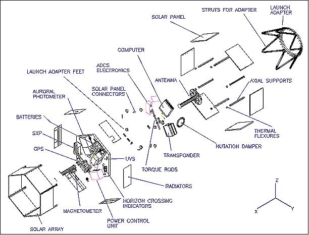
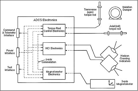
ADACS (Attitude Determination and Control Subsystem): The requirements of the spin-stabilized spacecraft permit a spin axis pointing within 5º of the orbit normal, and to maintain the spin rate between 4 and 6 rpm. The attitude is sensed by two pyroelectric horizon crossing indicators (HCIs) and a three axis fluxgate magnetometer. Actuation is provided by two magnetic torque rods, one directed along the spin axis and the other directed normal to the spin axis. Passive nutation damping is provided by an alcohol-filled ring damper, mounted perpendicular to the central plate of the satellite. Active nutation can be implemented if needed, using a B-dot law on the spin axis torque rod only. The ADACS system is controlled by an independent electronics module, which provides the command and data interface to the flight computer.
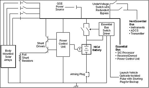
The EPS (Electric Power Subsystem) is a direct energy transfer system that generates energy, stores energy for use during orbit eclipse, and controls the distribution of energy to the required S/C and payload systems. Power is distributed at 28 V ±4 V. Power is generated by surface-mounted panels of solar arrays. There are twelve rectangular panels, each containing 2 array circuits (strings) for total of 24 strings. Energy is stored in two 22-cell 4 Ah Nickel Cadmium (NiCd) battery packs.
The C&DH (Command and Data Handling) subsystem consists of a flight computer and five I/O blocks on two daughter boards. The I/O blocks handle interfacing the computer to all S/C subsystems. The flight computer used is an SC4A Single Board Spaceflight Computer developed by Southwest Research Institute (SwRI).
RF communications are provided in S-band. The S-band system consists of a transmitter, receiver/demodulator, hemispherical antennas, coupler, RF switch, and filter. The downlink data rate is 128 kbit/s, the modulation is PCM/PSK/PM. The uplink data rate is 2 kbit/s NRZ-M using PCM/PSK/PM modulation. The communications protocol employs the CCSDS standard. Mission operations for SNOE are being performed at LASP of the University of Colorado at Boulder with tracking and communication services provided by NASA. The science data of SNOE are made available to the science community.
Launch
The SNOE S/C was launched on a Pegasus XL vehicle of OSC (along with Teledesic LLC's T1 satellite - the world's first commercial Ka-band LEO satellite) on Feb. 26, 1998. The launch originated from VAFB, CA, USA.
Orbit: Sun-synchronous polar near-circular orbit, altitude of 525 km x 580 km, inclination = 97.75º, equator crossing at 10:30 AM.
Mission operations were conducted at POCC (Project Operations and Control Center) of LASP. Students were the flight controllers monitoring the satellite as well as the flight engineers providing scheduling functions and performance analysis.
Mission Status
• The SNOE satellite was operated and data collected throughout its entire mission life of nearly 6 years. The spacecraft reentry took place on Dec. 13, 2003 on orbit 32248, after 5 years and 290 days in space.
• SNOE observations confirmed previously held suspicions that the solar soft X-ray irradiance was stronger than the prior sparsely available data and empirical models suggested. SNOE demonstrated that solar soft X-ray irradiance and auroral energy deposition control the abundance of NO over the globe, but provided the very surprising results that wintertime midlatitude NO is controlled by auroral energy while summertime polar NO is controlled by solar irradiance. The morphology of NO is also providing clues to the processes in the magnetospheric which lead to the auroral energy deposition. 8)
Sensor Complement
UVS (Ultraviolet Spectrometer)
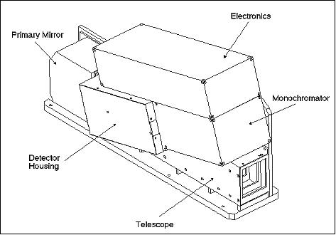
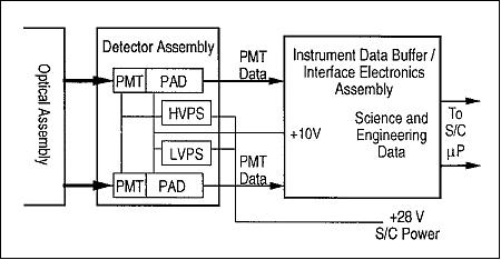
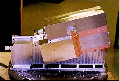
UVS is a limb-viewing instrument with the objective to measure the densities of nitric oxide in the altitude range of 50-200 km by observing the (1,0) and (0,1) gamma bands. UVS is of NDS (Nitrogen Dioxide Spectrometer) heritage flown on SME (Solar Mesosphere Explorer, launch Oct. 6, 1981). UVS consists of an Ebert-Fastie spectrometer, an off-axis telescope, and two Hamamatsu PMT detectors. The spectrometer has a focal length of 125 mm and uses 3600 lines/mm mechanically ruled plane grating, which produces a dispersion of 2.15 nm/mm at the detectors. The grating in the spectrometer is set to place the (1,0) gamma band (215 nm wavelength) on one detector and the (0,1) gamma band (237 nm wavelength) on the other detector. Both channels have a sensitivity of ~1.1 counts/second/Rayleigh. - UVS is mounted with its optical axis perpendicular to the S/C spin axis. Its telescope images the entrance slit of the spectrometer on the limb. The image of the slit is 7 km high (resolution). The integration time is 28 ms for 2x spatial oversampling. 9)
Spectrometer | Telescope | ||
Instrument type | Ebert-Fastie | Mirror system | Single mirror off-axis paraboloid |
Focal length, focal ratio | 125 mm, f/5 (zero order) | Off-axis angle | 15º |
Wavelength coverage (nm) | 215 (cha. 1), 236.5 (cha. 2) | Focal length | 250 mm |
Wavelength bandpass (nm) | 1:3.8 (cha. 1); 2:3.7 (cha. 2) | Focal ratio | f/5 |
Wavelength dispersion | 1.8 nm/mm | Effective collection area | 20.7 cm2 |
Entrance slit, exit slit (mm) | 0.31 x 3.2; 2 x 4 | Material | Fused silica |
Grating angle | 22.7º (to slit plane) | Coating | Al, MgF overcoat |
Exit slit separation | 10.8 nm | Field of View (FOV) | 0.071º x 0.75º |
AP (Auroral Photometer)
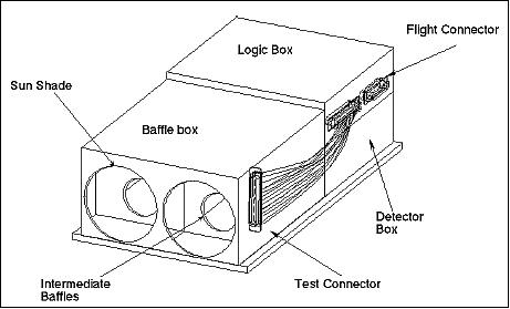
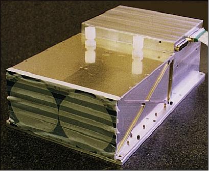
AP is a two-channel broadband nadir-viewing instrument with the objective to observe UV emissions from the aurora and to determine the energy deposited in the upper atmosphere by energetic auroral particles. The channels (A and B) consist of two Hamamatsu PMT detectors, a US window/filter for each channel, and a FOV limiter. FOV = 11º (full cone) for each channel. Spectral range observed = 125-180 nm for channel A and 135-180 nm for channel B. The sensitivity of channel A at 130.4 nm is ~70 counts/second/Rayleigh; the sensitivity of channel B at 135.6 nm is ~27 counts/second/Rayleigh. - The AP instrument is mounted with its optical axis perpendicular to the S/C spin axis. The integration time for each channel is 187 ms, providing 32 samples per channel per spin. 10)
SXP (Solar X-ray Photometer)
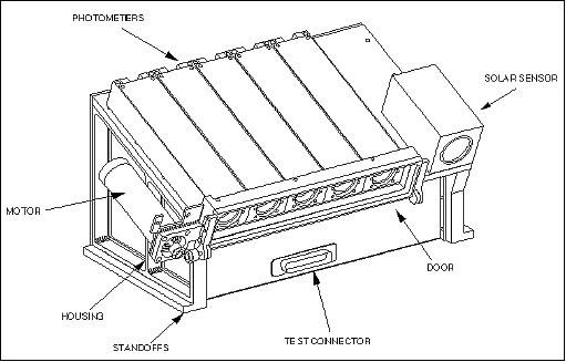
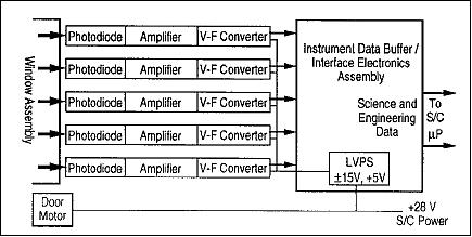
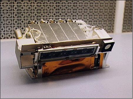
A sun-viewing instrument with the objective to measure the solar soft X-ray flux within a FOV of ±35º of the local zenith direction in the spectral range of 2-31 nm. Each of the five photometer channels contains a silicon photodiode detector; the wavelength selection is accomplished by thin metallic films deposited directly onto the diode surface. The integration time is 62.5 ns. A small two-axis sun sensor is co-aligned with SXP to measure the solar incidence angle for the instrument. 11)
BGSR (microGPS - Bit Grabber Space Receiver)
The receiver is provided by JPL for orbit determination of SNOE (cooperation with the University of Colorado at Boulder). Instrument size: 6.3 cm x 11.5 cm x 5 cm, mass of 0.68 kg, power of 2.1 W (while operating, but 0.02 W on orbit average). The GPS orbit is determined about three times per orbit for short time intervals, otherwise the receiver is in hibernation. The information is used for post-factum ground orbit determination.
References
1) Stanley C. Solomon, Scott M. Bailey, Charles A. Barth, Randal L. Davis, John A. Donnelly, Timothy E. Holden, Michelle S. Kelley, Richard A. Kohnert, Michael T. McGrath, Aimee W. Merkel, Heather L. Reed, Sean M. Ryan, Mark A. Salada, Stephen R. Steg, Gail A. Tate, James C. Westfall, Jason J. Westphal, and Peter R. Withnell, “The SNOE Spacecraft: Integration, Test, Launch, Operation, and On-orbit Performance,” Proceedings of the 12th Annual AIAA/USU Conference on Small Satellites, Logan, UT, USA, Aug. 31-Sept. 3, 1998, URL: http://lasp.colorado.edu/snoe/publications/pdf_docs/AIAAitlop.pdf
2) Stanley C. Solomon, Charles A. Barth, Penina Axelrad, Scott M. Bailey, Ronald Brown, Randal L. Davis, Timothy E. Holden, Richard A. Kohnert, Frederick W. Lacy, Michael T. McGrath, Darren C. O’Connor, Jeffrey P. Perich, Heather L. Reed, Mark A. Salada, John Simpson,
Jeffrey M. Srinivasan, George A. Stafford, Stephen R. Steg, Gail A. Tate, James C. Westfall, Neil R. White, Peter R. Withnell, and Thomas N. Woods, “The Student Nitric Oxide Explorer,” 'Space Sciencecraft Control and Tracking in the New Millennium,' Proceedings of SPIE, Vol. 2810, 1996
3) Information provided by Stanley C. Solomon, University of Colorado at Boulder
4) S. C. Solomon, et al., “The Student Nitric Oxide Explorer,” Proceedings of the 9th Annual AIAA/USU Conference on Small Satellites, Utah State University, Logan, Utah, 1995
5) Scott M. Bailey, Charles A. Barth, Michael J. Erickson, Richard A. Kohnert, Aimee W. Merkel, Erica M. Rodgers, Stanley C. Solomon, Stanley D. Straight, James E. Vian, “Science Instrumentation for the Student Nitric Oxide Explorer,” Proceedings of SPIE, Vol. 2830, Denver, CO, USA, Aug. 5-9, 1996, URL: http://lasp.colorado.edu/snoe/publications/pdf_docs/instruments.pdf
6) http://lasp.colorado.edu/snoe/
7) http://nasascience.nasa.gov/missions/snoe
8) S. M. Bailey, “The Achievements of the Student Nitric Oxide Explorer,” American Geophysical Union, Fall Meeting, San Francisco, CA, USA, Dec. 5-9, 2005
9) A. W. Merkel, C. A. Barth, “Altitude determination of ultraviolet measurements made by the Student Nitric Oxide Explorer,” Journal of Geophysical Research, Vol. 106, No A12, Dec. 1, 2001, pp. 30,283-30,290
10) S. C. Solomon, Ch. Barth, S. M. Bailey, “Auroral production of nitric oxide measured by the SNOE satellite,” Geophysical Research Letters, Vol. 26, No 9, May 1, 1999, pp. 1259-1262
11) S. M. Bailey, T. N. Woods, C. A. Barth, S. C. Solomon, “Measurements of the solar soft x-ray irradiance from the Student Nitric Oxide Explorer,” Geophysical Research Letters, Vol. 26, No 9, May 1, 1999, pp. 1255-1258
The information compiled and edited in this article was provided by Herbert J. Kramer from his documentation of: ”Observation of the Earth and Its Environment: Survey of Missions and Sensors” (Springer Verlag) as well as many other sources after the publication of the 4th edition in 2002. - Comments and corrections to this article are always welcome for further updates (eoportal@symbios.space).