SOCRATES (Space Optical Communications Research Advanced Technology Satellite)
EO
Atmosphere
Mission complete
NICT
Quick facts
Overview
| Mission type | EO |
| Agency | NICT |
| Mission status | Mission complete |
| Launch date | 24 May 2014 |
| End of life date | 24 May 2019 |
| Measurement domain | Atmosphere |
| CEOS EO Handbook | See SOCRATES (Space Optical Communications Research Advanced Technology Satellite) summary |
SOCRATES (Space Optical Communications Research Advanced Technology Satellite)
Spacecraft Launch Mission Status Experiments Optical Ground Station References
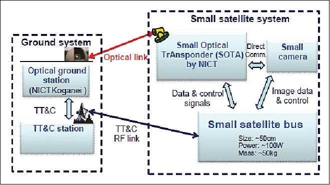
SOCRATES is a microsatellite mission of NICT (National Institute of Information and Communications Technology), Koganei, Tokyo, Japan. The overall objective is to demonstrate and validate the operation of SOTA (Small Optical TrAnsponder), a laser communication system in space. The goal is to experiment with QKD (Quantum Key Distribution) techniques and to foster the application free-space optical communications (higher data rates than RF communications) in microsatellites and eventually in nanosatellites. 1) 2) 3) 4)
SOTA is controlled via the TT&C (Tracking Telemetry and Command) link from the TT&C RF ground station. The laser communication experiment is conducted between SOTA and OGS (Optical Ground Station) located at NICT. The establishment of 10 Mbit/s communication links is the main mission of SOCRATES (measurement of the laser beam propagation through turbulent atmosphere at difference of wavelengths). By using the laser communication links, the propagation data at wavelengths of 1.5 µm and 1.06 µm can be measured.
Spacecraft
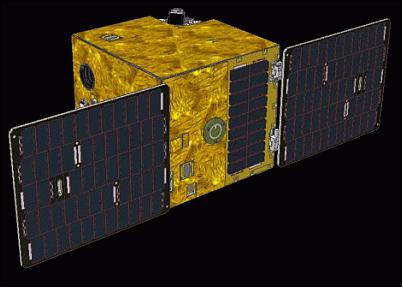
The SOCRATES microsatellite, developed for NICT by AES (Advanced Engineering Services Co.,Ltd.), Tsukuba, Japan, employs the small satellite standard bus. The objective of the mission is to demonstrate the operation of the small standard satellite bus. 5) 6)
Mission success | - Confirmation of the most basic components operation capabilities consisting of satellite bus in orbit. |
Full success | - Confirmation of all components of the bus will operate properly in orbit. |
Extra success | - In addition to normal operations of mission equipment, contribution for experiment through stable attitude control and power based on the needs of users. |
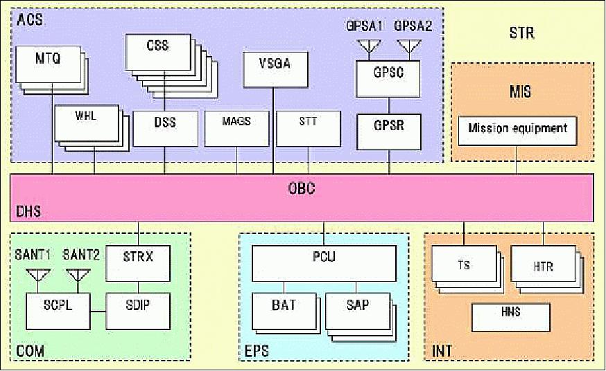
The standard bus is comprised of the following subsystems:
1) STR (Structure)
2) EPS (Electrical Power Subsystem) with PCU (Power Control Unit), SAP (Solar Array Panel) and BAT (Battery).
3) DHS (Data Handling Subsystem) with OBC (OnBoard Computer)
4) RF communication subsystem, consisting of SANT (S-band antenna), SCPL (S-band Coupler), SDIP (S-band Diplexer), and STRX (S-band Transponder).
5) ACS (Attitude Control Subsystem), consisting of MTQ (Magnetic Torquer), WHL (Wheel), DSS (Digital Sun Sensor), CSS (Coarse Sun Sensor), MAGS (Magnetic Sensors), VSGA (Vibrating Structure Gyroscope Assembly), GPSA (GPS Antenna), GPSC (GPS Coupler), and GPSR (GPS Receiver).
6) INT (integration hardware), consisting of TS (Temperature Sensors), HTR (Heater), and HNS (Harness).
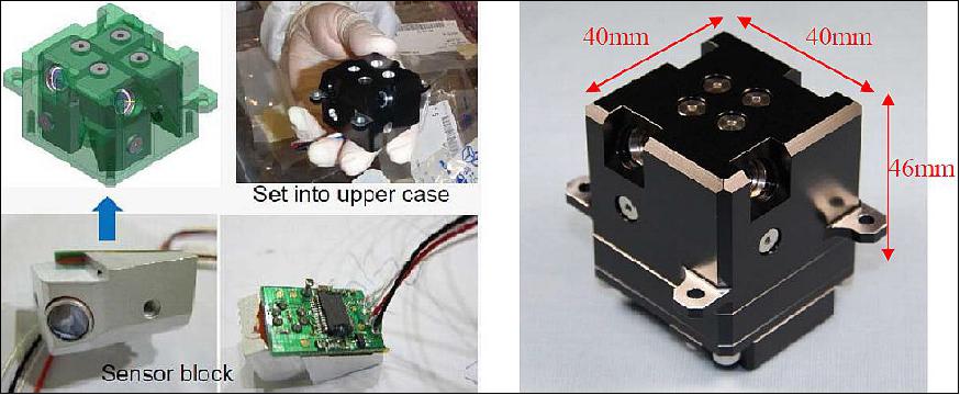
JAXA and MEC (Meisei Electric Company) developed MESA (Micro Earth Sensor Assembly) applying COTS based 4 thermopile arrays. The size of MESA is 40 x 40 x 50 mm excluding flange with a mass of 137 g. MESA provides 2D attitude information with an accuracy of <1º. MESA is a technology demonstration device on SOCRATES. 7)
MESA is not included in onboard realtime attitude control system, because it has no flight heritage yet. In order to evaluate performance of MESA, output of each detector and relating raw data during earth attitude control mode of SOCRATES such as sun pointing mode or Earth pointing mode are obtained.
MESA data are downloaded in order to compare with the data of the star tracker, STR. With evaluating attitude obtained by MESA and STR, it is confirmed that the accuracy of attitude determination with MESA is generally less than 1º.
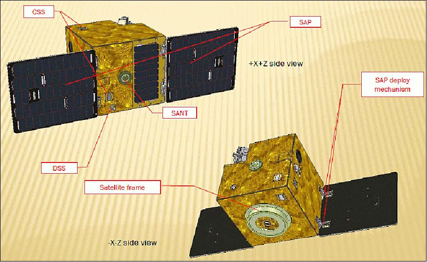
Spacecraft mass | 48 kg |
External dimensions of the spacecraft | W 496 x D495 x H485 mm (SAP is folded during launch) |
Power generation | ~100 W (nominal), 120 W (max), use of SAP deployment mechanism |
ACS (Attitude Control Subsystem) | Three axis stabilized attitude control, solar pointing control, earth pointing control |
RF communications | S-band |
Launch
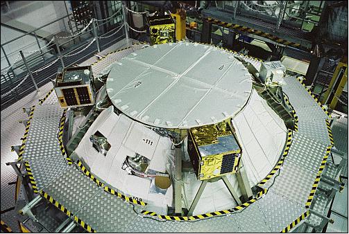
The SOCRATES microsatellite was launched as a secondary payload on May 24, 2014 (03:05 UTC) on a H-IIA vehicle from TNSC (Tanegashima Space Center), Japan. The launch provider was MHI (Mitsubishi Heavy Industries, Ltd.). The primary payload on this flight was the ALOS-2 (Daichi-2) spacecraft of JAXA. 8)
The secondary missions manifested on the ALOS-2 mission by JAXA were: 9)
• Rising-2, a cooperative microsatellite (43 kg) project of Tohoku University (Sendai) and Hokkaido University, Sapporo, Japan.
• UNIFORM-1 (University International Formation Mission-1), of Wakayama University, Wakayama, Japan.
• SOCRATES (Space Optical Communications Research Advanced Technology Satellite), a microsatellite (48 kg) mission of NICT (National Institute of Information and Communications Technology), Koganei, Japan.
• SPROUT (Space Research on Unique Technology), a nanosatellite of ~7 kg of Nihon University, Tokyo, Japan.
Orbit: Sun-synchronous near-circular sub-recurrent orbit, altitude = 628 km, inclination = 97.9º, period = 97.4 minutes, LSDN (Local Sun time on Descending Node) = 12:00 hours ± 15 min.
Mission Status
• July 11, 2017: NICT developed the world's smallest and lightest quantum-communication transmitter (SOTA) onboard the microsatellite SOCRATES. The project succeeded in the demonstration of the first quantum-communication experiment from space, receiving information from the satellite in a single-photon regime in an optical ground station in Koganei city. SOTA has a mass of 6 kg and its size is 17.8 cm length, 11.4 cm width and 26.8 cm height. It transmits a laser signal to the ground at a rate of 10 Mbit/s from an altitude of 600 km at a speed of 7 km/s. The project succeeded in correctly detecting the communication signal from SOTA moving at this fast speed. This is a major step toward building a global long-haul and truly-secure satellite communication network. 10) 11)
- As a result of this research, NICT demonstrated that satellite quantum communication can be implemented with small low-cost satellites, which makes it possible to many research institutions and companies to use this key technology. It is an achievement that opens a new page in the development future global communication networks, being a big boost to the space industry.
• Sept./Oct. 2016: The SOTA (Small Optical TrAnsponder) lasercom terminal onboard the SOCRATES satellite has been operated by NICT for around two years. In this time, all the goals of the mission have been achieved, including up to 10 Mbit/s downlinks using two different wavelengths and apertures, verification of coarse and fine tracking of the OGS (Optical Ground Station) beacon, space-to-ground transmission of pseudo-random sequences and images from the on-board-camera as well as preloaded samples, and experiments with different error correcting codes. At the moment, two extra-success phases of the mission are ongoing: interoperability with other international OGS and basic experiments on space QKD (Quantum Key Distribution). 12)
• The SOCRATES spacecraft and its payload are operating nominally in the spring of 2016. 13)
- The space-to-ground laser communication experiments have been conducted with SOTA. Atmospheric turbulence causes signal fadings and becomes an issue to be solved in satellite-to-ground laser communication links. Therefore, as error-correcting functions, a Reed-Solomon (RS) code and a Low-Density Generator Matrix (LDGM) code are implemented in the communication system onboard the SOTA. Almost all of the success criteria have been met. It was confirmed that even stronger receiving power than predicted by the previous optical link design was received in the experiment. Also, a comparison of the optical link design and approximately ±2 dB under the Rytov approximation showed similar results. The data recovery with an error-correcting code from the packet loss due to atmospheric fluctuations and tracking errors was also confirmed. 14)
- In 2015, the first links between the SOCRATES microsatellite atLEO and an OGS (Optical Ground Station) in Europe has been established with two different wavelengths and at several OGS apertures (collaboration between CNES, NICT, and Geoazur). Acquisition and tracking were successfully performed during the various passes. Basic data such as power fluctuation, frequency spectrum, telecom data and BER were obtained. The telecom link quality is almost good at 1.5 m and 0.4 m OGS aperture, and it is limited at 0.2 m OGS aperture. Optical power levels detected at OGS and at SOTA match well with theoretical estimation. 15)
• July, 2015: NICT started experimental verification of optical satellite communications using SOTA (Small Optical TrAnsponder) last September. A practical fading generator with respect to collected experimental data has been developed for communications system design. The fading generator consists of two components: fade level and noise variance generators based on model fitting the corrected data into theoretical atmospheric turbulence distribution. 16)
- The OPTical communications working group (OPT) of the SLS (Space Link Services) in CCSDS (Consultative Committee for Space Data Systems) is in charge of optical satellite communication systems. The low complexity system with OOK (On-Off Keying) modulation is one of the categories for physical layer standardization by SLS-OPT. The OOK based IM/DD (Intensity Modulation with Direct Detection) format is preferred to enable a simple, robust, and cost-effective setup for optical satellite communications, especially in LEO (Low Earth Orbit) satellite applications. The practical system performances must be evaluated to edit the Green/Blue Books.
In optical satellite communications, an atmospheric turbulence affects received signals. Burst errors and tracking difficulties due to fading seriously degrade performances. Therefore, it is desirable to model a practical fading channel by reflecting accurate statistics with atmospheric turbulence-induced signal fade based on measurements.
- NICT initiated an R&D effort of SOTA (Small Optical TrAnsponder) for LEOs to demonstrate the attractive features of optical technology in the frame of the SOCRATES (Space Optical Communication Research Advanced TEchnology Satellite) project. The SOTA measurement campaign started in September 2014, and different test scenarios have been conducted to understand characteristics of optical satellite channel. The experimental data obtained by SOTA campaign has been utilized for the channel modeling. The fading generator based on the measurements has been developed using model fitting technique. The system performances in optical satellite channel can be easily simulated by implementing in the fading generator.
- Evaluation of SOTA downlink signals: The SOTA measurement campaign has been performed in order to collect downlink signals with different data formats such as image data and Pseudo-random Noise (PN) sequences. The project focuses on the format of PN sequence with the period of 215-1 called "PRBS 15" due to a known data sequence. The specifications of the downlink signals are listed in Table 3. The data collection system including SOTA receiver and digital storage oscilloscope (DSO) as shown in Figure 7. The received optical satellite downlink signal is passed to APD (Avalanche Photo Diode) to convert into an electrical one, followed by loopback modules including two LPFs (Low-Pass Filters), A/D and D/A converters. The output loopback electrical signals are stored in DSO at a sampling frequency of 50 MHz in time interval of every 4 s. A length of single snapshot is 4e6 samples (0.08 s) due to the limitation of DSO. There are 456 PN sequences in a single path.
Wavelength | 1549 nm |
Transmit power (average) | 34.8 nW |
Tx antenna diameter | 8.1 nm |
Modulation | NRZ-OOK (Non-Return to Zero/On-Off Keying) |
Modulation symbol rate | 10 Msps |
Propagation distance | 600 - 1000 km |
RX antenna diameter | 1 m |
Photodetection technique | IM/DD |
RX detector | InGaAs APD (Avalanche Photo Diode) |
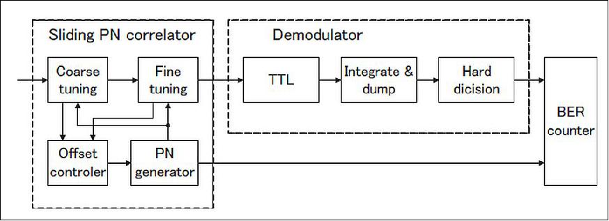

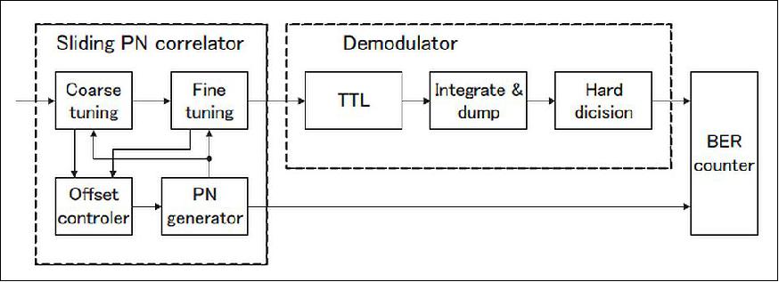
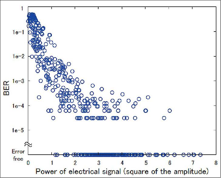
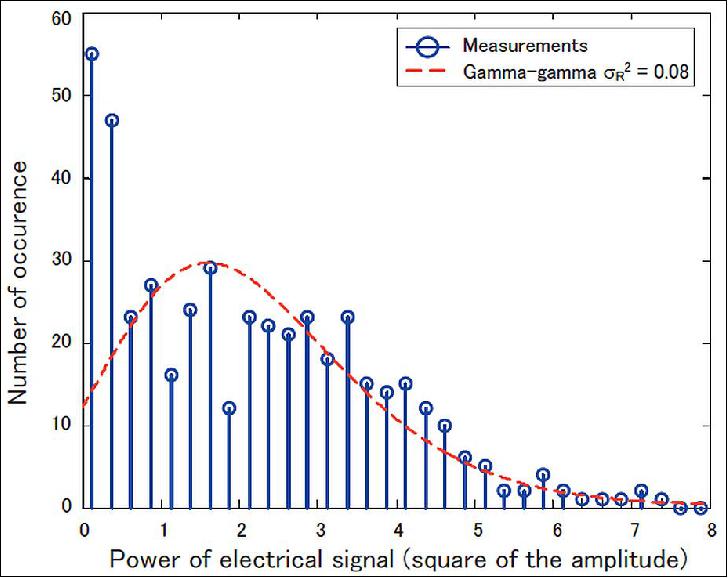
The collected snapshots in two channel environments, falloff and strong signals, are shown in Figure 8 (a) and (b), respectively. 24 PN sequences are continuously sampled in a snapshot. The stored electrical signals in DSO are demodulated by offline receiver as shown in Figure 9. A sliding PN correlator finds the optimum start point of each PN sequence. A TTL (Time Tracking Loop) tracks timing shift due to oscillator and Doppler shift. The synchronized signals are integrated over its oversampling ratio of 5 samples and dumped. The dumped symbols are determined as "0" or "1" by hard decision, and then BERs (Bit Rate Errors) over each PN period are calculated. In subsequent discussion, we analyze the collected data in a single path, since available data is obtained on a day only. The BER distribution during the single path is calculated by plotting BER of each PN period versus electrical signal power as shown in Figure 10. There are 28 % of error free PN sequences more than the signal power of 1.1. The electric power is calculated by averaging square of the amplitude over PN period. The obtained histogram is shown in Figure 11. The experimental power distribution plotted with the blue circles does not indicate a smooth line due to the small number of collected samples.
- System demonstration: The fading generator is implemented as a part of system simulator as shown in Figure 7. The block diagram consists of OOK modulator/demodulator, convolutional interleaver/deinterleaver, LDPC (Low Density Parity Check) encoder/decoder, and fading generator. The system specifications are listed in Table 2. The LDPC code according to CCSDS 131.0-B-1 6) is adopted to correct errors due to fading. The input to the LDPC decoder is soft decision demodulated signals to improve coding gain obtained by a MAP (Maximum A posteriori Possibility) decoding algorithm called modified BCJR algorithm. The soft decision threshold value is heuristically found to obtain the minimum BER. The interleaver also plays an important role in communications in fading channel, since the spreading out of burst errors caused by fading is accomplished. The deinterleaved soft decision signals are suitable for the LDPC decoder. Note that the lowest value of the noise variance generator is limited to 0 dB, since the receiver can not be synchronized with the incoming signals under the SNR of 0 dB. To evaluate performances, the system is demonstrated by implementing a signal processing worksystem (SPW). 17)
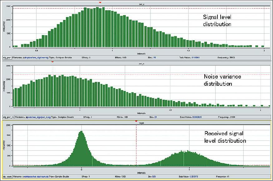
The distributions obtained from the fading generator are shown in Figure 12. The upper and the middle figures are histograms corresponding to outputs from fade level and noise variance generator, respectively. The distribution of received signals is shown in the lower figure. The two peaks correspond to transmitted OOK signals assigned by sign of "0" and "1", but each signal spreads out due to fading.
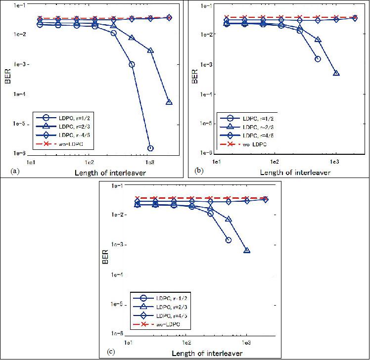
The BER performances for different lengths of the interleaver are shown in Figure 13, which is plotted on a logarithmic scale. The x-axis presents the length of interleaver and the y-axis presents the BER. In Figure 13 (a), (b) and (c), the BER for the three coding rate are plotted as the length of information bits of LDPC code, 1024, 4096 and 16384, respectively. For comparison, the BER performances without LDPC decoding are also plotted as the broken red line. The BER is improved as the length of information bits increases, since the LDPC codes with longer information bits have higher coding gain. The error free transmission for coding rates of 1/2 and 2/3 cases with interleaver length of more than 255 can be seen in Figure 13 (b) and (c). However, a coding rate of 4/5 can not improve the BER because of insufficient coding gain.
In summary, the experimental data obtained by SOTA campaign has been analyzed, and the fading generator based on the results has been developed by using atmospheric turbulence model. After collecting sufficient number of experimental data, the more optimal parameters of fading generator will be found. The proposed fading generator of NICT will provide a comprehensive optical satellite downlink channel characterization.
• April 2015: The Socrates microsatellite is operating nominally.
Sensor Complement
SOTA (Small Optical TrAnsponder)
After the successful laser communication demonstrations between space and the optical ground stations in NICT and other international stations, using LUCE (Laser Utilizing Communications Equipment) onboard OICETS (Optical Interorbit Communications Engineering Test Satellite), NICT initiated its R&D activities of SOTA for microsatellites within the frame of the SOCRATES (Space Optical Communication Research Advanced Technology Satellite) project. 18) 19) 20) 21) 22) 23)
The objectives of SOTA are:
• On orbit acquisition, tracking and communication performance verification of the small optical terminal
• To acquire propagation data through the atmosphere at various wavelengths
• Communication quality measurement
• To determine the effect of coding on the communication quality
• Basic experiment for QKD (Quantum Key Distribution)
• Experiments with international OGSs (Optical Ground Stations)
• Command operation by optical link (future)
• Link experiment with aircraft (future)
• Link experiment with satellite (future).
The SOTA instrumentation was designed and developed at NICT in cooperation with NEC Corporation, NEC Toshiba Space Systems, Ltd.
The development of SOTA started based on the proposed BBM (Bread Board Model) from an industry team. The model consisted of an optical part (SOTA-OPT) and a controller (SOTA-CONT). In the optical part, two AQD (Acquisition Quadrant Detectors) and for tracking (T-QD), four laser transmitters and a 45 mm diameter receiving optics with a FQD (Fine-pointing Quadrant Detector), FPM (Fine Pointing Mechanism), and an APD (Avalanche Photo Diode) were installed on the optical bench.
The optical bench was mounted on an Elevation (El) actuator and Azimuth (Az) rotational table. These tables were COTS (Commercial off-the-Shelf) devices which needed some modifications for space application. The main design parameters are listed in the Table 4. Figure 14 shows the configuration of the BBM.
Instrument mass, power | 5.86 kg, 22.8 W |
Instrument size | Optical part: 178 W x 114 D x 1268 H (mm) |
Acquisition and tracking | Angular range: Az: >±10º, El: >±10º |
Communication | |
Link range | 1000 km |
Wavelength | TX 1: 976 nm |
Data rate | 10 Mbit/s |
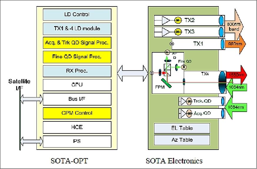
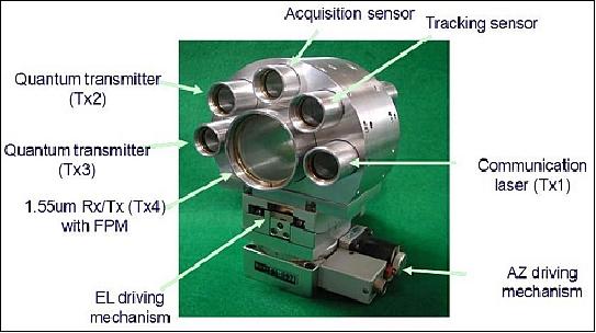
After review and discussion of the BBM design, it was pointed out that the following technologies should be verified by an EM (Engineering Model).
A new 2-axes gimbal EM and a receiving optics EM were designed and manufactured with some related electronic circuits for evaluation. Figure 16 shows the engineering model of the 2-axes gimbal with integrated receiving optics. The size of the gimbals is 207 W x 178 D x 280 H (mm).
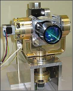
The main parameters of the 2-axes gimbal are listed in Table . The angular range of ±10º in the BBM was expanded to ±45º. Micro-stepping motors with harmonic drives® which a reduction ratio of 100 were used in both Azimuth and Elevation axes.
Actuator | Step drive motor with Harmonic Drive (HD)® reduction ratio of HD® : 1:100 |
Angular range | Az: ±45º EL : ±45ºl |
Drive | Micro-step drive |
Angular rate max | 3deg/s @2667 pps(pulses per second) |
Resolution | 0.001125º/pulse |
Size | 207 W x 178 D x 280 H (mm) |
The 2-axes gimbal is controlled by a pulse count without additional an angular encoder. In this case the backrush property is very important for precise control of the gimbal. Figure 17 shows the measured drive angle vs. cumulative command pulse count. A backrush of 20 arcsec was identified. This property was modeled and embedded in the simulation model of the gimbal control for precise analysis.

The mechanical properties of the 2-axes gimbal, such as fundamental frequency and quiescence during vibration, are very important for the onboard equipment. The 2-axes gimbal EM was evaluated by a vibration test with dummy harness.
SOTA PFM (Proto-Flight Model)
Major modifications of the SOTA PFM design from BBM and EM design are:
• The width of the 2-axis gimbal is reduced to 177 mm
• The beam expender in the receiving optics is replaced with a Cassegrain telescope which is very small and of low mass. And the diameter of telescope is increased to 5 cm.
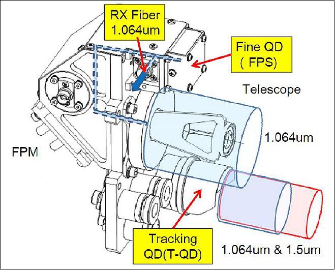
• The acquisition QD and the tracking QD are replaced by one detector, referred to as T-QD, with an increased aperture diameter of 2.3 cm.
The SOTA has four transmitters (TX1~4) which operate at 980 nm (TX1), 800 nm band (TX2 and 3) and 1550 nm (TX4). TX1 and TX4 transmit an optical signal which is selectable from data sources of PN,; the image data and telemetry data of SOTA have data rates of 10Mbit/s and 1Mbit/s, respectively. TX2 and TX 3 are used for basic quantum measurements for satellite quantum key distribution. The light from these transmitters is linearly polarized.
The up-link signal is asynchronous NRZ whose carrier frequency is 40 kHz and the signal bandwidth is 1 kHz. The wavelength of the uplink is 1064 nm. The optical signal of the uplink is received by the receiving optics with an aperture of 5 cm and focused on a multimode fiber which is connected to a PIN photo diode in the SOTA-CONT.
Table 6 gives a performance summary of the SOTA PFM. The acquisition, tracking and pointing functions are realized by a 2-axes gimbal, FPM and related sensors. The angular range is expanded to ±50º in both the Az and El axis. The estimated fundamental frequency is more than 60 Hz. Micro-stepping motors are used to drive the 2-axes gimbal with a minimum angular resolution of 0.001125º/pulse.
The power consumption of the SOTA depends on the operational modes. A minimum power consumption is expected as 28.1 W with only the TX1 transmitter in operation. When TX1 and a receiver are operating simultaneously, the required power reaches 39.5 W.
The total mass of SOTA is estimated to be ~ 6.2 kg. The size of SOTA-OPT is 177.5 W x 130 D x 264 H (mm). By selecting the direction of the SOTA FOV, this size will be acceptable for the satellite bus.
ATP (Acquisition, Tracking and Pointing) Functions | Communication Functions | ||||||||
2-axes gimbal | TX data : PN/Data/TLM with or without LDGM | RX: Asynchronous NRZ | |||||||
Angular range | Azimuth: ±50º, Elevation: -22 to +78º | ||||||||
Resolution | 0.001125º/pulse | Transmitter | Wavelength | Average Power | Data Rate | Beam | Polarization | ||
Angular rate | 3º/s @2667 pps | ||||||||
Resonant freq. | > 100 Hz | TX1 | 976 nm | 217 mW | 10 Mbit/s | 442 µrad | N/A | ||
FPM | Angular Range : ±0.7º | ||||||||
Sensors | Detector | FOV | Sensitivity | TX4 | 1549 nm | 34.8 mW | 10 Mbit/s | 191 µrad | LHCP |
T-QD | InGaAs QD | ±40 mrad | -54 dBm | ||||||
F-QD | InGaAs QD | ±2 mrad | -54 dBm | Receiver | Wavelength | Sensitivity | Data Rate |
|
|
Receiving optics | Diameter: 50 mm, Magnification: x 10 | InGaAs PD | 1064 nm | -45 dBm | 1kbit/s |
|
| ||
Power | Stand-by | Sleep | TX1 | TX2,TX3 & TX4 | |||||
1.96 W | 1.65 W | 15.74 W | 12.54 W | ||||||
Mass | SOTA-OPT | SOTA-CONT | SOTA-WHN (Wire Harness) | Total | |||||
3.50 kg | 2.25 kg | 0.11 kg | 5.86 kg | ||||||
Dimension | SOTA-OPT | SOTA-CONT | |||||||
178W x 114D x 268H mm | 146W x 160D x 107H mm | ||||||||
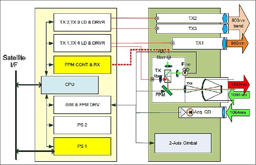
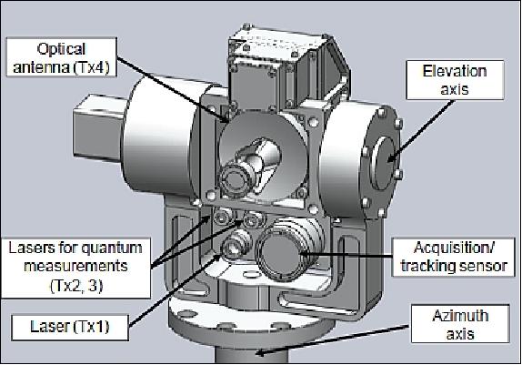
Integration of the SOTA-PFM has been completed. In the next phase, the following activities are to be verified:
• Overall performance test under ambient condition
• Environmental verification test
• Integrated vibration test mounted on the microsatellite STM (Structural and Thermal Model) to confirm and verify the interface between SOTA and the spacecraft.
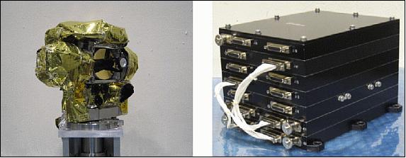
SOTA –PFM was manufactured and system level test campaigns were conducted. The environmental test result confirm that SOTA has sufficient environmental tolerances. The data transmission test through atmospheric turbulence reveals that the ATP (Acquisition Tracking and Pointing) functions of SOTA work well under such environments. The interface items between SOTA and the small satellite have been confirmed by fit tests with the satellite OBC. The next step in the SOTA development is an integrated test with the small satellite bus.
OGS (Optical Ground Station)
NICT (National Institute of Information and Communications Technology) constructed the OGS for the satellite laser communication experiment at HQs in Koganei, Tokyo. The core facility of the OGS is the Cassegrain reflector telescope with 1 meter aperture; the tracking and pointing performance is enough for LEO satellite support. The new OGS is dedicated for the SOTA/SOCRATES experiment. 24)
The primary mirror is a concave parabola while the secondary mirror is a hyperbola layout. The top ring with secondary mirror support structure is supported with a truss structure on the primary mirror cell. A bulk structure with primary mirror cell is mounted to the altitude-azimuth mount of the telescope system. To shield the system from wind and unwanted external light, a thin shield plate can be equipped on the truss and support structure. The focusing of the telescope system is executed by adjustment of distance between the primary mirror and secondary mirrors. The distance between the primary mirror cell and the top ring, which supports the secondary mirror assembly, is monitored by a laser displacement meter. The monitoring of the laser displacement meter provides accurate reproducibility of the telescope system focusing by the secondary mirror displacement.
The telescope system has one Cassegrain focus, two Nathmys foci, and two Coude foci, which is available with change of light path by flat mirrors. The telescope system has a collimator lens to provide the Coude focus far from telescope main optics. The design wavelengths are: 1.550 µm, 1.064 µm, and 0.532 µm, which is the wavelength of laser light sources for our application. The 0.532 µm is for the satellite laser ranging experiment. The Coude path is designed with no focus point on the light path, because the satellite laser ranging will use a pulse laser with large output power.
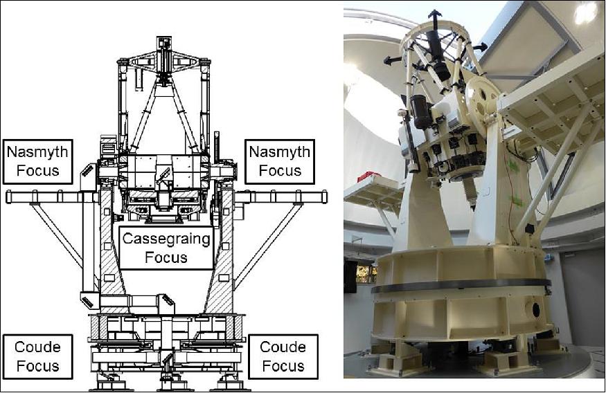
Optics system type | Classical Cassegrain reflector |
Available foci | Cassegrain, Nasmyth (two), Coude (two) |
Effective aperture of primary mirror | 1000 mm |
Focal length of primary mirror | 2000 mm |
Cassegrain focal ratio | F=12 |
Synthetic focal length | 12,000 mm |
Optical quality (wave front error) | 1/8 (at 633 nm pv) |
Strehl ratio | Larger than 0.9 |
Coating of mirror surface | Al+SiO |
Glass material of mirrors | Ceramic glass with low expansion/Astro sitall CO115M |
Altitude-azimuth mounting and control system:
The new OGS features a high performance altitude-azimuth style mount to point and track satellite in high accuracy and precision. In Table 8, the overview of the mechanical and dynamical specification and features are listed. The elevation axis has a through hole structure for the path of light reflected with flat mirror located after secondary mirror. The light path is used for the Nasmyth focus and the Coude focus. The collimator lens for the Coude path is located near the elevation axis.
Type of mount | Altitude-azimuth drive mount |
Tracking accuracy | 10 arcsec accuracy for LEO satellite support |
Pointing accuracy | 3 arcsec for a celestial object higher than 30º in elevation |
Image rotation | Available for the Cassegrain focus |
Through range | Azimuth: ±270º, Elevation: 10-88º |
Drive | Friction drive with direct drive motor |
Encoder | Optical incremental encoder |
The following options are available for the provision of tracking data:
1) TLE (Two Line Element) format
2) CPF (Consolidated Prediction Format)
3) AET (Azimuth-Elevation Table) for every second.
In AET mode, the tracking operation can be automatically started immediately after receiving the AET table via LAN or IP. The required tracking and pointing performance is confirmed in tracking test of the AJISAI or ENVISAT satellites and the SOCRATES/SOTA experiment. The Experimental Geodetic Satellite AJISAI is a bright satellite, reflecting sunlight with about 116 minutes orbital period and its orbit is determined precisely and opened. With a tracking test of AJISAI, the tracking performance test and adjustment including debugging is executed. Figure 22 is an example of tracking data in the SOCRATES/SOTA experiment operation. The graph shows that the tracking error of SOTA/SOCRATES tracking is less than five arc seconds. Furthermore, the small jitter during satellite tracking is a great advantage of this telescope. During the tracking test of the AJISAI satellite, we cannot find noticeable short period jitter or an abrupt jump of the satellite image which is often found during the visual observation of a LEO satellite or the Space Station by using a telescope for astronomical utility.
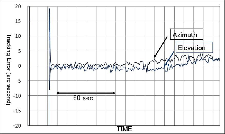
Experiment with SOTA (Small Optical Transponder)
The new OGS is operated for the ground segment laser communication experiment of SOTA/SOCRATES mission. The mission objective of the SOTA/SOCRATES mission is a fundamental experiment for laser communication between LEO and the ground. The aim of the experiment are demonstration of laser communication device in 1.5 µm wavelength in orbit, as well as fundamental experiment including propagation data collection of 1.5 µm laser through the terrestrial atmosphere.
Figure 23 illustrates the path of received beam on SOTA optics. The Tracking-QD (Quadrant Detector) for coarse pointing detects the 1 µm beacon from the OGS. SOTA has a high performance microprocessor unit with SH-4 (LCPU : Local CPU). The LCPU processes the QD's signal in real-time, gimbal of SOTA, and tracks the beacon within ±100 µradians. The FPM (Fine Pointing Mechanism) is driven by other QD's for fine tracking of the light path of RX-4 within ±20 µradians.
The SOTA-PFM has four optical transmitters of TX1, TX4, TX2 and TX3 which operate at 980 nm, 1550 nm and 800 nm band,respectively. The downlink lasers of Tx1 and Tx4 are modulated with a pseudo noise code or image data taken with camera onboard with 1Mbit/s or 10 Mbit/s downlink rate. The coding function with Reed-Solomon and LDGM is implemented for experiment to provide error correction. The wavelength of an uplink beam for acquisition and tracking is 1064 nm.
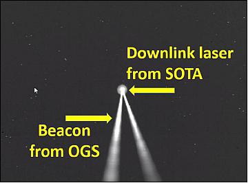
NICT provided also a small camera for Earth imaging based on the camera originally developed by the Kimura Laboratory of the Tokyo University of Science. The camera can produce uncompressed raw RGB data and JPEG images in several size options. The camera imagery will be used as a test content to be transferred as an optical data link experiment. Downloading the earth image taken by the onboard camera has been done successfully after the initial checkout phase of SOTA and the final implementation of new OGS. Figure 24 is an image taken with the camera onboard the OGS's telescope during one of the communication experiments with SOTA/SOCRATES. The 1 µm laser beam onboard the telescope works as a beacon to show the position of the OGS in the direction of SOTA. When SOTA acquires and tracks the beacon successfully, the transmission beam can be detected and received with the camera and receiver on OGS. In Figure 25, images of the transmitted laser beam from SOTA are captured as well as the beacon uplinked from OGS.

References
1) Morio Toyoshima, Takashi Sasaki, Hideki Takenaka, Yoshihisa Takayama, Yoshisada Koyama, "Verification Plan of Basic Quantum Key Distribution Experiments by Using a Small Satellite," Proceedings of the 28th ISTS (International Symposium on Space Technology and Science), Okinawa, Japan, June 5-12, 2011, paper: 2011-j-19
2) H. Takenaka, M. Toyoshima, Y. Takayama, Y. Koyama, M. Akioka, "Experiment plan for a small optical transponder onboard a 50 kg-class small satellite," Proceedings of ICSOS (International Conference on Space Optical Systems and Applications), Santa Monica, CA, USA, May 11-13, 2011
3) Yoshisada Koyama, Yoshihisa Takayama, Morio Toyoshima, Hideaki Takenaka, Maki Akioka, "Performance Characteristics of the Small Optical Transponder (SOTA) onboard Microsatellite," Proceedings of IAC 2011 (62nd International Astronautical Congress), Cape Town, South Africa, Oct. 3-7, 2011, paper: IAC-11- B2.2.9
4) Hideki Takenaka, Morio Toyoshima, Yozo Shoji, Yoshihisa Takayama, Yoshisada Koyama, Maki Akioka, "Evaluation of the optical communication system for Small Optical TrAnsponder (SOTA) based on the laboratory test," Proceedings of IAC 2011 (62nd International Astronautical Congress), Cape Town, South Africa, Oct. 3-7, 2011, paper: IAC-11.B2.2.10
5) "AES Satellite SOCRATES," AES, URL: http://www.aes.co.jp/product/pdf/socrates_hp_e.pdf
6) http://www.aes.co.jp/index.html
7) Kei-ichi Hirako, Takanobu Omoto, Hiroshi Tachihara, Moto Takai, Osamu Imaizumi, "Micro Earth Sensor with COTS parts for Commercial Air Conditioner," 10th IAA Symposium on Small Satellites for Earth Observation, Berlin, Germany, April 20-24, 2015, paper: IAA-B10-1202
8) "Launch of H-IIA Launch Vehicle No. 24," JAXA, MHI, March 14, 2014, URL: http://www.jaxa.jp/press/2014/03/20140314_h2af24_e.html
9) Toshinori Kuwahara, Kazaya Yoshida, Yuji Sakamoto, Yoshihiro Tomioka, Kazifumi Fukuda, Nobuo Sugimura, Junichi Kurihara, Yukihoro Takahashi, "Space Plug and Play Compatible Earth Observation Payload Instruments," Proceedings of the 9th IAA Symposium on Small Satellites for Earth Observation, Berlin, Germany, April 8-12, 2013, Paper: IAA-B9-1502, URL: http://media.dlr.de:8080/erez4/erez?cmd=get&src=os/IAA/archive9/Presentations/IAA-B9-1502.pdf
10) "World's First Demonstration of Space Quantum Communication Using a Microsatellite," NICT Press Release, July 11, 2017, URL: http://www.nict.go.jp/en/press/2017/07/11-1.html
11) Hideki Takenaka, Alberto Carrasco-Casado, Mikio Fujiwara, Mitsuo Kitamura, Masahide Sasaki, Morio Toyoshima, "Satellite-to-ground quantum-limited communication using a 50-kg-class micro-satellite," Nature Photonics (August issue, 2017), URL: http://www.nature.com/nphoton/index.html , DOI: 10.1038/nphoton.2017.107
12) Alberto Carrasco-Casado, Hideki Takenaka, Dimitar Kolev, Yasushi Munemasa, Hiroo Kunimori, Kenji Suzuki, Tetsuharu Fuse, Toshihiro Kubo-Oka, Maki Akioka, Yoshisada Koyama, Morio Toyoshima, "LEO-to-Ground Optical Communications using SOTA (Small Optical TrAnsponder) –Payload Verification Results and Experiments on Space Quantum Communications," Proceedings of the 67th IAC (International Astronautical Congress), Guadalajara, Mexico, Sept. 26-30, 2016, paper: IAC-16-B2.7
13) Information provided by Hideki Takenaka of NICT (National Institute of Information and Communications Technology), Tokyo, Japan.
14) Hideki Takenaka, Yoshisada Koyama, Dimitar Kolev, Maki Akioka, Naohiko Iwakiri, Hiroo Kunimori, Alberto Carrasco-Casado, Yasushi Munemasa, Eiji Okamoto, Morio Toyoshima, "In-orbit verification of small optical transponder (SOTA) –Evaluation of satellite-to-ground laser communication links," Proceedings of SPIE, Vol. 9739, 973903, 'Free-Space Laser Communication and Atmospheric Propagation XXVIII, edited by Hamid Hemmati, Don M. Boroson, San Francisco, CA, USA, Feb. 15-16, 2016, doi:10.1117/12.2214461
15) D.-H. Phung, E. Samain, N. Maurice, D. Albanesse, H. Mariey, M. Aimar, G. M. Lagarde, G. Artaud, J.-L. Issler, N. Vedrenne, M.-T. Velluet, M. Toyoshima, M. Akioka, D. Kolev, Y. Munemasa, H. Takenaka, N. Iwakiri, "Telecom and scintillation first data analysis for DOMINO: laser communication between SOTA, onboard SOCRATES satellite, and MEO optical ground station," Proceedings of SPIE, Vol. 9739, 973909, 'Free-Space Laser Communication and Atmospheric Propagation XXVIII' edited by Hamid Hemmati, Don M. Boroson , San Francisco, CA, USA, Feb. 15-16, 2016, doi:10.1117/12.2218524
16) Naohiko Iwakiri, Morio Toyoshima, "OOK Modulated Optical Satellite Communications System for CCSDS Standardization," Proceedings of the 30th ISTS (International Symposium on Space Technology and Science), Kobe-Hyogo, Japan, July 4-10, 2015, paper: 2015-j-16
17) "The Consultative Committee for Space Data Systems: TM Synchronization and Channel Coding," CCSDS 131.0-B-2, 2011
18) Yoshisada Koyama, Morio Toyoshima, Yoshihisa Takayama , Hideki Takenaka, Koichi Shiratama, Ichiro Mase, Osamu Kawamoto, "SOTA:Small Optical Transponder for Micro-Satellite," IEEE ICSOS (International Conference on Space Optical Systems and Applications), Santa Monica, CA, USA, May 11-13, 2011
19) Yoshihisa Takayama, Morio Toyoshima, Yoshisada Koyama, Hideki Takenaka, Maki Akioka, Koichi Shiratama, Ichiro Mase, Osamu Kawamoto, "Current development status of Small Optical TrAnsponder (SOTA) for satellite-ground laser communications," Proceedings of SPIE, 'Free-Space Laser Communication Technologies XXIV' Edited by Hamid Hemmati, Don M. Boroson, Volume 8246, San Francisco, CA, Jan. 21, 2012, pp. 824607-824607-7, doi:10.1117/12.913254
20) Yoshihisa Takayama, Yoshisada Koyama, Hideki Takenaka, Hiroo Kunimori, Morio Toyoshima, "Studies on candidate approaches for satellite-ground laser communications," Proceedings of the ICSOS (International Conference on Space Optical Systems and Application) 2012, Ajaccio, Corsica, France, October 9-12, 2012
21) Hideki Takenaka, Morio Toyoshima, Yoshihisa Takayama, Yoshisada Koyama, Maki Akioka, Eiji Okamoto, Takuma Kyo, "Study on Error Coding Program for Implementation in SOTA," Proceedings of the ICSOS (International Conference on Space Optical Systems and Application) 2012, Ajaccio, Corsica, France, October 9-12, 2012
22) Yoshisada Koyama, Yoshihisa Takayama, Maki Akioka, Hideki Takenaka, Yasushi Munemasa, Morio Toyoshima, "Completion of the Small Optical Transponder Development for satellite-ground laser communication demonstrations," AIAA International Communications Satellite Systems Conference (ICSSC), Florence, Italy, October 14-17, 2013, URL: http://www.kaconf.org/CD2013/papers/Ka_24/140.pdf
23) Naohiko Iwakiri, Yoshihisa Takayama, Dirk Giggenbach, "Explanatory Document for Standardization Work - Direct Optical Low-Earth Orbit Satellite Downlinks with on-off-keying Modulation," CCSDS, Oct. 1, 2014, URL: http://cwe.ccsds.org/sls/docs/SLS-OPT/Monthly%20Telecons/20141001%20-%20October%201%20VITS/20141001-OLEODL-CCSDS_DLR-NICT.pdf
24) Maki Akioka, Hideki Takenaka, Morio Toyoshima, Yoshisada Koyama, Yoshihisa Takayama, "The NICT's New OGS for Satellite Laser Communication and SOTA/Socrates experiment," Proceedings of the 14th International Conference on Space Operations (SpaceOps 2016), Daejeon, Korea, May 16-20, 2016, URL: http://arc.aiaa.org/doi/pdf/10.2514/6.2016-2376
The information compiled and edited in this article was provided by Herbert J. Kramer from his documentation of: "Observation of the Earth and Its Environment: Survey of Missions and Sensors" (Springer Verlag) as well as many other sources after the publication of the 4th edition in 2002. - Comments and corrections to this article are always welcome for further updates (eoportal@symbios.space).
Spacecraft Launch Mission Status Experiments Optical Ground Station References Back to Top