SPIDER (Segmented Planar Imaging Detector for ElectroOptical Reconnaissance)
EO
Quick facts
Overview
| Mission type | EO |
SPIDER (Segmented Planar Imaging Detector for ElectroOptical Reconnaissance)
Mission Background Concept Design References
The Lockheed Martin Advanced Technology Center (LM ATC) in Palo Alta, CA, and the University of California at Davis (UC Davis) are developing an electrooptical (EO) imaging sensor called SPIDER that seeks to provide a 10 x to 100 x SWaP (Size, Weight, and Power) reduction alternative to the traditional bulky optical telescope and focal-plane detector array. The substantial reductions in SWaP would reduce cost and/or provide higher resolution by enabling a larger-aperture imager in a constrained volume. 1) 2) 3)
Our SPIDER imager replaces the traditional optical telescope and digital focal plane detector array with a densely packed interferometer array based on emerging PIC (Photonic Integrated Circuit) technologies that samples the object being imaged in the Fourier domain (i.e., spatial frequency domain), and then reconstructs an image. Our approach replaces the large optics and structures required by a conventional telescope with PICs that are accommodated by standard lithographic fabrication techniques (e.g., CMOS (Complementary Metal-Oxide-Semiconductor) fabrication).
The standard EO payload integration and test process that involves precision alignment and test of optical components to form a diffraction limited telescope is, therefore, replaced by in-process integration and test as part of the PIC fabrication, which substantially reduces associated schedule and cost. We describe the photonic integrated circuit design and the testbed used to create the first images of extended scenes. We summarize the image reconstruction steps and present the final images. We also describe our next generation PIC design for a larger (16 x area, 4 x field of view) image.
Background
Since Galileo (1564-1642) first started gazing at the stars atop a mountain in Italy, to modern-day astronomers who can see billions of miles into space, the general design of a telescope has pretty much remained the same.
In fact, even if you're looking at the stars using only the light-sensitive cells in your eyes, the image-forming process works the same way. Both methods collect light from an object and then reflect that light to form an image. Just like observatories and science classrooms use telescopes to gaze up, satellites use telescopes, too. That's how we get map images and weather forecasts, and you may recognize the most famous of these eyes in space, the incredible Hubble Space Telescope.
From space, the need for higher-resolution imaging to resolve far away objects requires bigger and bigger telescopes to the point where the size, weight and power of the telescope can completely dominate a system. Plus, it's also really expensive to put big, heavy objects in space.
"We can only scale the size and weight of telescopes so much before it becomes impractical to launch them into orbit and beyond," said Danielle Wuchenich, senior research scientist at Lockheed Martin's Advanced Technology Center in Palo Alto, California. "Besides, the way our eye works is not the only way to process images from the world around us."
In order to shed pounds on future telescopes, scientists at Lockheed Martin are taking a new look at how to process imagery by using a technique called interferometry. Interferometry takes in what you're seeing, photons, using a thin array of tiny lenses that replaces the large, bulky mirrors or lenses in traditional telescopes. Large-scale interferometer arrays, located in observatories around the world, are used to collect data over large periods of time to form ultra-high-resolution images of objects in space.
SPIDER flips that concept, staring instead from space, and trading person-sized telescopes and complex combining optics for hundreds or thousands of tiny lenses that feed silicon-chip photonic integrated circuits (PICs) to combine the light in pairs to form interference fringes.
The amplitude and phase of the fringes are measured and used to construct a digital image. This provides an increase in resolution while maintaining a thin disk. It's a revolutionary concept analogous to the idea that helped replace your bulky old television with a thin display that can hang on your living room wall. It's also how Lockheed Martin's imaging technology, called SPIDER, could reduce the size, weight and power needs for telescopes by 10 to 100 times. This concept could make a big difference for commercial and government satellites alike.
"What's new is the ability to build interferometer arrays that have the same number of channels as a digital camera," said Alan Duncan, senior fellow at Lockheed Martin. "They can take a snapshot, process it and there's your image. It's basically treating interferometer arrays like a point-and-shoot camera."
SPIDER's photonic integrated circuits do not require complex, precision alignment of large lenses and mirrors. That means less risk on orbit. And its many eyes can be rearranged into various configurations, which could offer flexible placement options on its host. Telescopes have always been cylindrical, but SPIDER could begin a new era of different thin-disk shapes staring in the sky, from squares to hexagons and even conformal concepts.
Duncan's team, which includes Wuchenich, is developing this capability in the heart of Silicon Valley at the ATC (Advanced Technology Center). This is also the home of the Optical Payload Center of Excellence, which brings together the collective expertise of Lockheed Martin's space observation professionals. Alan and other scientists form the research base of the center so that one day, developmental technologies like SPIDER could be an option on production spacecraft.
Developed with funding from DARPA (Defense Advanced Research Projects Agency), the SPIDER design today is still in its early stages. It uses just several lenses and their associated PICs developed by Lockheed Martin's research partners at University of California, Davis. Despite the technology's advances, Duncan predicts SPIDER's capabilities could still be five to ten years away from being fully matured.
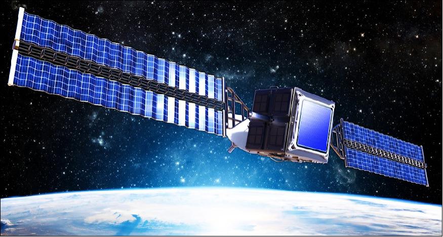
However, the team envisions a future where a telescope could be scaled up to serve in a similar capacity as telescopes that are currently photographing the planet, and at a fraction of the cost. In fact, SPIDER could even be able to operate on a spacecraft as a hosted payload, where it could simply be mounted to the side of a vehicle with minimal size, weight and power impact.
"SPIDER has the potential to enable exciting discoveries by putting high-resolution imaging systems within outer planet system orbits such as Saturn and Jupiter," said Duncan. "The ability to reduce size, weight and power could significantly change the game. With 10 to 100 times the resolution of a comparable-weight traditional telescope, imagine what you could discover."
SPIDER Concept Design
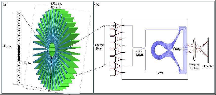
The SPIDER imager consists of a multitude of direct-detection white-light interferometers on a PIC which generates interference fringes. The measured complex visibility (phase and amplitude) of the fringes corresponds to a Fourier component of the object being imaged through the Van Cittert-Zernike theorem. A 2D Fourier fill of the scene (object) being imaged is attained by collecting data for multiple 1D interferometer arrays with several orientations. To achieve azimuthal sampling, the arrays are arranged in a radial blade pattern, pictured in Figure 1(a).
The imager design is composed of 37 1D arrays with lenslets coupling light from an extended scene into waveguides in the PIC, where interferometric beam combination occurs. Dense radial sampling is achieved by making measurements at various optical wavelengths or spectral bands for each of the baselines in the individual 1D interferometer arrays. Data collected for each baseline and spectral channel correspond to angular spatial frequencies B/λ where B is the baseline, or distance between lenslet pairs and λ is the wavelength of light. Therefore, higher spatial frequency information about the object will be captured by longer baselines and shorter wavelengths. The spatial resolution of SPIDER is determined by its effective aperture size which is equal to the length of the maximum baseline, Bmax. Measuring 12 baseline pairs on each PIC of the imager provides the 2D Fourier transform of the object, effectively mapping the 2D Fourier plane of the scene.

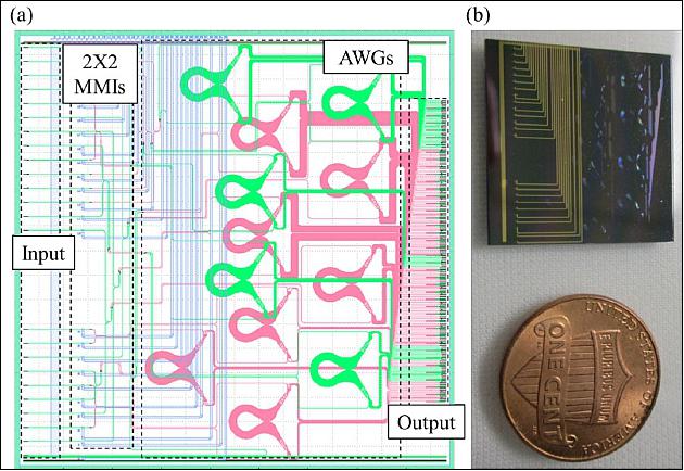
The main component of the electrooptical sensor is the planar photonic integrated circuit design for the 1D interferometer arrays. Two past generations of PICs were developed and characterized . 5) 6) The newest PIC design is discussed here and was introduced in a former work. 7) We use the third generation SPIDER PIC which is 22 x 22 mm in size, providing an average of 6 dB insertion loss and -15 dB throughput attenuation. The PIC's lithographic layout is pictured in Figure 2(a) along with a picture in Figure 2(b). It contains 24 input waveguides that are paired up to form 12 baselines using 2 x 2 MMI (Multi-Mode Interferometer) beam combiners. Light from each of the MMI output ports is then spectrally split using AWGs (Arrayed Waveguide Gratings), which allow broadband operation and provide increased spatial frequency coverage. The AWGs for each baseline are identical and provide a maximum of 18 spectral channels ranging from 1223 nm to 1586 nm and uniformly spaced in wavenumber. All 18 spectral channels are used for the longest baseline, while fewer are needed for the short baselines. The total number of output ports for each PIC is 206.

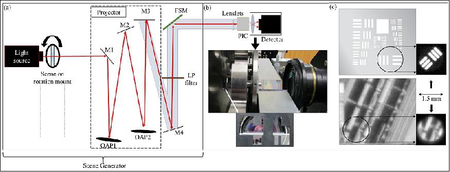
An in-lab optical testbed was implemented to test the PIC's ability to create images of extended scenes. The testbed is pictured in Figure 3. It includes a back-illuminated scene and a projector, which effectively places the scene in the far field of the PIC. Light from the scene is then coupled through the lenslets, into the PIC interferometers and to the detector which records the interference fringes. The PIC output ports are actually imaged by a lens onto a focal plane array for the detection. While the PIC includes thermoelectric phase modulators that enable estimation of the complex (amplitude and phase) fringe visibility through temporal fringe scanning, the PIC was not actually wire bonded. Instead, we used a FSM (Fast-Steering Mirror) driven by a sinusoidal voltage signal to scan through the fringes. The bottom of Figure 3(b) displays a three-row mask placed in front of the lenslets which is used to block various lenslets for characterization of the optical throughput for individual beam paths (without interference). This is necessary for estimating the normalized fringe visibility, which is a measure of the complex degree of coherence and independent of the relative beam intensities for each baseline.
The images chosen for the scene include a USAF (U.S. Air Force) resolution test chart (group 2 element 1), and (2) a scene of a train yard, shown in Figure 3(c). As described previously, we used a 1.5 mm diameter aperture mask over both scenes to match the scene width to the system field of view (Ref. 7).

SPIDER Processed Images
Imaging demonstrations were performed with two scenes: a set of tri-bars from a USAF resolution target and a grayscale aerial-photograph of a train yard. Both scenes were chrome-on-glass transparencies that were masked down to the PIC FOV with a 1.5 mm diameter circular aperture. For each scene, data was collected for scene orientation angles 0-180 degrees in 5- or 10 degree increments. Data does not need to be collected over a full range of 360 degrees, because the Fourier transform of a real-valued intensity object has Hermitian symmetry.
Figure 4(a) shows several images for the USAF bar target. The first image is a synthetic digital model of the scene, while the second is a simulated image, created by computing noise-free Fourier samples of the scene with the same sampling as the experimental data and using an inverse FFT (Fast Fourier Transform) reconstruction algorithm. This simulated image gives an indication of the image quality expected from the experiment. The third image is an initial FFT-based reconstructed image of the bar chart. The features of the bar target are noticeably blurred compared with its simulation. We believe this is caused from wobble in the rotation stage used to rotate the scene between each data set. This was investigated by comparing the experimental data for each scene orientation with the synthetic data used to generate the simulated image. Translation of the scene with rotation angle (the effect of stage wobble) can be detected through this comparison as a linear phase error (vs. radial spatial frequency) that varies systematically with rotation angle. Additionally, the linear phase errors can be removed from the experimental data to reconstruct the final FFT-based image, which is shown on the right of Figure 4(a). Note that stage wobble would not be an issue in a SPIDER system based on a 2D array of PICs, as shown in Figure 1(a) within a rigid mount.
Figure 4(b) shows similar image results for the scene object of a train yard, with the exception that the last image is the result of an iterative image reconstruction algorithm that incorporates penalty metrics for nonnegativity and finite scene support as well as a total-variation metric for regularization. These terms incorporate a priori information about the scene and help mitigate the impacts of sparse Fourier sampling in the experiment. While there are some artifacts, the final reconstruction matches the truth object shown on the left of Figure 4(b) fairly well. Note that the truth object was obtained by viewing the actual slide transparency with a microscope equipped with a camera. The quality of the final image for both targets authenticates SPIDER's imaging demo as a success.

In summary, the extended scene imaging demonstration for SPIDER gave results allowing us to be confident in the system. SPIDER's full design consists of a 2D array of multiple PICs, but in this demo we used an individual PIC to successfully demonstrate the system's imaging capability via rotation of the scene. A wobble in the scene rotation stage introduced phase errors in the data collected for the imaging demos, but this would not be a problem in a final system that does not rely on scene rotation for data collection.
Roughly 30 percent of the output waveguides had no measurable interference fringe, so these needed to be identified for image characterization. Over time the PIC design has been modified to reduce the number of waveguide crossings to reduce on-chip losses and cross-talk between baselines. Minimizing the number of crossings reduces the on-chip losses and cross-talk insertion loss. We continue to work to reduce the throughput losses in the PIC and expect a fourth-generation PIC throughput attenuation to drop by 5 dB, giving us an improved throughput loss of 10 dB including coupling efficiency.
The optical testbed and image reconstruction experiment proved that the SPIDER system would work, but we continue to research advanced state-of-the-art PIC capabilities. The future of SPIDER includes more experimentation and work on improvement of the PIC technology and optimization of the system architecture which would both reduce SWaP and improve image quality. A reduction in SWaP is to be achieved by increasing system complexity and system integration. We plan on designs with longer baselines for higher resolution, and more baselines for dense Fourier sampling. With a maximum system baseline of 100 mm we can obtain images 4 x in size or 200 x 200 image "pixels." We also plan to incorporate higher-density integration using multiple PIC combinations, along with detectors on the PIC. We are also exploring real-time image processing approaches.

1) Katherine Badham, Alan Duncan, Richard L. Kendrick, Danielle Wuchenich, Chad Ogden, Guy Chriqui, Samuel T. Thurman, Tiehui Su, Weicheng Lai, Jaeyi Chun, Siwei Li, Guangyao Liu, S. J. B. Yoo, "Testbed experiment for SPIDER: A photonic integrated circuit-based interferometric imaging system," AMOS (Advanced Maui Optical and Space Surveillance Technologies) Conference, Wailea, Hawaii, September 18-22, 2017, URL: https://amostech.com/TechnicalPapers/2017/Poster/Badham.pdf
2) "Shrinking the Telescope — SPIDER (Segmented Planar Imaging Detector for Electro-optical Reconnaissance)," Lockheed Martin, URL: https://lockheedmartin.com/content/dam/lockheed-martin/eo/documents/webt/spider-infographic.pdf
3) S. J. Ben Yoo, Ryan P. Scott, Alan Duncan, "Low-Mass Planar Photonic Imaging Sensor," 2014 NIAC (NASA Innovative Advanced Concepts) Symposium, at Stanford University in Palo Alto, CA, Feb. 4-6, 2014, URL: https://www.nasa.gov/sites/default/files/files/Ben
Yoo_LowMassPlanarPhotonicImagingSensor.pdf
4) Lockheed Martin, 19 January 2016, URL: https://lockheedmartin.com/us
innovations/011916-webt-spider.html
5) Alan L. Duncan, Richard L. Kendrick, Chad Ogden, Danielle Wuchenich, Samuel T. Thurman, S. J. S. B. Yoo, Tiehui Su, Shibnath Pathak, Roberto Proietti, "SPIDER: Next Generation Chip Scale Imaging Sensor", Proceedings of the Advanced Maui Optical and Space Surveillance Technologies Conference, Wailea, Hawaii, September 15-18, 2014, URL: https://amostech.com/TechnicalPapers
/2015/Optical_Systems/Duncan.pdf
6) Alan L. Duncan, Richard L. Kendrick, Chad Ogden, Danielle Wuchenich, Samuel T. Thurman, Tiehui Su, Weicheng Lai, Jaeyi Chun, Siwei Li, Guangyao Liu, S. J. B. Yoo, "SPIDER: Next Generation Chip Scale Imaging Sensor Update", Proceedings of the AMOS (Advanced Maui Optical and Space Surveillance Technologies) Conference, Wailea, Hawaii, September 20-23, 2016. URL: https://amostech.com/TechnicalPapers/2016
/Adaptive-Optics_Imaging/Duncan.pdf
7) "Photonic integrated circuit-based imaging system for SPIDER" Badham, et al, The Pacific Rim Conference on Lasers and Electro-Optics, Singapore, July 31-Aug. 4, 2017
The information compiled and edited in this article was provided by Herbert J. Kramer from his documentation of: "Observation of the Earth and Its Environment: Survey of Missions and Sensors" (Springer Verlag) as well as many other sources after the publication of the 4th edition in 2002. - Comments and corrections to this article are always welcome for further updates (eoportal@symbios.space)