SPROUT (Space Research on Unique Technology)
EO
Operational (nominal)
Nihon University
Quick facts
Overview
| Mission type | EO |
| Agency | Nihon University |
| Mission status | Operational (nominal) |
| Launch date | 24 May 2014 |
| CEOS EO Handbook | See SPROUT (Space Research on Unique Technology) summary |
SPROUT (Space Research on Unique Technology)
SPROUT is a nanosatellite demonstration mission of Nihon University, Tokyo, Japan. The prime objective is to test the deployment of a combined membrane structure (1.5m-sided triangular membrane supported with two space-inflatable tubes) and 3-axes attitude control technology. A further goal of the mission is to perform the demonstration experiment of the ADCS (Attitude Determination and Control Subsystem) of a nanosatellite with a large membrane structure by using in-house manufactured magnetic torquers and COTS sensors.
The SPROUT mission is comprised of two missions, namely the engineering mission and the outreach mission. The goal of the engineering mission is the introduction of cutting-edge experiments, while the outreach mission aims to promote public interest in space development and operations. 1) 2)
Engineering Mission:
• Deployment demonstration of the combined membrane structure (minimum success is expected to be achieved within four months after the launch)
• Demonstration of design methods of the combined membrane structure (full success is expected to be achieved after about six months)
• Demonstration of ADCS technology for nanosatellites (extra success is expected to be achieved after about nine months)
• Prediction of the orbit descent rate of the nanosatellite with large membrane (extra success is expected to occur within five years).
Outreach Mission:
• Satellite operation will be granted to the amateur radio community (full success is expected within six months)
• Promotion of regional exchange on science and technology
• Provision of information on project activities and share of Earth imagery observed by the on-board camera.
Spacecraft
SPROUT is a nanosatellite of size 213 mm x 213 mm x 210 mm with a mass of ~ 7.1 kg. The spacecraft consists of the rigid main body, two inflatable tubes, a thin membrane, a storage box, and a gas pipe structure. The inflatable deployment structure is described in the “experiment complement”. 3)
ADCS (Attitude Determination and Control Subsystem): The project designed and developed a flexible and customizable system that consists of small, light, and cheap COTS (Commercial-Off-The-Shelf) components, suitable to mount on a nanosatellite. SPROUT uses a 3-axis magnetometer, three gyro sensors, six sun sensors, and four temperature sensors for the attitude determination, and three magnetic torquers for actuation. The sun sensors and the magnetic torquers were manufactured in-house. Figure 2 is a block diagram of the SPROUT subsystems with emphasis on ADCS.
The relation between ADCS and the other onboard subsystems is as follows: ADCS is activated by receiving a command from the C&DH (Command and Data Handling Subsystem). SPROUT has two C&DHs: C&DH1 handles the command and data for the engineering mission system, while C&DH2 handles the command and data for the outreach mission system.
The SPROUT project uses the following grouping and terminology to describe the onboard sensors:
• SG1 (Sensor Group 1): This group involves housekeeping sensors such as solar cell current and voltage, battery voltage.
• SG2 refers to the attitude determination sensors, i.e. the gyros, sun sensors, magnetic sensors, thermal sensors, etc.
• The SG3 deals with the sensors for the combined membrane structure, i.e. the piezo sensors and the pressure sensors.
Each subsystem receives the sensor data necessary for the subsystem. For example, ADCS gets SG2 data and runs the attitude control code. Each subsystem, including ADCS, has the satellite time to relate the sensor data and the time. The RTC (Real Time Clock Subsystem) manages the time synchronization of each subsystem.
EPS (Electric Power Subsystem): EPS controls the power generated by the solar cells, the battery charging, and the power supply to all subsystems with a circuit voltage of 3.7-5 V.
TCS (Thermal Control Subsystem): TCS employs passive and active control functions to keep the spacecraft temperatures within limits.
RF communications: This subsystem consists of a dual FMR (Fflight Management Receiver) subsystem which receives and process uplink data from the ground station. A CW (Continuous Wave) line transmits the housekeeping data in Morse code. The communication is separated for mission use and the ham radio mission use. There are a total of 4 communication links, an uplink and downlink for the engineering mission as well as an uplink and downlink line for the ham radio service.
The engineering data are transmitted in VHF (140 MHz) in uplink at a data rate of 1.2 kbit/s (FM/AFSK modulation); the downlink is transmitted at a frequency of 40 MHz (CW beacon) at rates of 1.2 kbit/s (FM/AFSK) and 9.6 kbit/s (FM/GMSK). The transmission rates for the ham radio community are 1.2 kbit/s (FM/AFSK) in uplink and in downlink.
For FRM, the FRM1 subsystem handles the data for the engineering mission, while the FRM2 works for outreach mission.
Camera module subsystem: SPROUT features three onboard cameras:
• CAM1 and CAM2 are dedicated to the engineering mission -in particular to take imagery of the combined membrane structure during and after deployment.
• The CAM3 system is dedicated for the outreach mission which is the satellite operation by the ham radio operators - it may be used to take imagery of the Earth. ADCS is needed for the pointing of CAM3 observations to a particular target. Hence, ADCS manages also the shutter of CAM3.
The imagery format is 640 x 480 pixels in size. All images are transmitted either in full size, or in thumbnail size (320 x 240, 160 x 120, ....) or in SSTV (Slow Scan Television) mode of the Scotti1 format.
Launch
The SPROUT nanosatellite was launched as a secondary payload on May, 24 2014 (03:05 UTC) on a H-IIA 202 vehicle from TNSC (Tanegashima Space Center), Japan. The launch provider was MHI (Mitsubishi Heavy Industries, Ltd.).The primary mission was ALOS-2 (Daichi-2) of JAXA. 4)
Orbit: Sun-synchronous near-circular orbit, altitude = 628 km, inclination = 97.9º, period = 97.4 minutes, LSDN (Local Sun time on Descending Node) = 12:00 hours ± 15 min.
The secondary missions manifested on the ALOS-2 mission by JAXA were: 5)
• Rising-2, a cooperative microsatellite (43 kg) project of Tohoku University (Sendai) and Hokkaido University, Sapporo, Japan.
• UNIFORM-1 (University International Formation Mission-1), a microsatellite (~50 kg) of Wakayama University, Wakayama, Japan.
• SOCRATES (Space Optical Communications Research Advanced Technology Satellite), a microsatellite (~ 50 kg) mission of NICT (National Institute of Information and Communications Technology), Koganei, Japan.
• SPROUT (Space Research on Unique Technology), a nanosatellite of ~7.1 kg of Nihon University.
Experiment Complement (Deployment System)
The objective of the demonstration deployment system is to increase drag at the orbital altitude to comply with the IADC (Inter-Agency Space Debris Coordination Committee) regulations for space debris, resulting in a faster reentry of the spacecraft. The IADC guideline calls for limiting the lifetimes of such debris in LEO to 25 years at the end of the mission.
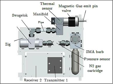
The gas pipe structure consists of the gas cartridge, gas regulator and two SMA (Shape Memory Alloy) valves (Ref. 2).
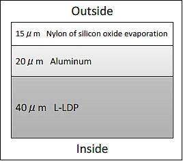
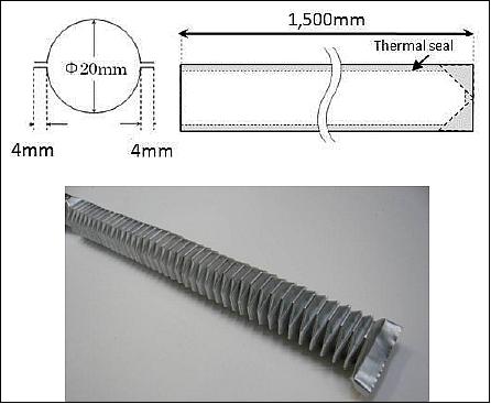
The inflatable tube is made of thermal fusion bonding at both ends. A material composition of the aluminum laminate film is shown in Figure 9. The aluminum laminate film has a thickness of 75 µm . It consists of the nylon of silicon oxide evaporation (15 µm ), aluminum (20 µm ), L-LDP (40 µm ). The extended inflatable tube length is about 1,500 mm (before deployment, the tube length is ~10 mm), and the tube bore diameter is about 20 mm. The overview of the inflatable tube is shown in Figure 10.
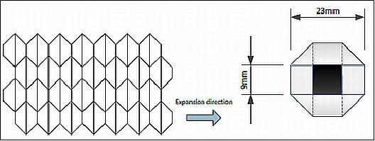
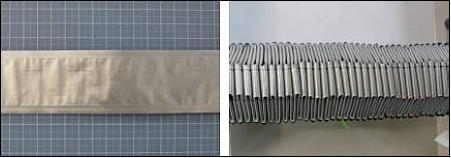
The inflatable tube folding method is “Octagon-ori”. The folding pattern and the dimension of the “octagon-ori” tube are shown in Figures 11 and 12. The flow passage area of the tube is 81 mm2 . The project uses a slender bar made of expanded polypropylene to assist in the folding of the tube. The assisting tool of the expanded polypropylene is shown in Figure 13.
Gas Pipe Structure: The gas pipe structure and cartridge are shown in Figures 14. Nitrogen gas is used for the deployment sequence which is stored in a cartridge of 20 ml volume; the cartridge is a COTS item of NTG (Nippon Tansan Gas).
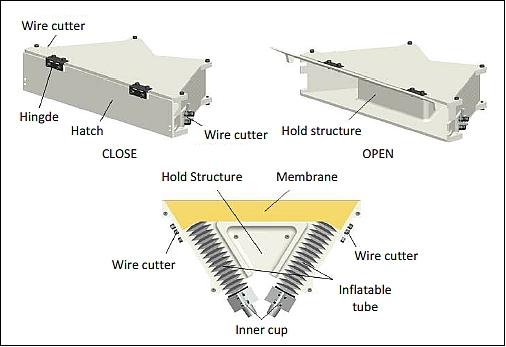
Storage box: The storage box of the inflatable tubes and the membrane is shown in Figures 15 and 17.
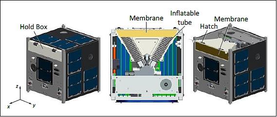
Deployment Sequence
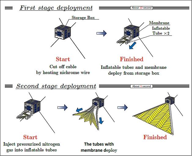
The deployment sequence of the combined membrane system is as follows (Figure 17).
1) Prior to launch, the inflatable tubes and the membrane are placed into the hold structure.
2) After deployment of SPROUT, an electric current flows through the SMA valves on ground command - resulting in the opening of the gas cartridge.
3) The hatch of the hold structure is opened. Inflatable tubes and membrane extension slowly from storage box (first stage deployment).
4) The inflatable tubes with membrane will deploy by injecting nitrogen gas into the inflatable tubes (second stage deployment).
5) After full system deployment, the remaining nitrogen gas is emitted to the outside.
Camera observations of the deployment sequence: The deployment sequence will be observed with two cameras to obtain stereo imagery from two locations on the nanosatellite. This will permit a 3D reconstruction of the deployment shape of the membrane. The result will be compared and analyzed to the imagery obtained in the ground test runs.
1) Atsushi Tanaka, Masahiko Yamazaki, Yasuyuki Miyazaki, “Attitude Determination and Control of SPROUT,” Proceedings of the 29th ISTS (International Symposium on Space Technology and Science), Nagoya-Aichi, Japan, June 2-8, 2013, paper: 2013-f-28
2) Shingo Shimazaki, Ryo Murata, Masahiko Yamazaki, Yasuyuki Miyazaki, “Deployment Mission of Inflatable Membrane Structure of Nano-Satellite SPROUT,” Proceedings of the 29th ISTS (International Symposium on Space Technology and Science), Nagoya-Aichi, Japan, June 2-8, 2013, paper: 2013-f-41
3) http://sat.aero.cst.nihon-u.ac.jp/sprout-e/1-System-e.html
4) “Launch of H-IIA Launch Vehicle No. 24,” JAXA, MHI, March 14, 2014, URL: http://www.jaxa.jp/press/2014/03/20140314_h2af24_e.html
5) Toshinori Kuwahara, Kazaya Yoshida, Yuji Sakamoto, Yoshihiro Tomioka, Kazifumi Fukuda, Nobuo Sugimura, Junichi Kurihara, Yukihoro Takahashi, “Space Plug and Play Compatible Earth Observation Payload Instruments,” Proceedings of the 9th IAA Symposium on Small Satellites for Earth Observation, Berlin, Germany, April 8-12, 2013, Paper: IAA-B9-1502, URL: http://media.dlr.de:8080/erez4/erez?cmd=get&src=os/IAA/archive9/Presentations/IAA-B9-1502.pdf
The information compiled and edited in this article was provided by Herbert J. Kramer from his documentation of: ”Observation of the Earth and Its Environment: Survey of Missions and Sensors” (Springer Verlag) as well as many other sources after the publication of the 4th edition in 2002. - Comments and corrections to this article are always welcome for further updates (eoportal@symbios.space)