SSOT (Sistema Satelital para la Observación de la Tierra) / FASat-C (Fuerza Aerea Satellite - Charlie)
EO
Ocean colour instruments
Ocean
High resolution optical imagers
Quick facts
Overview
| Mission type | EO |
| Agency | ACE |
| Mission status | Operational (nominal) |
| Launch date | 17 Dec 2011 |
| Measurement domain | Ocean, Land |
| Measurement category | Vegetation, Landscape topography, Ice sheet topography |
| Measurement detailed | Land surface imagery, Land cover, Land surface topography, Sea level, Sea-ice sheet topography, Ice sheet topography, Visibility, Mineral Type, Vegetation Canopy (height), Water vapour imagery, Vegetation Canopy (cover), Lake Area |
| Instruments | Imager, High Resolution Optical Sensor |
| Instrument type | Ocean colour instruments, High resolution optical imagers, Other, Communications, Data collection, Imaging microwave radars |
| CEOS EO Handbook | See SSOT (Sistema Satelital para la Observación de la Tierra) / FASat-C (Fuerza Aerea Satellite - Charlie) summary |
SSOT (Sistema Satelital para la Observación de la Tierra) / FASat-C (Fuerza Aerea Satellite - Charlie)
Overview Spacecraft Launch Mission Status Sensor Complement References
SSOT is an optical high-resolution microsatellite imaging mission of ACE (Agencia Chilena del Espacio - Chilean Space Agency) and the Chilean Air Force (FACh = Fuerza Aerea de Chile), Santiago, Chile. In August 2008, the government of Chile signed a contract with EADS Astrium SAS for the development of the SSOT system. The SSOT program also includes the development and setting up of a ground control segment and image processing facilities enabling the satellites to be directly operated and controlled from Chile by the Chilean authorities. The cooperation agreement makes provision for Chilean engineers to work alongside the Astrium development team. They will be given intensive training in space technology and will participate directly in SSOT project development. 1) 2) 3)
The contract with EADS Astrium represents a partnership solution for Chile in the field of Earth observation. The SSOT program follows in the wake of the FormoSat-2 satellite of Taiwan, which was launched on May 20, 2004, the South Korean KOMPSAT-2 and COMS satellites, the THEOS program developed for Thailand, which was launched on October 1, 2008, and the two AlSat-2 satellites, which are currently being built for the government of Algeria.
The SSOT mission will enable Chile to obtain high quality imagery for use in a wide variety of applications both in the defense and civil domains: cartography; agricultural management; forestry; water, mineral and oil resources; crop protection; natural disaster response; urban planning, etc.
In Chile, SSOT is also known as FASat Charlie as in the FASat Bravo (Fuerza Aerea Satellite - Bravo), a microsatellite mission of FACh, which was launched on July 10, 1998.
Spacecraft
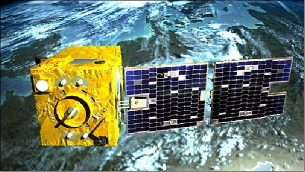
SSOT represents the third Earth observation satellite system from the AstroSat-100 family which is based on the Myriade platform of CNES. CNES signed partnership agreements with AAS (Alcatel Alenia Space) and EADS/Astrium SAS which permits them to use the Myriade bus design and products for their own applications/missions (defense, commercial market, etc.). EADS/Astrium refers to its customized Myriade platform version as AstroSat-100, capable of accommodating a payload of up to 50 kg and providing up to 50 W DC power.
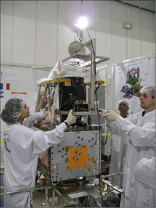
The SSOT spacecraft bus is of AlSat-2 heritage. The spacecraft structure is an aluminum box of size: 60 cm x 60 cm x 100 cm. Figure 2 shows the platform mechanical accommodation; all 4 panels of the structure fold out during integration, allowing easy access to all equipment during platform integration. This accommodation allows a good level of flexibility with respect to the payload size.
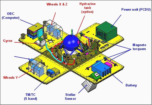
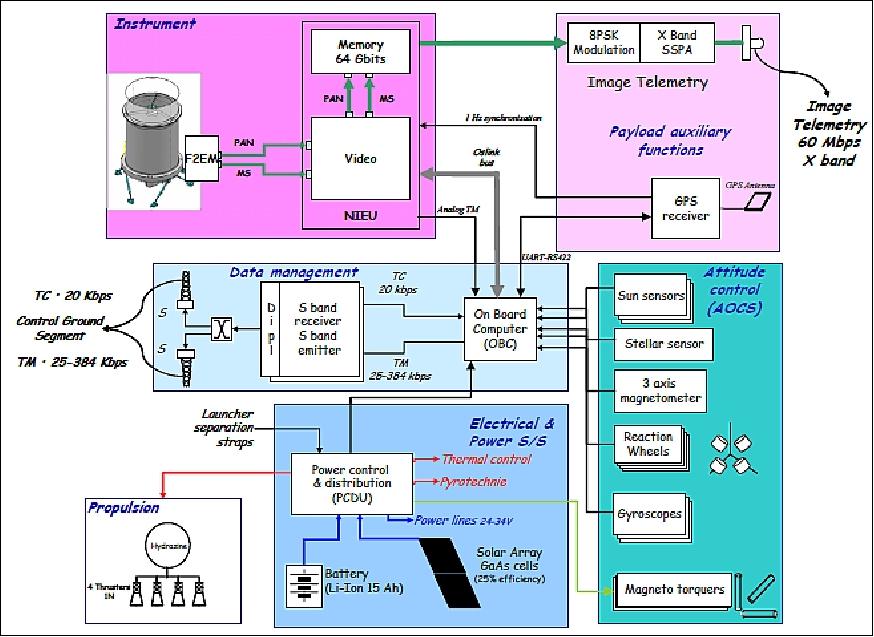
SSOT is 3-axis stabilized. Attitude sensing is provided by 3 sun sensors, a star sensor, a magnetometer, and an IRU (Inertial Measurement Unit); actuation is provided by 4 reaction wheels (each of 0.12 Nms) and magnetorquers. A GPS receiver is used for onboard location and time services. The spacecraft has a body-pointing capability of ±30º in cross-track.
The EPS (Electric Power Subsystem) features an AsGa solar array providing a power of 180 W (EOL). In addition, there is a Li-ion battery of 15 Ah capacity. - A T805 serves as OBC (Onboard Computer). A hydrazine propulsion subsystem (N2H4, ΔV = 70 m/s) is being used for on-orbit maintenance. The spacecraft has a mass of 117 kg. The design life is 5 years.
RF communications: SSOT features an onboard SSR (Solid-State Recorder) of 64 Gbit capacity. Communications are provided in X-band with a downlink rate of 60 Mbit/s. For TT&C support, 2 S-band transceivers are utilized (CCSDS, 20 kbit/s TC, 25-384 kbit/s TM).
Spacecraft structure | Aluminum bus structure, Size: 60 cm x 60 cm x 100 cm |
AOCS (Attitude & Orbit Control Subsystem) | - Magnetic autonomous acquisition |
EPS (Electric Power Subsystem) | - Power generated by one deployable solar array (GaAs; 180 W EOL) |
On-board data handling | - On-board computer (T805, 1 Gbit DRAM/EDAC, 8 Mbit Flash EEPROM) |
Payload data management | - X band downlink: 60 Mbit/s |
Performance | - Spacecraft launch mass: 117 kg |
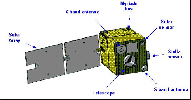
Figure 4 shows the AstroSat-100 satellite electrical architecture embedding the NAOMI optical payload.

Launch
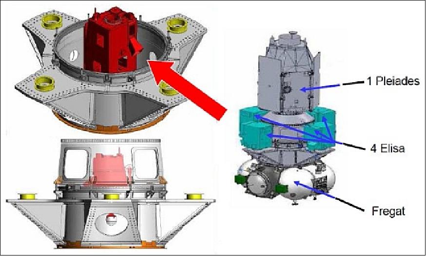
SSOT was launched on December 17, 2011 as a secondary payload on a Soyuz-STA/Fregat launcher from Kourou (launch provider: Arianespace, flight VS02 = Vehicle Soyuz 02 mission). The primary payload on this mission is Pleiades-HR1 of CNES, France. 7) 8)
The secondary payloads on this mission are:
• SSOT of ACE (Agencia Chilena del Espacio - Chilean Space Agency)
• ELISA-1 (Electronic Intelligence Satellite-1) of CNES/DGA
• ELISA-2 (Electronic Intelligence Satellite-2) of CNES/DGA
• ELISA-3 (Electronic Intelligence Satellite-3) of CNES/DGA
• ELISA-4 (Electronic Intelligence Satellite-4) of CNES/DGA
The ELISA demonstration constellation of microsatellites is based on the Myriade platform of CNES and was developed by by EADS/Astrium SAS and TAS-F (Thales Alenia Space-France) as co-prime contractors.
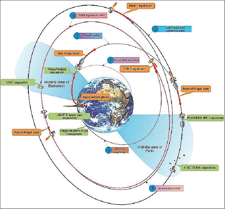
Flight deployment sequence (Figure 8): 9) 10)
- The Pleiades-HR1 (primary payload) was deployed first after 55 minutes at an altitude of ~694 km.
- The 4 ELISA satellites (secondary payloads) were released at ~ 700 km, 59 minutes after lift-off.
ELISA-1, ELISA-2, ELISA-3, ELISA-4 (Electronic Intelligence Satellite). A constellation of 4 ELINT (Electronic Intelligence) spacecraft of CNES/DGA, France. The ELISA demonstration constellation of microsatellites is based on the Myriade platform of CNES and was developed by by EADS/Astrium SAS and TAS-F (Thales Alenia Space-France) as co-prime contractors. Each ELISA spacecraft has a mass of 120 kg.
- This was followed by another orbit maneuver after which the SSOT satellite (secondary payload) separated from the Fregat stage, 3 hrs. 26 min. after lift-off at an altitude of ~620 km.
SSOT (Sistema Satelital para Observación de la Tierra) of ACE (Agencia Chilena del Espacio - Chilean Space Agency), Chile. SSOT is a high resolution optical Earth observation microsatellite which was designed, built, integrated and tested by EADS Astrium SAS of France. SSOT has a mass of 117 kg.
Orbit
Sun-synchronous near-circular orbit, nominal altitude = 620 km, inclination = 97.9º, period = 97.2 minutes, LTAN (Local equator crossing Time on a Descending Node) at 10:30 hours.
- Revisit period with ±3º spacecraft roll = 37 days.
- Revisit period with ±7º spacecraft roll = 21 days
- Revisit period with ±27º spacecraft roll = 5 days.
Mission Status
• On December 17, 2016, the SSOT Earth observation system of the Chilean government was 5 years on orbit. In Chile, the spacecraft is better known as "FASat-Charlie". The imagery is exploited in a wide range of applications such as mapping, agriculture, urban planning, military intelligence and natural resource, risk and disaster management. 11)
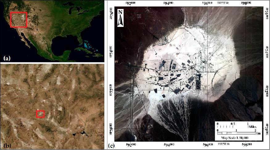
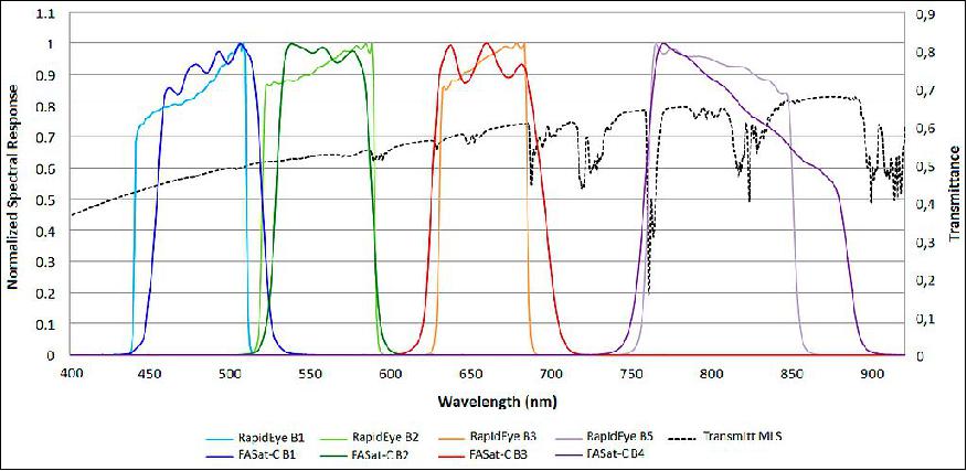
• July 21,2016: The NAOMI-1 (New AstroSat Optical Modular Instrument-1) sensor on SSOT/FASat-C has been cross-calibrated using SNOs (Simultaneous Nadir Overpasses) collected over the Frenchman Flat calibration site. RapidEye-MSI's (Multispectral Imager) radiometric response was used to update the absolute gains of FASat-C NAOMI-1 multispectral bands. A multitemporal EO-1 Hyperion dataset was utilized to derive an SBAF (Spectral Band Adjustment Factor), which has allowed the correction of one of the major sources of uncertainties in a cross-calibration study; leading to a substantial improvement in the degree of agreement between both sensors. The applied cross-calibration method will permit an adequate integration and a straightforward comparison of FASat-C and RapidEye data, as well as from other sensors, taking advantage of the higher joint revisit capability. 12)
- The cross-calibration study selected the REIS (RapidEye Earth Imaging System) instrument of the RapidEye constellation as reference sensor along with the SNO technique. The biases caused by differences in the spectral responses of both instruments were compensated through an adjustment factor derived from EO-1 Hyperion data. Through this method, the variations affecting the radiometric response of NAOMI-1, have been corrected based on collections over the Frenchman Flat calibration site.
- The Frenchman Flat calibration site is located in Nevada, USA, in the transition zone of the Mohave and Great Basin deserts (Figure 9). The area is a dry lake bed at 940 m above sea level; formed of fine-textured sedimentary deposits, mainly sand, gravel, silt and clay. The reflectance of the site is higher than 30% in the VIS/NIR domain, ensuring a high SNR (Signal-to-Noise Ratio). It presents a high degree of spatial homogeneity over an area that allows the absolute calibration of sensors having a GSD (Ground Sampling Distance) smaller than 300 m. Another characteristic of the area is its spectral uniformity, which contributes to minimizing the influence of SRF (Spectral Response Function) differences on the cross-calibration of satellite sensors.

• March 2014: The operational status of the SSOT satellite and its payload are in excellent condition after more than 2 years on orbit. 13)
• The SSOT spacecraft and its payload are operating nominally in 2013. 14)
• The SSOT system was declared operational on March 27, 2012. Astrium's teams have successfully completed the in-orbit delivery of the SSOT satellite system. In accepting delivery, the Chilean Air Force (FACh) confirmed that the conditions for the handover of the satellite, FASat Charlie, have been met in full within three months of its launch, thanks to its exceptional performance. 15)
Twenty Chilean engineers, operating SSOT, were trained at the Astrium site in Toulouse, France. The operational ground segment is based in Santiago, Chile.
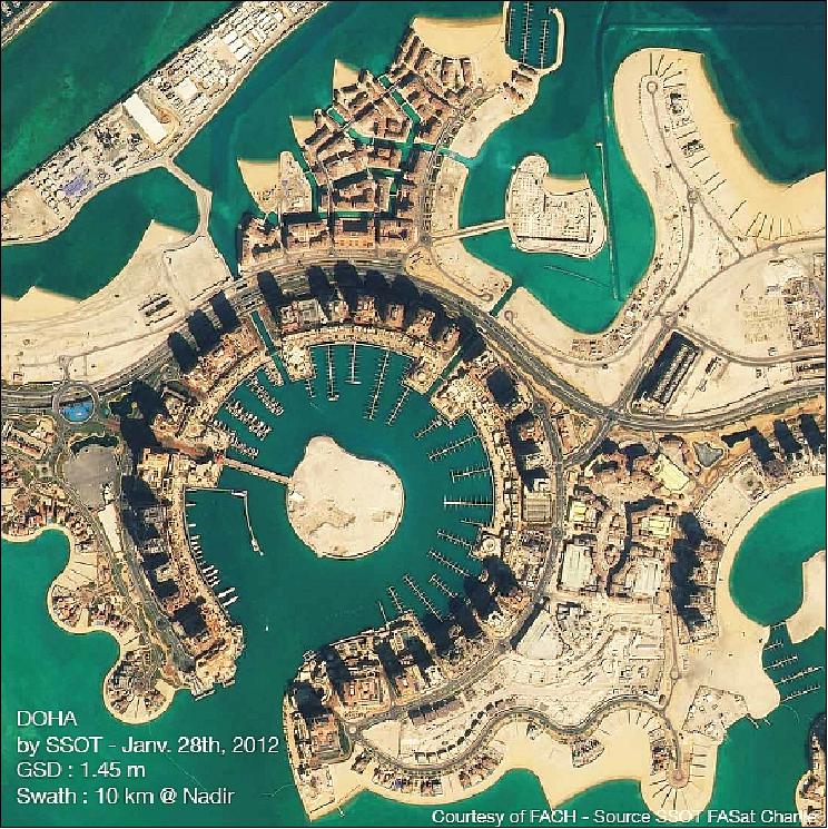
• On December 26, 2011, FACh announced the reception of the first imagery from FASAT Charlie. 17)

• SSC (Swedish Space Corporation) supported all 6 spacecraft of Astrium and CNES during the mission critical (7-10 days) LEOP (Launch and Early Operation Phase) from its Esrange station which is one of the network management centers of the PrioraNet, SSC's global high-capacity ground station network. 19)
Sensor Complement
The NAOMI optical imagery will be used for both, military and civil users of Chile.
NAOMI (New AstroSat Optical Modular Instrument)
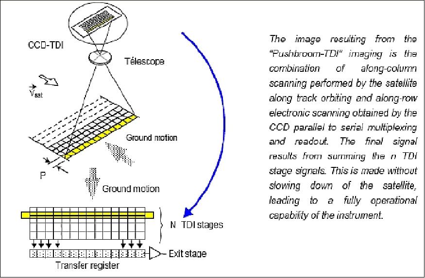
NAOMI is a high-resolution pushbroom imager designed and developed at EADS Astrium SAS: The instrument design is mainly driven by mission parameters and detector characteristics. The NAOMI instrument consists of a telescope, FEE (Front End Electronic), including the focal plane, and an IEU (Instrument Electronic Unit). A high MTF (Modulation Transfer Function) and SNR (Signal to Noise Ratio) are reached through the 200 mm pupil size and the use of a very advanced TDI (Time Delay Integration) detector.
The TDI mode in the Pan band enables to reduce the pupil size for a given GSD (Ground Sample Distance). The pupil diameter is no more sized to comply with SNR requirements which can be achieved by increasing the number of TDI stages and is only driven by MTF (Modulation Transfer Function) requirement.
Note: NAOMI is a copy of the imager flown on the AlSat-2 spacecraft of CNTS (Algerian National Space Technology Centre). However, some additional enhancements have been developed for the SSOT program in order to provide a 1.45 m ground sampling distance from the 620 km SSO orbit.
The imager provides imagery of ~1.5 m in Pan and 4 multispectral (MS) bands of ~6 m GSD. The optics system of the instrument employs state-of-the-art techniques such as SiC-100 (silicon carbide) material for the mirrors and the telescope structure, specific detectors, and a modular video chain design. 20) 21)
SiC is an outstanding material with the following characteristics:
- Very high stiffness and a low mass density
- Very high thermal conductivity and a low coefficient of thermal expansion
- The mirror surface can to be polished down to a roughness of a few angstrom (1Å= 10-10 m).
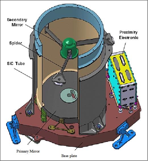
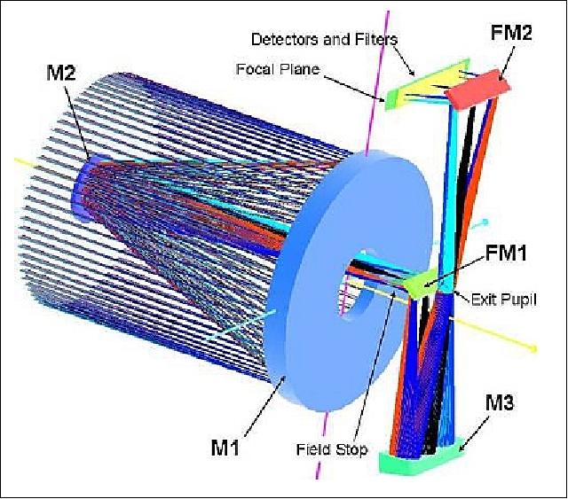
The primary structure is composed of three main parts: a baseplate, a cylindrical tube with a spider supporting the secondary mirror, and the focal plane. The structure also supports thermal MLI (Multi Layer Insulation).
The SiC primary mirror is mounted onto the baseplate via three isostatic Invar blades (FormoSat-2 heritage) providing good thermal decoupling between the telescope and the primary mirror. The secondary, tertiary and folding mirrors are also made of SiC. They have an incorporated isostatic foot. This type of attachment device, minimizes the number of interfaces, ensures a good thermal coupling with the structure, simplifies the integration, and improves the overall stability.
The focal plane accommodates detectors, filters and front-end electronics. All the elements are designed to cope with a multi-modules implementation capability.
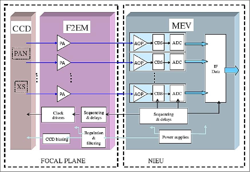
The detection chain is made of three main parts: the detectors, the F2EM (Front End Electronics Module) and the MEV (Module Electronique Video - Video Electronics Module) which are part of the NIEU (NAOMI Imaging and Electronics Unit).

Instrument type | Pushbroom imager |
Optics | - Korsch telescope with a TMA design in SiC (folded by 2 flat mirrors) |
Spectral band (Pan) | 0.45-0.9 µm |
MS (Multispectral bands), 4 | B1): 0.45-0.52 µm (blue |
GSD (Ground Sample Distance) | 1.45 m Pan at nadir |
Detectors | Silicon area array with 7000 pixels Pan, 1750 pixels in each MS band |
TDI (Time Delay Integration) | The Pan band offers TDI services for SNR improvement of the signal |
Swath width | 10.15 km at nadir, FOV = 0.94º |
FOR (Field of Regard) | ±30º (spacecraft tilting capability about nadir for event monitoring) |
Data quantization | 12 bit (10 bit coding for downlink) |
Instrument mass | 18.5 kg (including video electronics mass memory and payload internal harness). The camera has a mass of 13 kg. |
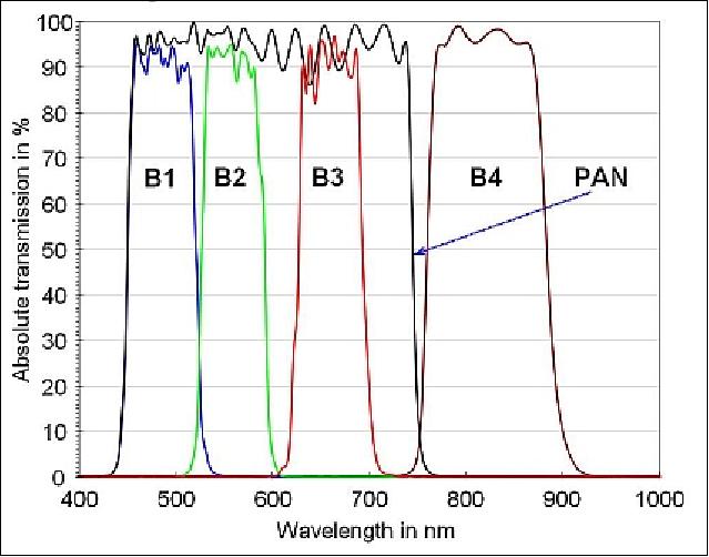
The optical filtering is ensured by highly integrated filters, including masks to minimize spectral cross-talk. The filters feature high band transmission, and sharp spectral band edges as illustrated in Figure 18.

The FPA (Focal Plane Assembly) of the Pan and MS bands represent the heart of the detection chain (Figures 16 and 21). The FPA was developed by e2v (UK) offering an unrivalled level of integration and performances. All the stringent constraints of dynamic range optimization and power consumption reduction have been mastered with < 1 watt detector dissipation.
The space qualified focal plane includes one TDI array of 7000 pixels for the panchromatic band and four lines of 1750 pixels for the MS (multispectral) bands. Antiblooming functions are adjustable via specific commands. The very good detector characteristics (high MTF and high quantum efficiency) significantly contribute to the instrument optical performance.

The MEV is the backend part of the NAOMI detection electronics. The MEV provides the F2EM with the primary power supplies and clocks necessary to front-end operation. The video signal from the F2EM is received, adapted and digitally converted to 12 bit in the MEV. The resulting data, rounded down to 10 useful bit, are then transmitted to the digital functions of the NIEU to be real-time processed and stored into the mass memory for downlinking during a station pass.
The NIEU represents the core of the electrical architecture. It consists of two main parts:
• the MEV is in charge of frontend operation, video processing, A/D conversion and transmission to the ICM via very high-speed digital link
• the ICM (Interface Control Module) encompasses the 64 Gbit mass memory and related FPGA (Floating Point Gate Array) based digital electronics and all the NAOMI housekeeping functions.

References
1) "Astrium wins Chilean optical Earth observation system," August 7, 2008, URL: https://web.archive.org/web/20100715043618/http://www.astrium.eads.net/node.php?articleid=374
2) Dominique. Pawlak, Thomas Schirmann, "The New Generation of Astrium Earth Observation Optical Systems," Proceedings of the Symposium on Small Satellite Systems and Services (4S), Funchal, Madeira, Portugal, May 31-June 4, 2010
3) Juan Fernando Acuña Arenas, "Space in Chile: Past, Present and Future," 53rd Session of UNCOPUOS, Vienna, Austria, June 9-18, 2010, URL: http://www.unoosa.org/pdf/p
res/copuos2010/tech-21E.pdf
4) Charles Koeck, Didier Radola, "AstroSAT 100 : Microsatellite solution for high resolution remote sensing systems," Proceedings of IAC 2011 (62nd International Astronautical Congress), Cape Town, South Africa, Oct. 3-7, 2011, paper: IAC-11-B4.4.4
5) Eric Maliet, Eric Beaufumé, Didier Radola, "AstroSat-100: Microsatellite Solution for High Resolution Remote Sensing Application," Proceedings of the 4S (Small Satellites Systems and Services) Symposium, Portoroz, Slovenia, June 4-8, 2012
6) "Sistema Satelital de Observación de la Tierra: Al Servicio del Desarrollo del País," URL: http://www.cartografia.cl/beta/index.php/home/percepcion/
663-sistema-satelital-de-observacion-de-la-tierra-qal-servicio-del-desarrollo-del-paisq
7) "VS02 - Mission Information," Spaceflight 101, URL: http://www.spaceflight101.com
/vs02-mission-information.html
8) http://www.arianespace.com/images/launch
-kits/launch-kit-pdf-eng/VS02-launchkit-GB.pdf
9) "Pleiades and ELISA satellites successfully launched," CNES, Dec. 17, 2011, URL: http://www.cnes.fr/web/CNES-en/9872-gp-plei
ades-and-elisa-satellites-successfully-launched.php
10) "Arianespace Completes 2011 Launch Manifest With Successful Soyuz Campaign," Space Travel, Dec. 17. 2011, URL: http://www.space-travel.com/report
s/Arianespace_Completes_2011_Launch_Manifest
_With_Successful_Soyuz_Campaign_999.html
11) "The Fifth Birthday of a Success Story," Airbus DS, December 2016, URL: https://airbusdefenceandspace.com/our-
portfolio/space-systems/earth-observation-satellites/national
-missions-worldwide/ssot-fasat-charlie/
12) Carolina Barrientos, Cristian Mattar, Theodoros Nakos, Waldo Perez, "Radiometric Cross-Calibration of the Chilean Satellite FASat-C Using RapidEye and EO-1 Hyperion Data and a Simultaneous Nadir Overpass Approach," Remote Sensing, Vol. 8, 612; doi:10.3390/rs8070612, July 21, 2016, URL: http://www.mdpi.com/2
072-4292/8/7/612/pdf
13) Information provided by Stéphane Castejon of Airbus DS (former EADS Astrium SAS), Toulouse, France.
14) Information provided by Philippe Luquet, NAOMI Product Line Manager, EADS Astrium SAS, Toulouse, France.
15) "Astrium successfully completes in-orbit delivery of the SSOT satellite system," Astrium, March 27, 2012, URL: https://web.archive.org/web/20120119112403/http://ilovechile.cl/2012/01/13/air-force-releases-stunning-images-transmitted-fasat-charlie-satellite/44857
16) Philippe Luquet, Laurant Brouard, Eric Chinal, Philippe Bernard, "NAOMI Instrument: A Product Line Of Compact And Versatile Cameras Designed For Hr & Vhr Missions In Earth Observation," ICSO (International Conference on Space Optics), Ajaccio, Corse, France, Oct. 9-12, 2012
17) Zoe Ackerman, "Air Force releases stunning images transmitted by "Fasat Charlie" satellite," Jan. 13, 2012, URL: http://ilovechile.cl/2012/01/13/air-
force-releases-stunning-images-transmitt
ed-fasat-charlie-satellite/44857
18) Alex Becerra, Marcos Diaz, Juan Cristobal Zagal, "Feasibility study of using a Small Satellite constellation to forecast, monitor and mitigate natural and man-made disasters in Chile and similar developing countries," Proceedings of the 26th Annual AIAA/USU Conference on Small Satellites, Logan, Utah, USA, August 13-16, 2012, paper: SSC12-IV-8
19) "SSC supports simultaneous launch of ELISA, Pleiades-1A and SSOT," Dec. 28, 2011, URL: http://www.sscspace.com/ssc-supports-simult
aneous-launch-of-pleiades-1a-elisa-and-ssot
20) Eric Maliet, Laure Brooker, Dominique Pawlak, "Global High Resolution Imaging for new Markets," Proceedings of the 59th IAC (International Astronautical Congress), Glasgow, Scotland, UK, Sept. 29 to Oct. 3, 2008, IAC-08-B1.2.7
21) P. Luquet, A. Chikouche, A. B Benbouzid, J. J Arnoux, E. Chinal, C Massol, P. Rouchit, S. de Zotti, "NAOMI instrument: a product line of compact & versatile cameras designed for high resolution missions in Earth observation," Proceedings of the 7th ICSO (International Conference on Space Optics) 2008, Toulouse, France, Oct. 14-17, 2008
22) Information provided by Hervé Lambert of EADS Astrium SAS, Toulouse, France
The information compiled and edited in this article was provided by Herbert J. Kramer from his documentation of: "Observation of the Earth and Its Environment: Survey of Missions and Sensors" (Springer Verlag) as well as many other sources after the publication of the 4th edition in 2002. - Comments and corrections to this article are always welcome for further updates (eoportal@symbios.space).
Overview Spacecraft Launch Mission Status Sensor Complement References Back to top