ST5 (Space Technology 5)
EO
Atmosphere
Atmospheric Temperature Fields
NASA
Quick facts
Overview
| Mission type | EO |
| Agency | NASA |
| Mission status | Mission complete |
| Launch date | 22 Mar 2006 |
| End of life date | 30 Jun 2006 |
| Measurement domain | Atmosphere, Gravity and Magnetic Fields |
| Measurement category | Atmospheric Temperature Fields, Gravity, Magnetic and Geodynamic measurements, Atmospheric Humidity Fields, Atmospheric Winds |
| Measurement detailed | Atmospheric stability index, Auroral Emissions |
| Instruments | Fluxgate magnetometer |
| Instrument type | Magnetic field, Atmospheric chemistry, Data collection |
| CEOS EO Handbook | See ST5 (Space Technology 5) summary |
ST5 (Space Technology 5)
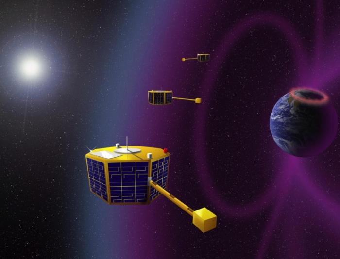
ST5 is a NASA mission within NMP (New Millennium Program) to test innovative concepts and new technologies for future missions in a microsatellite constellation of three spacecraft. The ST5 mission is considered to be a precursor mission to the Magnetospheric Constellation mission, a constellation of many nanosatellites also referred to as DRACO (Dynamic Response and Coupling Observatory). ST5 represents NASA's first experiment in the design of a full-service microsatellite constellation.
A major objective of ST5 is to dramatically reduce mass, size, power, and costs of the missions by providing acceptable functional capabilities. The S/C are used to test and validate methods for operating a constellation of three microsatellites as a single system in the SEC (Sun-Earth Connection) science theme. The science objectives are to measure the effect of solar activity on the Earth's magnetosphere. The ST5 mission is managed by NASA/GSFC and developed by JPL. The overall ST5 mission goals are: 1) 2) 3) 4) 5) 6)
• The design, development, integration, and operation of full service microsatellites (25 kg class) through the use of new technologies
• The ability to achieve accurate research quality measurements using this class of spacecraft
• The operation of multiple spacecraft to act as a single constellation rather than as individual elements.
Spacecraft
Each S/C in the constellation is spin-stabilized and provides the functions of propulsion, navigation, attitude control, command and data handling, and high-rate (X-band) RF communications. In addition, constellation management capabilities such as relative navigation, cross-platform communication, and ground-system autonomy are needed for affordable constellation operations. A service scenario is planned in which one spacecraft is able to adjust the data acquisition strategy of its companion spacecraft. This strategy and concept may serve as the basis for multiple platforms to act as a single unit.
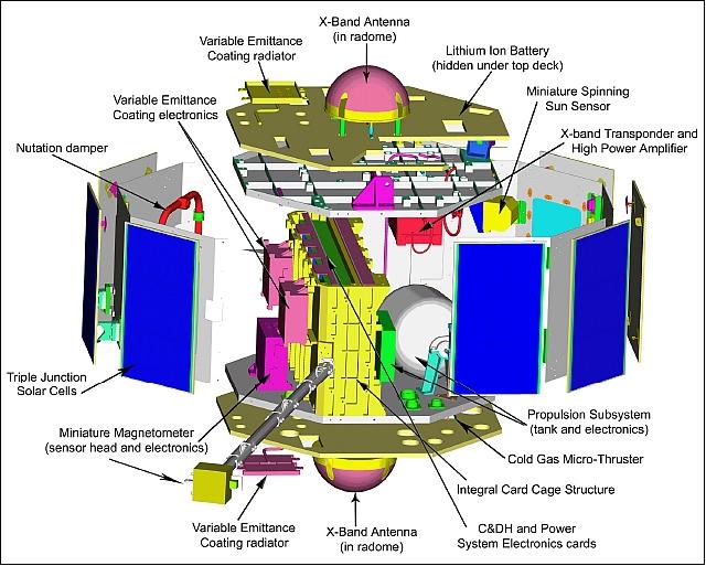
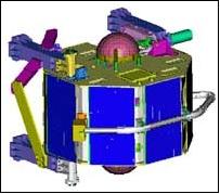
The S/C bus has been designed and built at NASA/GSFC. The S/C bus structure is an octagonal prism 53 cm in diameter and 48 cm high, each S/C features booms and antennas. The spacecraft ecliptic pole-pointing spin axis is the axis of symmetry or axis of rotation of the cylinder. The top and bottom “decks” are octagons, a total of eight small solar panels cover the outsides of the eight side walls of the cylinder.
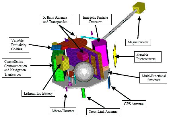
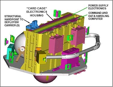
The spacecraft structure itself takes a significant step in integrating electronics into the primary structure. The multi-functional S/C design uses the “Card Cage” (a novel casting technique with very thin walls) technique as the primary structural load path, spanning the S/C width and tying the decks and all three hardpoint interfaces to the Deployer Structure (the Deployer structure supports the spacecraft at three distinct points through launch, and then imparts the required spin rate for mission operations). Three additional electronics boxes and the boom are mounted to the Card Cage exterior. 7) 8) 9) 10)
Core spacecraft subsystems include a high efficiency power subsystem, a magnetically clean structural and electrical system, a miniature digital sun sensor (DSS), a compact low-power flight computer with embedded flight software, a lightweight small volume mechanical structure and an all-passive thermal control system. Spacecraft power of 22-25 W at 7-9 VDC is provided by triple-junction solar cell arrays (8 panels/spacecraft, Emcore) and a lithium-ion battery with a capacity of 7.5 Ah (AEA Technology Space). The battery has a mass of 0.645 kg and a size of 12.7 cm x 6.5 cm x 8.6 cm.
The S/C mass is about 25 kg at launch, after deployment it is spun at 20 rpm. The ST5 mission duration is planned for three months.
RF Communication
The C&DH command uplink and telemetry downlink paths are CCSDS compliant. The RF uplink data rate is 1 kbit/s, the downlink data rate is selectable to be either 1, 100, or 200 kbit/s (X-band transponder communication system). Uplink codeblock error detection and de-randomization are performed on ground-to-spacecraft command frames. On the downlink path, cyclic redundancy check (CRC), Reed-Solomon encoding, pseudo-randomization and ½ rate convolutional encoding is performed on all telemetry frames as they are sent to the transponder for communication to the ground.
Launch
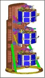
A launch of ST5 took place on March 22, 2006 on a Pegasus XL vehicle from VAFB, CA, USA. The ST5 Project designed, fabricated and tested also an innovative Pegasus launch rack that supports three microsatellites in a “stacked” configuration. By utilizing this type of multi-rack design, each microsatellite was individually deployed into a spinning motion. 11)
Orbit
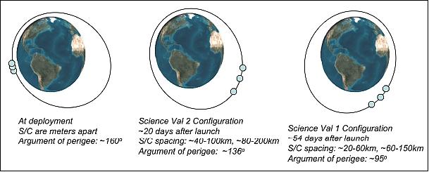
Elliptical sun-synchronous dawn-dusk orbit with a perigee of ~ 300 km, an apogee of ~ 4,500 km, inclination of 105.6º, period of 136 minutes (about 10.5 orbits/day). All three S/C share the same orbital plane, the separation distance between S/C near apogee is between 100-1000 km. The constellation configuration is being termed ”string of pearls.”
Enabling Technologies
Each microsatellite of the constellation carried to following technologies (demonstration and validation): 12)
• A miniature communications system to determine the positions of the spacecraft using the GPS constellation (NASA/JPL and Cincinnati Electronics Corp., Mason, OH).
• A set of software that automatically operates the spacecraft and determines orbits (Bester Tracking System, Emeryville, CA)
• Communications system component experiment for small S/C. Miniaturized X-band transponders, that use one-fourth the voltage and half the power, weigh 12 times less and are nine times smaller than proven technology (AeroAstro Inc.). A transponder, with a size of 5 cm x 5 cm x 7.6 cm and a mass of < 0.300 kg, is able to provide coherent uplink and downlink communications. Key performance parameters:
- Uplink 1 kbit/s; downlink 100 kbit/s
- BER < 1 x 10⁻⁵ for downlink
- The transponder was used routinely throughout the mission.
• A new method of connecting electrical lines that saves weight (Lockheed Martin, Denver, CO)
• Ultra Low-Power Demonstration. A new type of microelectronic device that is more reliable and uses 20 times less power than proven technology (Goddard Space Flight Center and the University of New Mexico, Albuquerque, NM).
• An electrically tunable coating that can change its properties from absorbing the sun's heat when the spacecraft is cool to reflecting or emitting heat when needed (Goddard Space Flight Center and the Johns Hopkins University Applied Physics Lab, Laurel, MD).
• Propulsion systems components. A very tiny micro-electromechanical system chip that provides fine attitude adjustments on the spacecraft using 8.5 times less power and weighing less than half as much as proven systems (Marotta Scientific Controls, Montville, NJ).
• Development of a lithium-ion power system for small satellites. A rechargeable lithium ion battery that stores two to four times more energy and has a longer life than proven technology (Yardney Technical Products, Pawcatuck, CT).
ST5 Spacecraft Technologies or Subsystems
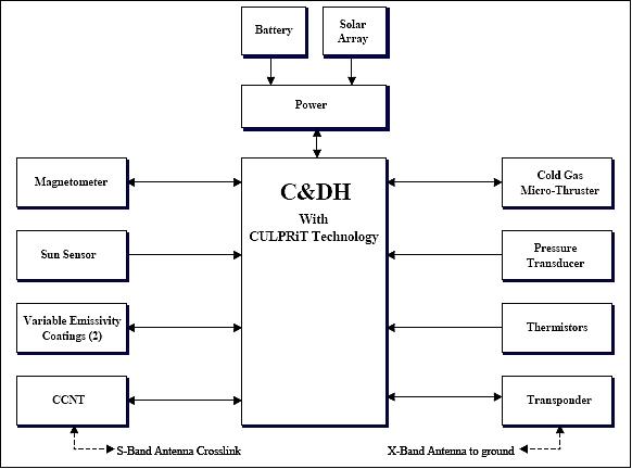
C&DH (Command and Data Handling) System
This is a single processor, multi-function flight computer which implements direct digital and analog interfaces to all onboard subsystems and components (no distributed systems such as the MIL-STD-1553 bus onboard ST5). C&DH is responsible for all real-time processing associated with: guidance, navigation and control, command and data handling including uplink/downlink, power switching and battery charge management, science data analysis and storage, intra-constellation communications, housekeeping data collection and logging. The C&DH's onboard solid state recorder (SSR) memory has error detection and correction (EDAC) and has a usable capacity of 15 MByte (data storage for 2 orbits). A single ADC (Analog-to-Digital Converter) on the C&DH board performs all digitization of analog telemetry. 13) 14) 15) 16)
The C&DH controls power distribution and autonomous power safing by performing command arming, verification and firing of power switch services. Control of deployment actuation is performed for the magnetometer boom and S-band crosslink antenna. The C&DH also controls magnetometer sensitivity, emittance setting for the variable emittance controllers, X-band transponder operational mode, and thruster firing. In addition, there is low-pass filtering and science event detection on the MAG data.
The C&DH is designed to be single event latch-up immune, with radiation hardening for up to 40 krad of total ionization dose, and a single event upset LET threshold of 35 MeV cm2/mg. The C&DH board size is: 45 cm x 22 cm x 3 cm, mass = 1.5 kg, the average power consumption is < 5.5 W.
The C&DH (flight computer) hardware employs three FPGAs (Field Programmable Gate Array), one for uplink/downlink communication to the X-band transponder, and a second one for spacecraft timer and thruster control functions. A combined analog telemetry signal collection and direct memory access (DMA) controller is implemented in the third FPGA to off-load much of the processing required to handle multiple, asynchronous data streams and greatly reduce the average processor interrupt frequency. The FPGAs also have built-in triple mode redundancy to reduce the probability of single event upsets.
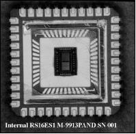
CULPRiT (CMOS Ultra Low-Power Radiation-Tolerant)
The CULPRiT logic technology was provided by the Advanced Microelectronics and Bimolecular Research at the University of Idaho. The objective is to demonstrate a CULPRiT Reed-Solomon encoder in the telemetry downlink path. Also, validation of the CULPRiT concept as an integral part of the C&DH subsystem. CULPRiT features 0.25 V transistor threshold technology (1/20 of the conventional transistor logic voltage), it is latchup immune and hardened for up to 100 krad of total ionization dose. The bias control is implemented with a 10 kHz pulse-width modulated digital signal in conjunction with an analog low-pass filter. CULPRiT also provides data compression on a single chip developed by the Institute of Advanced Microelectronics at the University of New Mexico. 17) 18) 19)
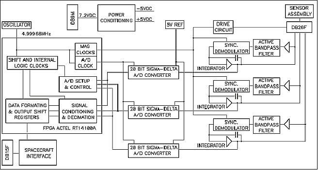
MAG (Miniature Fluxgate Magnetometer)
MAG is a research-grade instrument developed at UCLA. MAG has a measurement range of ±1 to ±64,000 nT. In high resolution mode (programmable), MAG can sense fields from approximately 0.1 nT up to about ± 1000 nT. The MAG “vectors” are generated at a regular 16 Hz rate (every 62.5 ms) inside the MAG electronics. 20) 21)
Total mass of instrument | 0.611 kg |
- Electronic unit volume | 10 cm x 20 cm x 5 cm |
- Power consumption electronics | 500 mW |
Range selection | 1000 nT, 64,000 nT |
Data rate | 16 vectors/s |
Data resolution | 18 bit (1:range, 1:sign, 16:value) |
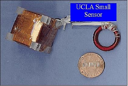
A deployable MAG boom positions the magnetometer's sensor head about 1 m away from S/C center. Each S/C of ST5 processes its magnetometer data in real-time, and is capable of both alerting other spacecraft to the presence of science events, and receiving alerts to collect magnetometer science data at a high rate. The MAG data will also be used as part of a ground-based attitude determination algorithm.
MAG is a low-power high-resolution science instrument on ST5 with the objective to perform in-situ measurements of the Earth's magnetic field throughout the orbit. ST5's satellites will map the intensity and direction of magnetic fields within the inner magnetosphere. These measurements will allow to directly infer the presence of electrical currents carried by energetic charged particles.
DSS (Digital Sun Sensor)
An angle measurement of the spinning S/C is generated every 3 s when the sun passes through the FOV of the DSS. This information is being collected by the FSW (Flight Software) of C&DH.
CCNT (Constellation Communication & Navigation Transceiver)
CCNT was developed at JPL. The objective of CCNT is to provide intra-constellation, S-band crosslink communication of data and “science events” between the three spacecraft. The CCNT includes a GPS receiver to allow orbit determination and inter-spacecraft ranging measurements. Each spacecraft in ST5 carries a CCNT. The instrument is in fact a multi-function payload that provides for inter-constellation ranging, communications, and GPS-based absolute positioning. The CCNT is capable of both generating and interpreting a GPS-like pseudo random noise (PRN) code. This implies a fundamental communications capability, which is further enhanced to allow for coding and decoding of non-range data modulated on the carrier. NASA selected the RTOS (Real-Time Operating System) of GHS (Green Hills Software) and a reconfigurable network processor for CCNT to perform autonomous radiometric tracking. A CCNT device has the following instrument constraints: mass of 1.5 kg; power: 1 W transmit, 12 W peak; size: 18 cm x 8 cm x 16 cm. 22)
The CCNT is using a single S-band to transmit and receive. ST5's radiometric measurements include 1-way and 2-way Doppler, as well as 1-way and 2-way phase and range. The accuracy requirements for the CCNT are fairly loose: only 1 m ranging. But the transmit power limitation coupled with the long inter-constellation ranges make it a challenging requirement nonetheless. Additional requirements call for a communications function - to transfer certain messages between spacecraft (science event alerts) with < 1 s latency at a data rate of 1kbit/s at 1000 km range.
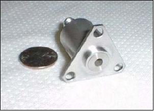
CGMT (Cold Gas Micro-Thruster)
CGMT consists of a high-pressure tank, a pressure sensor, and truster. The objective is to provide attitude control (maintenance of spin) and stationkeeping capabilities to a spacecraft. Each spacecraft uses a single thruster in a blow-down cold gas system. Thrust begins at ~2.36 N thrust @ 154 bar GN2 then becomes ~105 mN thrust @ 7 bar GN2 at near exhaustion after blowdown. The minimum impulse bit is 44 mNs. 23) 24)
Power consumption (5 VDC bus voltage) | 2 W @ 5.23 VDC |
Thruster mass | 78 grams, including lead wires |
Minimum impulse | 430 m/s (or 44 mNseconds) |
Operational modes | Pulsed and continuous |
Cycle life, duty cycle | >1000 cycles, 10-90% at 1 Hz |
VEC (Variable Emittance Controller)
These are (2) variable emittance controllers for the thermal subsystem.
Spacecraft Operations
Each microsatellite may be commanded individually from ground stations on Earth, except for a one-week period of ”lights out” operations. During this time, the microsats will fly ”autonomously” with pre-programmed commands in a test to find out whether ground commanding (for 24 hours) is really necessary. 25) 26) 27)
Operation of multiple spacecraft as a single constellation:
• Demonstrated concepts for autonomous constellation management and autonomous operations
• Accommodated downlink and ground data processing of multiple data streams from multiple spacecraft
• Performed model-based constellation health and safety management
• Performed simulated “lights out” operations for one week (June 11-18, 2006)
About 81% data return was achieved (80% requirement) despite sub-optimal ground station visibility.
Status of Mission
The ST5 mission team concluded all mission operations up to June 30, 2006, completing all major demonstration objectives within the planned mission life of three months. Between June 26 and June 29, 2006, a series of 11 EOM thruster firings were successfully conducted on the three ST5 spacecraft and final contact with them was on June 30, 2006. After conducting these operations, the spacecraft would re-enter the atmosphere well within 25 years and with no debris field, meeting NASA orbital debris requirements. 28) 29) 30)
• Next to the demonstration objectives the constellation mission returned high quality multi-point magnetic field data through the Earth's dynamic ionospheric current systems. These data allow the separation of spatial versus temporal structures of auroral field-aligned currents over a wide range of spatial (~ 50-4000 km) and temporal (~ 5 s-10 min) scales. Based on the success of ST5, NASA/GSFC is developing the concept of a new constellation mission, called Magnetospheric Convection Explorer (CONVEX), using ~10 small ST5-class spacecraft, distributed in local time around the Earth to complement the THEMIS mission's radial deployment. The science approach is to generate the first global “images” of magnetospheric convection. This will allow definitive determinations of how major types of solar events drive specific space weather response modes in the near Earth environment. 31)
• In less than a month after launch, the ST5 team had checked out the ST5 spacecraft and successfully activated all technologies.
• A major milestone of the mission was reached when the spacecraft assumed a constellation formation on May 24, 2006. The satellites lined up in nearly identical orbits, like three pearls on a necklace, approximately 100-400 km apart. Reaching formation required seven maneuvers using miniaturized micro-thrusters. Each spacecraft has a single micro-thruster the size of a quarter to perform both attitude- and orbit-adjustment maneuvers.
• The mission demonstrated the benefits of using a constellation of spacecraft to perform scientific studies of the beautiful auroral displays that occur near Earth's polar regions. The spacecraft simultaneously traversed electric current sheets and measured the magnetic field using miniature magnetometers.
- ST5 provided for the first time simultaneous multi-point measurements of auroral electric currents at low altitudes, which allow us to separate temporal and spatial variations of these currents
- ST5 provided a unique data set on the Earth's crustal magnetic field, which is a consequence of both the constellation flying, and the enhanced resolution from the low perigee, lower than any previous geomagnetism mission.
• The mission validation team demonstrated the sensitivity of miniature magnetometers, and suitability of the satellites for supporting scientific measurements.
• The mission also demonstrated an innovative communications technology.
• During the final days of the mission, the emphasis was on demonstrating ground system technologies. The ground system is highly automated to reduce the cost of operating multiple spacecraft as a single constellation rather than operating them individually. This type of ground system will help pave the way for an affordable means of simultaneously flying constellations from 10 to hundreds of microsatellites.
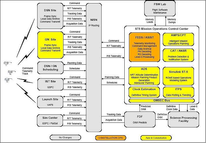
Introduction of the GMSEC (GSFC Mission Services Evolution Center) Bus in ST5
GMSEC is an integrated effort across multiple GSFC organizations to provide GSFC mission services through the year 2010. GMSEC provides mission enabling and cost and risk reducing data system solutions applicable to current and future Space and Earth Sciences’ missions. GMSEC will enable the continued recognition of GSFC as a leader in space mission expertise and services. 32) 33) 34) 35) 36)
The GMSEC bus architecture provides a scalable and extensible ground and flight system approach to enable cost-effective model-based operations to run the ST-5 constellations lights-out: (Ref. 27)
• Standardized messages formats
• Plug-and-Play (PnP) components
• Publish/Subscribe protocol
• Platform transparency.
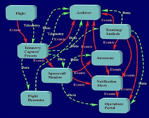
The GMSEC approach gives users choices for the components in their system. By creating a “framework”, individual applications can be easily integrated into an existing system without regard to many underlying implementation details.
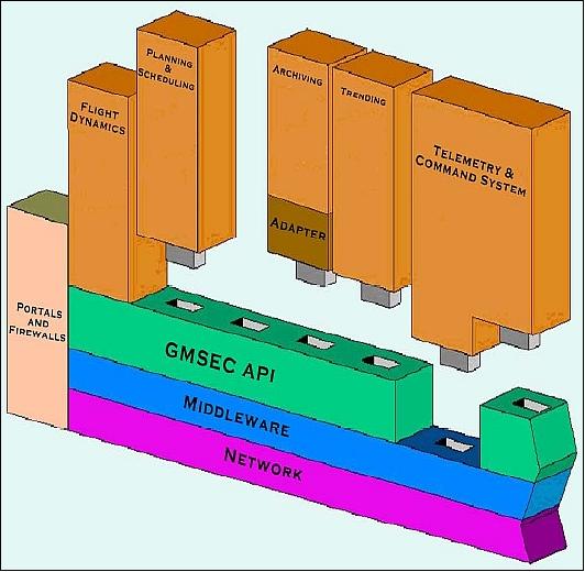
The keys to the GMSEC architecture are standard messages and message formats defined by the GMSEC team with industry involvement to ensure wide support and flexibility. By using standard messages, the event driven architecture enables quick and easy integration of functional components, in a "plug and play" concept for current and future missions. The system components are selected to meet the unique needs of a mission or user. Messages are passed between applications by an information software bus using the publish/subscribe paradigm. Application components maintain an interconnection to the information software bus that isolates most of the components’ complexity from other components. Since applications communicate using known, defined messages, the architecture also enables the addition, deletion, and exchange of components to meet the changing requirements of missions as they progress through their lifecycles. The GMSEC API (Application Program Interface) provides a multi-language, cross-platform, standard communications interface, which is easily integrated to any application. 37)
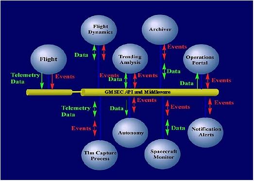
Legend to Figure 17: The middleware simplifies integration by having components interface to a bus and not to each other.
GMSEC Message Bus
All messages are exchanged through a multi-platform API (Application Program Interface), which sends them via powerful middleware. Different products are available for the middleware, each with varying capabilities, but all providing a minimum requirement of connectivity. This middleware is abstracted as the GMSEC bus layer, which integrates the GMSEC API so applications can directly use whichever middleware implementation that exists underneath.
The integration of legacy software into GMSEC is normally performed by developing an adapter. It plugs into the GMSEC API and converts the applicable incoming GMSEC messages into calls to the API of the legacy software. In the same way, information generated by the legacy software (e.g. events, products, etc.) is converted into GMSEC messages by the adapter. New GOTS (Government of-the-Shelf) and COTS (Commercial off-the-Shelf) components/subsystems developed for NASA missions are expected to provide native support for the GMSEC API.
Vision: Provision of a “Sensor Web Enablement” via SOA (Service Oriented Architecture). 38)
Background
The GMSEC architecture is a conglomeration of tasks built around a message bus architecture established in 2001 to coordinate ground and flight data systems development and services at GSFC. The auto configuration system provides ubiquitous configuration management for all components running on a mission operation center. This is accomplished by creating a set of GMSEC compliant configuration management agent (CMA) tools, extensions to the GMSEC API as well a self-configuring middleware (GMSEC message bus). Automatic configuration is part of the autonomic computing model being developed for net generation missions at GSFC. The core of the system is handled by a special purpose middleware design and implementation. The GMSEC message bus is the central part of the entire system. It handles all communication between the CMA and the GMSEC API core extension. The CMA is a GMSEC component that uses the message bus for communications. Similarly, the GMSEC API core extension uses the GMSEC message bus to communicate with any present CMAs in the network.
References
1) G. Chen, J. Oberright, “Integrating Robustness into ST5 Nanosatellite Development for Inexpensive Space Missions,” ISU International Symposium: Smaller Satellites - Bigger Business? Strasbourg, France, May 21-23, 2001
2) http://www.nasa.gov/mission_pages/st-5/main/index.html
3) http://nmp.jpl.nasa.gov/st5/
4) C. C. Carlisle, E. J. Finnegan, , “Space Technology 5: Pathfinder for Future Micro-Sat Constellations,” Proceedings of the IEEE Aerospace Conference, Big Sky, MT, March 6-13, 2004
5) C. C. Carlisle, G. Le, J. A. Slavin, J. T. VanSant, E. H. Webb, “Space Technology 5 - Technology Validation Update,” Proceedings of the 2006 IEEE/AIAA Aerospace Conference, Big Sky, MT, USA, March 4-11, 2006
6) C. Carlisle, E. H. Webb, “Space Technology 5 - A Successful Micro-Satellite Constellation Mission,” Proceedings of the 21st Annual AIAA/USU Conference on Small Satellites, Logan, UT, USA, Aug. 13-16, 2007, SSC07-VII-6
7) P. Rossoni, “Design and Verification of a Mechanical System for Magnetospheric Mapping Missions,” Proceedings of the IEEE Aerospace Conference, Big Sky, MT, March 6-13, 2004
8) P. Rossoni, W. McGill, “Novel Design Elements of the Space Technology 5 Mechanical Subsystem,” Proceedings of the AIAA/USU Conference on Small Satellites, Logan, UT, Aug. 11-14, 2003, SSC03-X-6
9) http://nmp.nasa.gov/st5/ABOUT/about-index.html
10) P. Rossoni, “Structural Bus and Release Mechanisms on the ST5 Satellites - Summary and Status,” Proceedings of the 2007 IEEE Aerospace Conference, Big Sky, MT, March 3-10, 2007
11) Space Technology 5 News Media Kit, Feb. 22, 2006, URL: http://www.nasa.gov/pdf/143648main_ST5PressKit.pdf
12) http://nmp.jpl.nasa.gov/st5/TECHNOLOGY/enabling.html
13) C. Carlisle, G. Le, “Space Technology 5 - Technology and Constellation Validation,” Proceedings of the 6th Annual ESTC (Earth Science Technology Conference), College Park, MD, USA, June 27-29, 2006
14) D. Speer, G. L. Jackson, D. Raphael, “Flight Computer Design for the Space Technology 5 (ST5) Mission,” Proceedings of the IEEE Aerospace Conference, Big Sky, MT, March 9-16, 2002
15) D. Raphael, P. Luers, V. Sank, G. Jackson, “Timekeeping for the Space Technology 5 (ST5) Mission,” Proceedings of IEEE Aerospace Conference,” Big Sky, MT, March 8-15, 2003
16) Candace C. Carlisle, Guan Le, “Space Technology 5: Technology Validation Results,” NSTC2007 (NASA Science and Technology Conference 2007), June 19-20, 2007, College Park, MD, USA, URL: http://esto.nasa.gov/conferences/nstc2007/papers/Carlisle_Candace_D1P1_NSTC-07-0034.pdf
17) M .A. Xapsos, “Technology Readiness Overview: CMOS Ultra-Low Power Radiation Tolerant (CULPRiT) Integrated Circuits,” URL: http://nepp.nasa.gov/DocUploads/BA75E948-978C-4225-BE60A3756C620FA6/CULPRiT_Overview.pdf
18) Jody W. Gambles, Kenneth J. Hass, Sterling R. Whitaker, “Radiation Hardness of Ultra Low Power CMOS VLSI,” URL: http://www2.cambr.uidaho.edu/symposiums/symp11/JodyGamblesPaper.pdf
19) K.E. Li, M. A. Xapsos, C. Poivey, K. A. LaBel, R. F. Stone, P.-S. Yeh, “Evaluation of an Ultra-Low Power Reed Solomon Encoder for NASA’s Space Technology 5 Mission,” HEART Conference, Albuquerque, NM, March 13, 2003, URL: http://nepp.nasa.gov/docuploads/101E287D-3F21-43DF-A1B8E638ABFE9A4C/HEART03_Xapsos.pdf
20) http://www-ssc.igpp.ucla.edu/st5/design.html
21) R. J. Strangeway, C. T. Russell, M. B. Moldwin, J. A. Slavin, G. Le, “Magnetometers for Space Technology 5,” Geophysical Research Abstracts, Vol. 5, 13375, 2003
22) Y. Bar-Sever, W. Bertiger, J. Srinivasan, “The Constellation Communications and Navigation Transceiver (CCNT) and the Proximity Navigation Experiment on NASA's ST5 Constellation Mission,” NAVITEC 2001, 1st Workshop on Satellite Navigation User Equipment Technologies, Dec. 10-12, 2001, ESA/ESTEC, Noordwijk, The Netherlands
23) M. S. Rhee, C. M. Zakrzwski, M. A. Thomas, “Highlights of Nanosatellite Propulsion Development Program at NASA-Goddard Space Flight Center,” Proceedings of the AIAA/USU Conference on Small Satellites, Logan, UT, Aug. 21-24, 2000, SSC00-X-5
24) D. T. Schappell, E. Scarduffa, P. Smith, N. Solway, ”Advances in Marotta Electric and Satellite Propulsion Fluid Control Activities,” 41st AIAA/ASME/SAE/ASEE Joint Propulsion Conference & Exhibit, July 10-13, 2005, Tucson, AZ, paper AIAA 2005-4055
25) Alexander C. Calder, “On-Orbit Maintenance of a Short Duration Mission: Space Technology 5,” Nov. 13, 2008, URL: http://www.flightsoftware.org/files/FSW08_Calder.ppt
26) Terri Wood, Robert Shendock, Jenny Williams, “Automated Mission Planning and Scheduling (AMPS) Support of Autonomous Operations for the ST5 Constellation,”5th International Workshop on Planning and Scheduling for Space, Oct. 22-25, 2006, Baltimore, MD, USA, URL: http://www.stsci.edu/institute/itsd/information/streaming/archive/IWPSS2006/R...
27) Bob Shendock, Ken Witt, Jason Stanley, Dan Mandl, Steve Coyle, “Flying the ST-5 Constellation with “Plug and Play” Autonomy Components and the GMSEC Bus,” 10th Anniversary GSAW (Ground System Architectures Workshop), March 27-30, 2006, Manhattan Beach, CA, USA, URL: http://sunset.usc.edu/GSAW/gsaw2006/s8/mandl_witt.pdf
28) http://www.nasa.gov/home/hqnews/2006/jun/HQ_06254_microsatellites.html
29) NASA Space Technology 5 (ST5) Status Report, URL: http://www.nasa.gov/mission_pages/st-5/news/HQ_06-29_ST5_status.html
30) J. R. O'Donnell, Jr., M. Concha, D. C. Tsai, S. J. Placanica, J. R. Morrissey, A. M. Russo, “Space Technology 5 Launch and Operations,” Proceedings of the 30th Annual AAS GNC 2007 (Guidance & Navigation Conference), Breckenridge, CO, USA, Feb. 3-7, 2007, AAS 07-091, URL: http://ntrs.nasa.gov/archive/nasa/casi.ntrs.nasa.gov/20070018186_2007017323.pdf
31) Guan Le, Thomas E. Moore, James A. Slavin, “Space Technology 5 - Enabling Future Constellation Missions Using Micro-Satellites for Space Weather,” Proceedings of the 21st Annual AIAA/USU Conference on Small Satellites, Logan, UT, USA, Aug. 13-16, 2007, SSC07-IV-6
32) http://gmsec.gsfc.nasa.gov/
33) Dan Smith, “NASA’s Goddard Mission Services Evolution Center (GMSEC) - A Proven Ground System Reference Architecture,” March 1, 2006, URL: https://www.ncoic.org/apps/group_public/download.php/2879/NASA%20GMSEC%...
34) Everett Cary, Dan Smith, “A Modular, Data Driven System Architecture for GSFC Ground Systems - GSFC’s Mission Services Evolution Center (GMSEC),” GSAW 2004 (Ground System Architectures Workshop), Manhattan Beach, CA., USA, March 29 – April 1, 2004, URL: http://sunset.usc.edu/GSAW/gsaw2004/s10f/cary.pdf
35) Dan Smith, John Bristow, Patrick Crouse, “Reducing Development and Operations Costs Using NASA's 'GMSEC' Systems Architecture,” '7th International Symposium Reducing the Costs of Spacecraft Ground Systems and Operations, June 11-15, 2007, Moscow, Russia, URL: http://ntrs.nasa.gov/archive/nasa/casi.ntrs.nasa.gov/20070035885_2007033941.pdf
36) Jean-Pierre Chamoun, Steve Risner, Theresa Beech, Gonzalo Garcia, “Bridging ESA and NASA Worlds: Lessons Learned from the Integration of hifly®/SCOS-2000 in NASA’s GMSEC, Proceedings of the 2006 IEEE/AIAA Aerospace Conference, Big Sky, MT, USA, March 4-11, 2006
37) Jim Busch, John Bristow, “Goddard Space Flight Center’s (GSFC) Mission Services Evolution Center (GMSEC) Architecture,” 11th Annual Enhancing Space Operations Workshop, May 4-5, 2005 , Houston, TX, USA
38) Dan Mandl, Stuart Frye, Pat Cappalaere Vightel, “Transforming Space Missions Into Service Oriented Architectures,” Sept. 12, 2006, URL: http://www.geobliki.com/files/SOA_for_Sensor_Webs_-_GGF18_Presentation_9-12-06_v2.ppt
The information compiled and edited in this article was provided by Herbert J. Kramer from his documentation of: ”Observation of the Earth and Its Environment: Survey of Missions and Sensors” (Springer Verlag) as well as many other sources after the publication of the 4th edition in 2002. - Comments and corrections to this article are always welcome for further updates (eoportal@symbios.space).