TurkSat-3USat (Turkish Satellite - 3U Satellite)
EO
Atmosphere
Ocean
Multi-purpose imagery (ocean)
Quick facts
Overview
| Mission type | EO |
| Agency | ITU |
| Mission status | Operational (extended) |
| Launch date | 26 Apr 2013 |
| Measurement domain | Atmosphere, Ocean, Land, Gravity and Magnetic Fields |
| Measurement category | Multi-purpose imagery (ocean), Multi-purpose imagery (land), Gravity, Magnetic and Geodynamic measurements |
| Instrument type | Space environment, Other, Communications, Data collection, Hyperspectral imagers |
| CEOS EO Handbook | See TurkSat-3USat (Turkish Satellite - 3U Satellite) summary |
TurkSat-3USat (Turkish Satellite - 3U Satellite)
TurkSat-3USat is a 3U CubeSat, the first communication nanosatellite mission of ITU (Istanbul Technical University), Istanbul, Turkey. TurkSat-3USat is a follow-up project based on the ITUpSat-1 (Istanbul Technical University PicoSatellite-1) mission which was launch on Sept. 23, 2009. ITUpSat-1 is operating nominally in 2012. The TurkSat-3USat project was started in 2010. 1) 2) 3)
The payload of the TurkSat is a VHF/UHF linear transponder to be used for voice communication. A deorbiting system is also designed to deorbit the satellite following its end-of-life to comply with the current CubeSat standard and United Nations regulations. The nanosatellite has sufficient volume for all the systems with full redundancy. Both in-house developed systems based on COTS components and readily available commercial CubeSat systems are used together to achieve redundancy. 4)

Spacecraft
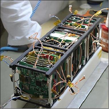
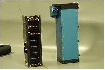
TurkSat-3USat features a 3U CubeSat structure of ISIS (Innovative Solutions In Space BV), Delft, The Netherlands, with a size of 10 cm x 10 cm x 30 cm. The total mass of the nanosatellite is ~ 4 kg. The nanosatellite was developed collaboratively by TURKSAT Inc. and ITU/SSDTL (Space Systems Design and Testing Laboratory) along with TAMSAT (Turkish Amateur Satellite Technology Organization). 5)
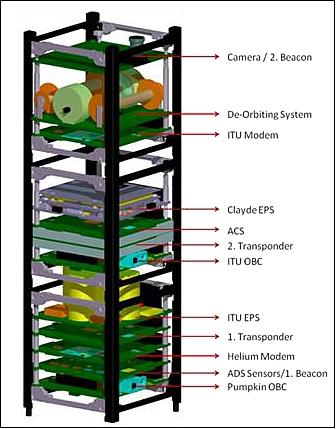
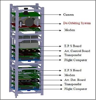
The interior configuration of the nanosatellite (Figure 2) is based on the following considerations:
• Geometric constraints of the ISIS nanosatellite structure
• A Pumpkin OBC is located at the bottom-most card, due to the standard PC/104 stack through the connector.
• The camera/second beacon card is accommodated at the top-most card for optimal FOV (Field of View) conditions.
• The ADCS (Attitude Determination and Control Subsystem) is a passive magnetic attitude stabilization system consisting of a permanent magnet and magnetic hysteresis rods. To provide the necessary attitude stabilization and motion damping of the nanosatellite, the ADCS must be positioned close to mass and geometry center of the satellite. It should be understood that ADCS is required to be in the middle of the satellite and the placement of the ADCS is made accordingly.
• The 3U structure of ISIS is composed of three separate 1U elements. The distance between the two electronic cards in the transition region between adjacent 1Unit elements is about 50 mm. The most suitable electronic card for this region is the ITU EPS (Electrical Power Subsystem) which includes the battery and capacitors. A thermal analyses showed that the middle unit of the nanosatellite displays only a mild gradient in environmental temperature. Hence, both EPS cards (Clyde Space) are identified as top-positioned cards of the first and second units.
• As a result of the thermal analysis, the transponders are accommodated under the EPS cards to heat the batteries. The transponders, with an efficiency of 40%, consume 2.7 W of power.
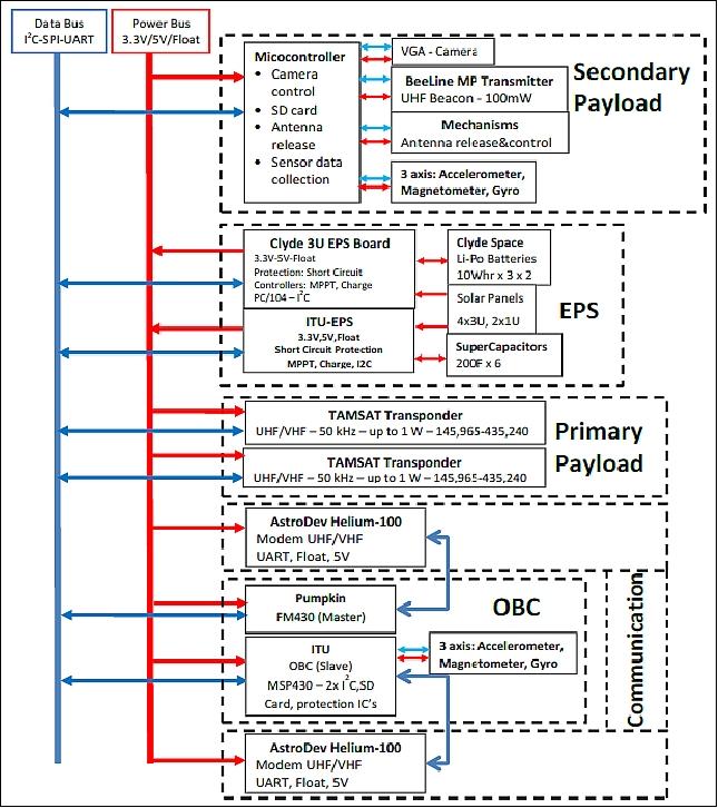
EPS (Electrical Power Subsystem): Two units are provided. The primary unit from Clyde Space features 3 MPPT (Maximum Power Point Tracker) charge controllers, one for each axis. Energy is stored using Li-Polymer batteries in 2 series configuration. The batteries have a heating system for cold eclipses. The main EPS provides to the power bus 3.3 V and 5 V regulated voltage and a floating battery voltage.
The secondary system is being developed at ITU. It also features 3 MPPT controllers with perturb and observe algorithm. Energy is stored in supercapacitors. The supercapacitors provide less Wh/ kg than the Li-Polymer battery, but they have a much longer lifetime and better temperature characteristics. The two lithium-polymer supercapacitors are implemented in a series configuration to store the energy for eclipse operations. The standard operating voltage is between 2.2 V and 3.8 V for the chosen supercapacitor.
The solar panels will be provided mostly by Clyde Space. One of the solar panels will be produced at ITU. A quick demonstration panel is built from a 2 sided PCB.
Energy requirement (worst case) | Power (W) | Time (minutes) | Energy (Whr) |
Transponder | 2.8 | 35 | 1.6333 |
OBC | 0.1 | 35 | 0.0583 |
Beacon | 0.5 | 15 | 0.125 |
ADCS | 0.3 | 5 | 0.025 |
Modem | 1 | 10 | 0.1666 |
Total | 2.008 | ||
ADCS (Attitude Determination and Control Subsystem): The mission has no precise pointing requirement; hence, the satellite will be controlled passively by onboard magnetic moment production. No onboard attitude estimation is required for the passively controlled nanosatellite. Therefore, the angular motion will be only sensed by the 9 DOF (Degree of Freedom) sensor unit of the satellite, and the transferred measurement data will be processed on ground to determine the attitude states corresponding to angular motion measurement sets.
Launch
The TurkSat-3USat nanosatellite was launched a secondary payload on April 26, 2013 on a Long March 2D (CZ-2D) vehicle of China. The launch site was the Jiuquan Satellite Launch Center, China. The primary payload on the flight was GF-1 (Gaofen-1), an Earth observation mission of CNSA. 6) 7)
Orbit
Sun-synchronous orbit, altitude of 680 km, inclination =98.06º.
The secondary payloads were:
• TurkSat-3USat, a nanosatellite (3U CubeSat, ~ 4 kg) of ITU (Istanbul Technical University), Istanbul, Turkey.
• NEE-01 Pegasus, a 1U CubeSat of EXA (Ecuadorian Civilian Space Agency), Ecuador.
• CubeBug-1 of INVAP, a 2U CubeSat of Argentina, sponsored by the Argentinian Ministry of Science, Technology and Productive Innovation, INVAP S.E., Satellogic SA, and Radio Club Bariloche.
Mission Status
• Following launch, the TurkSat-3USAT transmitted signals that showed the project successful operation for over a day. However, for some undetermined reasons the nanosatellite turned silent. ITU/SSDTL, TURKSAT Inc. and radio amateurs have been trying to establish communication since then. The research on the engineering model is continuing to find any possible cause for the silence (Ref. 5).
The project was developed for voice communication at LEO, to provide radio amateur world a long awaited opportunity. The project was sponsored by TURKSAT Inc. University labs of different disciplines (aerospace, mechanical, electric-electronics, control, manufacturing) along with industry and Turkish radio amateurs worked together to develop the 3USAT.
Many faculty members, engineers, undergraduate and graduate students have learned how to design, develop and test a real spacecraft, during two years development time. Many encountered design problems were solved by the project team: providing heat removal by conduction since convection is not available in space, testing components for space qualification, solving mechanical and connection problems, and overcoming limited volume to place a great deal of cables and connectors were among others. Some of the graduates were employed by the national aerospace industry and the main sponsor TURKSAT Inc.
Sensor/Experiment Complement
Transponder
The VHF/UHF transponder is the main payload to provide two -way radio communications. The VHF uplink has a frequency of 145.990 MHz, the UHF downlink band has a frequency of 435.200 – 435.250 MHz. The transponder consists of amplifiers, filters, mixers and AGC (Automatic Gain Control) stages. The VHF uplink signal is up-converted to the UHF downlink signal linearly. The system has again of 150 dB with 60 dB of the total gain being adjustable. The communication system with transponder has a link margin of 10 dB.
Uplink center frequency | 145.965 MHz |
Downlink center frequency | 435.225 MHz |
Bandwidth | ±25 kHz |
Output power | 30 dBm (1W) |
Receive sensitivity, gain | -120 dBm, 150 dB |
Total power consumption | < 3 W |
Automatic gain control | Yes |
Antennas | Monopole (Cu-Be) |
PCB (Printed Circuit Board) size | 8.8 cm x 8.8 cm x 0.5 cm |
Transponder mass | < 250 g |
Supply voltage | 2.8 V, 3.3 V, 5 V DC |
Microcontroller | MSP430F5438 |
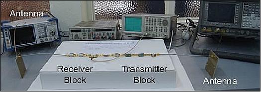
Antenna system
The communication system consists of three subsystems with their backups: the modem, transponder, and the beacon.
System | UHF Antenna (435 MHz) | VHF Antenna (145 MHz) | No of antennas |
Transponder | 2 | 2 | 4 |
Modem | 2 | 2 | 4 |
Beacon | 2 | - | 2 |
Total | 6 | 4 | 10 |
One of the transponders was developed by the RF laboratories of ITU, the second transponder was developed by TAMSAT (Turkish Amateur Satellite Technology Organization). On TurkSat-3USAT the flight model of the TAMSAT transponder is used as primary payload and the engineering model is used as secondary payload.
TurkSat-3USat provides SSB/CW (Single Sideband/Continuous Wave) communications. The Ankara based TAMSAT will also track the TurkSat-3USat. 8)

Camera
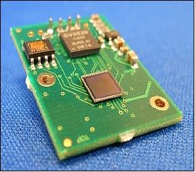
The C329 UART camera module is chosen, due to its size, low power consumption and simplicity. The objective is to take occasional snapshots of target areas. The resolution is VGA and the output is in JPEG picture format. The nanosatellite outer structure features a hole for the lens of the camera module. Position of the top layer is adjusted for the camera module. An UART (Universal Asynchronous Receiver/Transmitter) interface is implemented to control the camera and pass the imagery to the OBC or to the modem. 9)
Deorbiting System
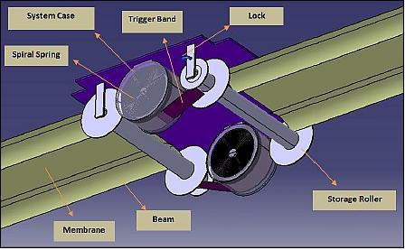
The objective of the deorbiting system is deorbit the nanosatellite within 25 years by increasing the drag force exerted on the nanosatellite by means of enlarging the frontal surface area. The deorbiting system consists of a lightweight thin membrane, supported by band beams, having a curvature which increase the drag force; 2 storage rollers storing the membrane and the band beams; 2 spiral spring systems to deploy the membrane-beam couple, and a lock mechanism to prevent the deployment of the system until the end of satellite’s mission. 10)
The system is being manufactured at the Space Systems Design and Testing Laboratory of the faculty of Aeronautics and Astronautics at ITU.
Working principle: After the completion of the operational satellite mission, two membranes, supported by band beams, will be deployed mechanically against each other. The enlarged cross-sectional area of the deployed membranes in the direction of the velocity vector will cause increased drag for the system - resulting in a quicker deorbiting time of the satellite.
The deorbiting system consists of 4 main components:
1) Membrane – beam couple: Main duty of the membrane – beam couple is to deorbit the satellite with increasing the frontal surface area of the nanosatellite. Kapton HN is selected as membrane material since it has a low density (1.42 g/cm3); its material properties change only slightly in a wide temperature interval (-269 ºC to +400 ºC ). The deorbiting system will carry 2 membrane – beam couples in order to deploy it in reverse sides.
2) Storage unit: The system consists of 2 storage rollers for storing the membrane – beam couple while the deorbiting system is inactive during the operational phase of the mission. The cylinders will be produced from Al-7075 material since it is resistant to space environment.
3) Spiral springs, storage cases and bands: The system consists of 2 spiral springs, their cases and 2 bands. The spiral springs store the required energy for deploying the membrane – beam couple. The bands transmit the required deployment energy from the springs to the storage cylinders. The storage cases conserve the spring - band system and assist the storage of the bands.
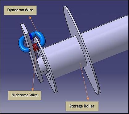
4) Locks: They prevent the deployment of the system before the end of the satellite’s operational mission. The lock mechanism consist of a thin rope called “Dyneemo Wire” and a Nichrome wire so as to cut the rope when a current is applied. Two locks will be allocated to the system.
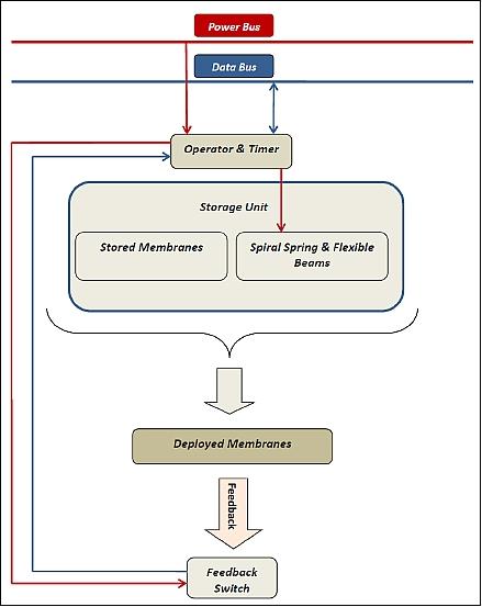
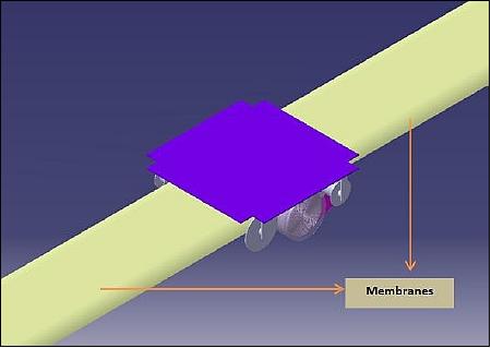
At the end of the operational life of the mission, the deorbiting system of the TurkSat nanosatellite will be activated from the ground station. The deorbiting time foreseen is < 20 years.
References
1) Osman Ceylan, Ramazan Ata, Hasan Bellikli, Hilal Hilye Canbey, Salih Kapicioglu, H. Bulent Yagci6, Rustem Aslan, “VHF – UHF Linear Transponder Design for TURKSAT–3USAT,” 8th IAA (International Academy of Astronautics) Symposium on Small Satellites for Earth Observation, Berlin, Germany, April 4-8, 2011
2) A. Rustem Aslan, Bulent Yagci, Ahmet Sofyali, Murat Suer, Ertan Umit, Osman Ceylan, Bar¿¿ Toktamis, A. Selim Durna, Erdem Akay, Iklim G.Akay, and the ITU NanoSat Group Ibrahim Oz, ¿enol Gulgonul, and the TurkSat NanoSat Group, “TurkSat-3USat: A 3U Communication CubeSat,” Proceedings of the 3rd Nanosatellite Symposium, Kitakyushu, Japan, December 12-14, 2011, paper: NSS-03-0409
3) A. Rüstem Aslan, Rei Kawashima, M. Khalil Ibrahim, “Research and Application Based Space Education,” UN/Japan Nanosatellite Symposium, Nagano, Japan, Oct. 10-13, 2012
4) Murat Suer, Ahmet S. Durna, Galip Celik, Kenan Y. Sanliturk, A. Rustem Aslan, Mehmet Sahin, “Structural Design and Analyses of a 3Unit CubeSat,” Proceedings of RAST 2011 (Recent Advances in Space Technologies) Conference, Istanbul, Turkey, June 9-11, 2011
5) Alim Rustem Aslan, Bulent Yagci, Ertan Umit, Mustafa Erdem Bas, Mehmet Sevket Uludag, Okan Emre Özen, Murat Süer, Ahmet Sofyah, “Lessons Learned developing a 3U Communication CubeSat,” Proceedings of the 64th International Astronautical Congress (IAC 2013), Beijing, China, Sept. 23-27, 2013, paper: IAC-13-D1.5.6
6) “China launches Gaofen-1 satellite,” Xinhua, April 26, 2013, URL: http://www.china.org.cn/china/2013-04/26/content_28668480.htm
7) Rui C. Barbosa, “China back in action with Long March 2D launch of Gaofen-1,” NASA Spaceflight.com, April 25, 2013, URL: http://www.nasaspaceflight.com/2013/04/china-back-in-action-long-march-2d-gaofen-1/
8) http://amsat-uk.org/satellites/non-operational/turksat-3usat/
9) http://www.electronics123.net/amazon/datasheet/C329_UART_data.pdf
10) Ceyhun Tolai, Alim Rustem Aslan, Mustafa Ilarslan, “Development of a Mechanical De-orbiting System for a 3-Unit CubeSat,” Proceedings of the 3rd Nanosatellite Symposium, Kitakyushu, Japan, December 12-14, 2011, paper: NSS-03-0303
The information compiled and edited in this article was provided by Herbert J. Kramer from his documentation of: ”Observation of the Earth and Its Environment: Survey of Missions and Sensors” (Springer Verlag) as well as many other sources after the publication of the 4th edition in 2002. - Comments and corrections to this article are always welcome for further updates (eoportal@symbios.space).