VRSS-1 (Venezuelan Remote Sensing Satellite-1)
EO
Quick facts
Overview
| Mission type | EO |
| Launch date | 29 Sep 2012 |
VRSS-1 (Venezuelan Remote Sensing Satellite-1) / Francisco de Miranda
Overview Spacecraft Launch Mission Status Sensor Complement Ground Segment References
VRSS-1 is Venezuela's first remote sensing satellite. The goal of the VRSS-1 mission is to provide resource studies (high-resolution land and vegetation observations - to assess Venezuela's soil and water resources, collect images to help urban planners, monitor illegal mining and drug activities, and strengthen national defense), support of disaster monitoring.
On May 26, 2011, a contract for the manufacture and launch of the VRSS-1 spacecraft was signed in Caracas, Venezuela, between the government of Venezuela (the Ministry of People's Power for Science, Technology and Intermediate Industries) and CGWIC (China Great Wall Industry Corporation), a subsidiary of CASC (China Aerospace Science & Technology Corporation). 1)
After launch, the VRSS-1 satellite was renamed in honor of Sebastián Francisco de Miranda (1750-1816), a Venezuelan revolutionary hero, known as ‘Generalissimo' Francisco de Miranda, who had planned the independence of the Spanish colonies in South America.
Partner organizations in the VRSS-1 program: ABAE is the Space Agency of Venezuela, subordinated and funded by the Venezuelan Ministry of People's Power for Science, Technology and Innovation (MPPCTI). ABAE is in charge of in-orbit operations, management and application of the VRSS-1 satellite mission. Prior to signing the cooperation agreement of VRSS-1, CGWIC Ltd. had launched Venezuela's first communication satellite, VeneSat-1 on Oct. 29, 2008. VeneSat-1 was renamed to Simón Bolívar-1, in honor of Simón Bolívar, who successfully liberated a vast portion of South America from the Spanish domain. 2)
Note: ABAE (Agencia Bolivariana para Actividades Espaciales) or in English, the "Bolivarian Agency for Space Activities", the name of ABAE signifies the importance of Simón Bolívar to Venezuela) is responsible for developing and carrying out the policies of the National Executive of Venezuela, regarding the peaceful use of outer space. The organization was originally designated as 'Venezuelan Space Center (CEV)', created on November 28, 2005. Later, the requirements grew and the body was renamed to ABAE (Bolivarian Agency for Space Activities). The objective of the ABAE is to design, coordinate and implement the policies of the National Executive, related to the peaceful use of outer space, and to act as a decentralized entity, specializing in aerospace in the country. Since its inception, ABAE has been working on the launch of the first communication satellite of Venezuela, the Simon Bolivar Satellite (VeneSat-1), which was launched on October 29, 2008, and the VRSS-1 satellite, launched September 29, 2012. 3)
The development and construction of the VRSS-1 project in China involved also capacity building for Venezuela, i.e., training of qualified personnel and technology transfer. As part of the technology transfer plan, 52 professionals of ABAE were being trained in CAST Shenzhou Institute (China) in areas such as satellite control and operations, ground station operations and ground application management. 4)
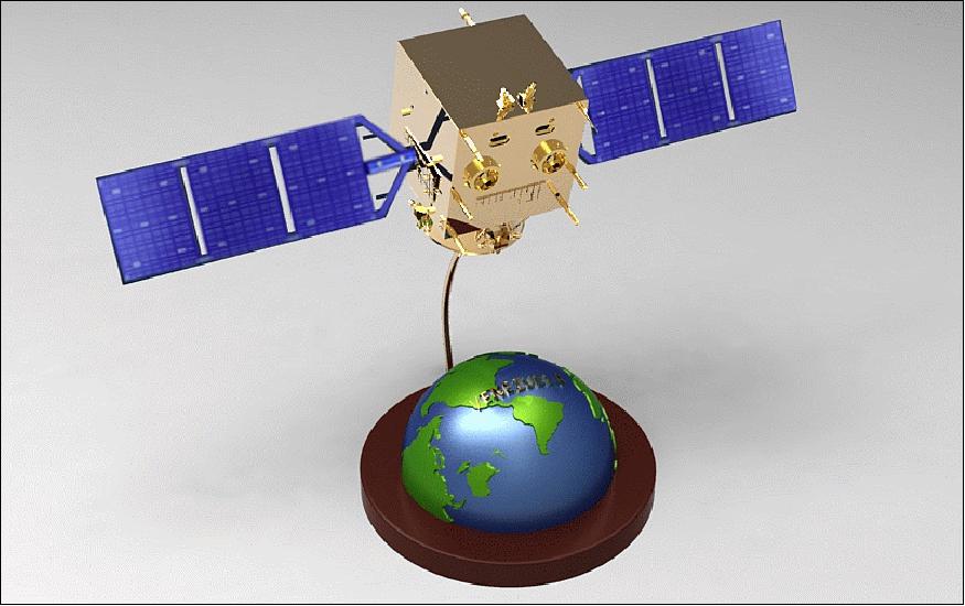
Spacecraft
The spacecraft was designed and developed by DFH Satellite Co. Ltd. of CAST (China Academy of Space Technology) of Beijing, also a subsidiary of CASC, and is being operated by the Venezuela Ministry of People's Power for Science, Technology and Intermediate Industries. The spacecraft is based on the CAST-2000 satellite bus, a compact satellite platform developed for high performance payloads, providing flexibility to host a number of payloads for different applications including remote sensing, communications, and navigation payloads. 5) 6) 7)
The expandable minisatellite bus has a mass of 200 - 400 kg and supports payloads of up to 600 kg. In total, VRSS-1 has a liftoff mass of 880 kg, and the satellite is 1.53 m x 1.65 m x 1.87 m in size (without solar arrays). The spacecraft has two deployable solar arrays for power generation of ~1 k W at the beginning of the mission and ~900 W at EOL (End of Mission). The platform is three-axis stabilized offering a highly precise pointing control; in addition, the CAST-2000 bus provides a large sway maneuver capability. The satellite bus can support different communications systems, including S-band, C-band and X-band or a combination of those. VRSS-1 has an on-orbit design life of 3 years (the service life is estimated to be 5 years).
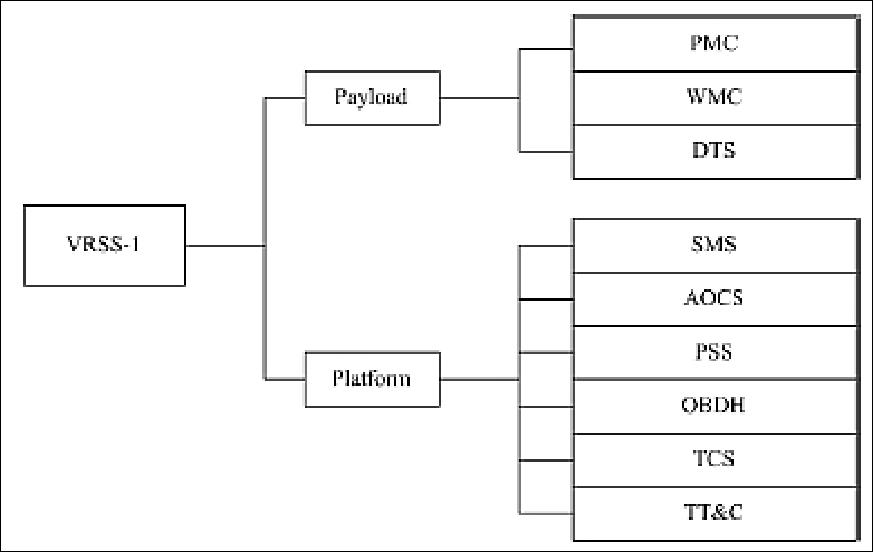
The VRSS-1 satellite consists of two main parts: payload and platform (Figure 2).
The PSS (Power Supply Subsystem) stores, distributes and manages electrical power for all electrical equipment, controlled by the PCU (Power Control Unit) and the PDU (Power Distribution Unit). The GaInP2/GaAs/Ge solar arrays take the job for generating electrical power. In the sunlight, the output power of solar array will meet the satellite operation requirements at first, then meet 55Ah NiCd (Nickel-Cadmium) battery charge power requirement. While in umbra, the battery will discharge and provide power to the equipment.
The SMS (Structure & Mechanism Subsystem) is designed based on the CAST-2000 platform. The satellite consists of three modules: propulsion module, platform module and payloads module. The propulsion module totally inherits the design of the previous CAST-2000 satellites, being composed of the shell, the bracket of the propellant tank, and the bracket pole. The platform and the payload modules are composed of several horizontal and vertical panels to mount the onboard instruments and sustain the load. Each panel features a honeycomb sandwich structure. Two solar arrays are mounted with a biased angle of -10º along the ±Y axis. During flight and after separation, both solar arrays deploy and rotate to follow the sunshine direction.
Spacecraft SMS (Structure & Mechanism Subsystem) | Main body size: 153 cm x 151 cm x 216 cm |
AOCS (Attitude and Orbit Control Subsystem) | Three-axis stabilization |
PSS (Power Supply Subsystem) | Output power of solar array: 1100 W (EOL) |
OBDH (On-Board Data Handling) | Use of CAN bus for TM and TC data |
TCS (Thermal Control Subsystem) | Passive and active thermal control |
TT&C (Telemetry, Tracking & Command) | System: USB (Unified S-Band) +GPS |
Spacecraft mass, service lifetime | 880 kg, 5 years |
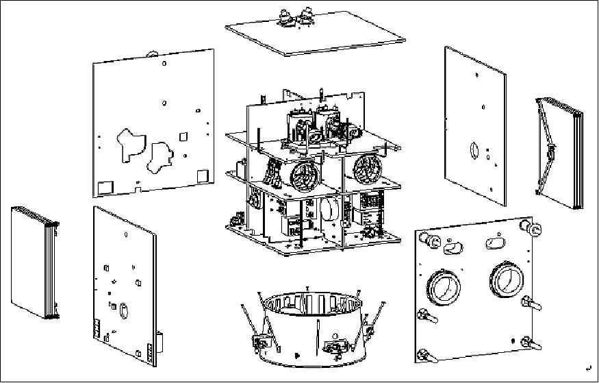
RF communications for VRSS-1 employs an S-band system for TT&C support and an X-band system for data transmissions, the X-band data rate is 190 Mbit/s.
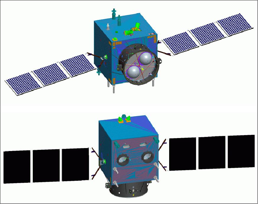
Operational modes: A duty cycle of 10% is used for payload observations. There are four operation modes defined:
- Real-time imaging mode: PMCs and WMCs images when the satellite keeps normal attitude pointing to the ground. In the meantime, DTS may transmit data in real-time.
- Quasi real-time imaging mode: PMCs and WMCs images when the satellite keeps normal attitude pointing to the ground. In the meantime, DTS may transmit data in real-time and records into SSM (Solid State Memory).
- Recording mode: PMCs and WMCs are imaging and the DTS records data, when satellite is inaccessible to any X-band ground station or in roll maneuver status.
- Replay mode: DTS transmits data recorded into the SSM through the X-band antenna to a ground station.
Operational mode | Sunlight/Umbra | Short-term power | Observation time/orbit |
Real-time imaging | Sunlight | 612 W | ≤10 minute |
Quasi real-time imaging | Sunlight | 647 W | ≤10 minute |
Recording | Sunlight | 426 W | ≤10 minute |
Recording | Sunlight | 426 W | ≤10 minute |
Launch
The VRSS-1 satellite ‘Francisco de Miranda' was launched on Sept. 29, 2012 (at 04:12 hours UTC) on a Chinese Long March 2D vehicle (CZ-2D) from the Jiuquan Satellite Launch Center in China. 8)
Orbit: Sun-synchronous near circular orbit, altitude of 625.7 x 662 km (mean altitude of 640 km), inclination = 98º, period = 97.5 minutes, LTDN (Local Time on Descending Node) at 10:30 hours. The revisit time is 4 days.
Mission Status
• The VRSS-1 satellite ‘Francisco de Miranda' and its payload are operating nominally in April 2016. So far, a total of 264,208 images were downlinked and 196.862 images have been cataloged of the Miranda mission, observed in Venezuela, the Caribbean, and South America. Of these images, 179.912 were acquired by PCM (PAN and Multispectral Camera) and 16.950 were acquired by the WMC (Wide-swath Multispectral Camera). 9)

• As of March 13, 2015, a total of 145,513 images are cataloged of the Miranda mission, observed in Venezuela, the Caribbean, and South America, of which 132,466 were acquired by PCM (PAN and Multispectral Camera) and 13,047 were acquired by the WMC (Wide-swath Multispectral Camera). 10)
- Regarding the availability of Miranda satellite images , at present 64,192 images have been cataloged to date, distributed as follows: the PMC has 60,157 images cataloged, and the WMC, has 4,035 cataloged images.
- Since the operation of the Land Application System (SAT) Satellite Miranda in Venezuela, there have been 209,705 images observed, covering passes over Venezuela and elsewhere.
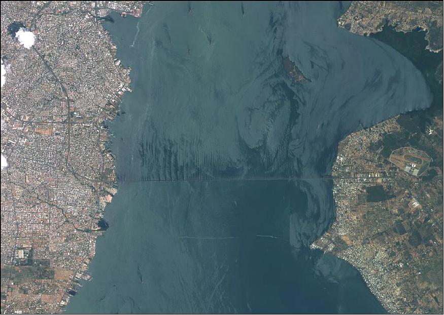
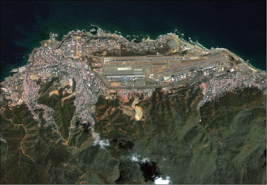
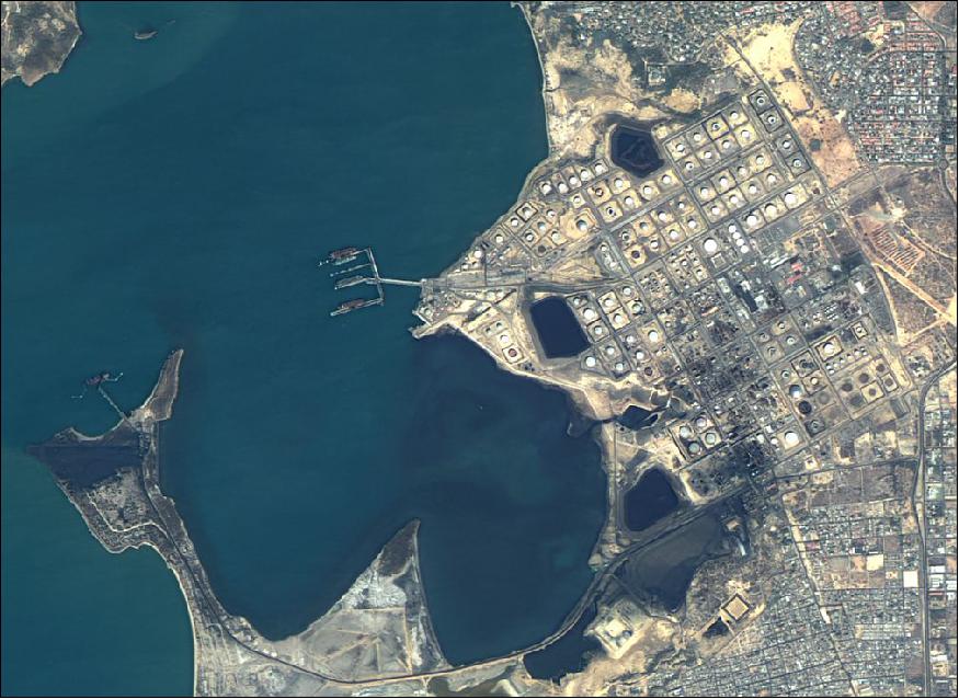
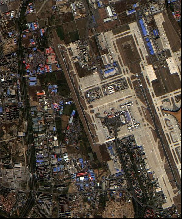
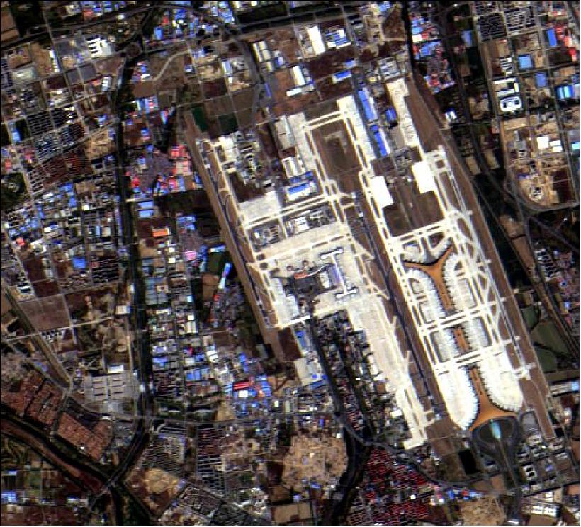
The Miranda spacecraft and its payload are operating nominally in 2015. The following sample images (Figures 7 to 10) were provided by Ref. 10).
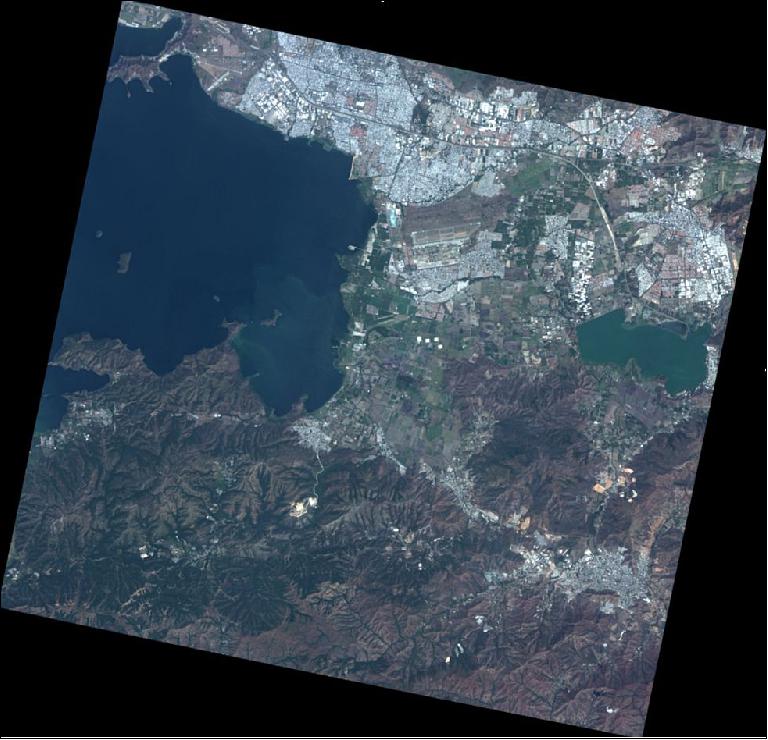
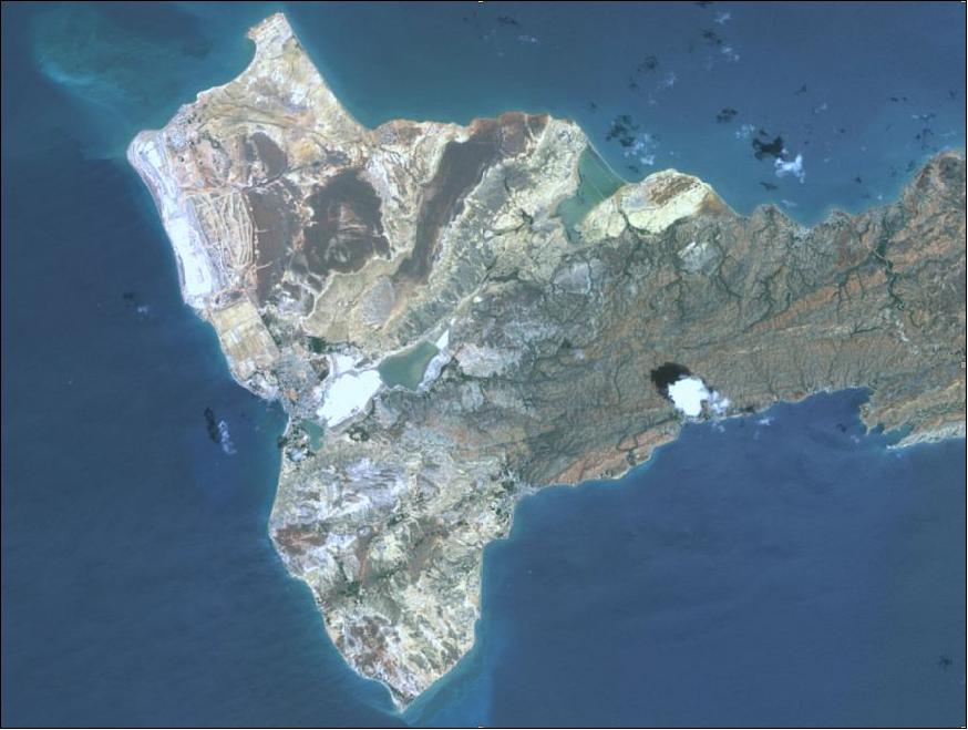
Legend of Figure 10: Araya Peninsula is a peninsula located east of the Caribbean coast of Venezuela in Sucre state. The population of Araya is located at its western end. Araya is arid and dry, is also world famous for its salt mines and has potential for tourism due to its beautiful beaches and the ruins of the old Royal Fortress of Santiago de Arroyo (1630) located on the shores of the beaches.
• In May 2014, the VRSS-1 spacecraft and its payload are operating nominally (Ref. 12).
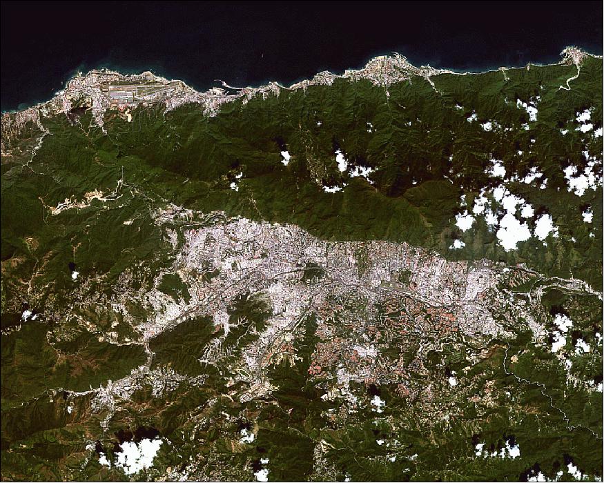
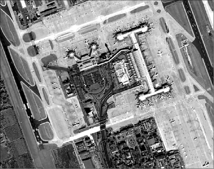
Legend to Figure 11: Caracas (officially Santiago de León de Caracas) is the capital and largest city of Venezuela with a population of 3 million people in the metropolitan region. The Simón Bolívar International Airport, or Maiquetía "Simón Bolívar" International Airport, is clearly visible on the Caribbean coast of Venezuela. The airport is located about 25 km from Caracas.
• In early September 2013, China has delivered full control of the Chinese-built Miranda satellite over to Venezuela. 11)
• The Miranda spacecraft and its payload are operating nominally in July 2013. The project received so far more than 3580 images with a cloud coverage of < 20%. 12) 13)
• On May 31, 2013, VRSS-1 has been on-orbit for more than 8 months; all the subsystems are operating nominally (Ref. 6).
In May 2013, an analysis of the spacecraft health was performed by the DFH project covering the period of the last 8 months. According to the analysis, all equipment was in nominal status.
- All equipment temperatures are stable and maintain a nominal range within bounds.
- The battery can still endure discharge/charge action for the next 5 years.
- No degradation can be detected on the performance of the rotation equipment.
- The thermistor telemetry data from the four cameras remains very stable, which means the quality of the imagery is ensured.
• On October 1, 2012, the two PMC and the two WMC cameras started to take their first images.
Sensor Complement (PMC, WMC)
VRSS-1 is the first Chinese satellite with both high-resolution cameras and wide-swath cameras. There are four cameras, including 18 CCDs, and four X-band data transmission antennae implemented on VRSS-1.
Note: The description of the cameras was provided by Romina Acevedo and the VRSS team of the Bolivarian Agency for Space Activities (ABAE) of Venezuela.
PMC (PAN and Multispectral Camera)
PMC is a high-resolution pushbroom imager (2 cameras) with TDI (Time Delay Integration) capability observing in the visible range at a resolution of 2.5 m in PAN, and of 10 m in MS (Multispectral)mode.
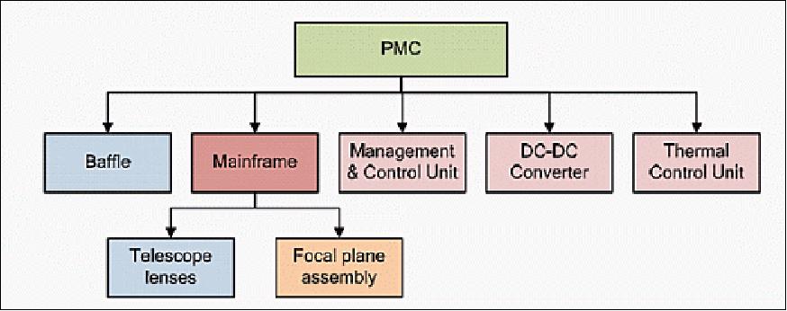
The PMC is composed of two identical camera sets and a thermal control unit which is shared with the WMC. Each camera set includes the camera mainframe, camera management & control unit, DC/DC converter, and the baffle. Each camera comprises lenses and a focal plane assembly. The lenses use a three-mirror reflection aspheric optical system with a focal length of 2.6 m,an aperture diameter of 26 cm, a relative aperture of 1/10, and a FOV (Field of View) angle of 2.7º. A multi-chromatic TDI CCD is used as focal plane receiver in order to solve the lack of the camera input energy. The images of the target object on the camera focal plane are being converted to analog video signals for the different bands through a multi-spectrum TDI CCD. These analog signals are then digitized into 10 bit samples. Finally after synthesizing and inserting image auxiliary data, the digital signals are being send to the data transmission subsystem.
Imager type | Pushbroom with TDI capability |
Spectral bands | PAN: 0.45-0.90 µm |
GSD (Ground Sample Distance) at nadir | PAN: ≤2.5 m |
Swath width at nadir | ~57 km |
Detector CCD | Pan: 10µm x 10µm, pixels ≥12,000 (single camera) |
MTF (Modulation Transfer Function) | ≥0.18(PAN), ≥0.2(MS) |
SNR (Signal to Noise Ratio) | PAN: ≥48 dB (solar zenith angle =70º, surface albedo =0.65) |
Data quantization | 10 bit |
Instrument mass | 135 kg |
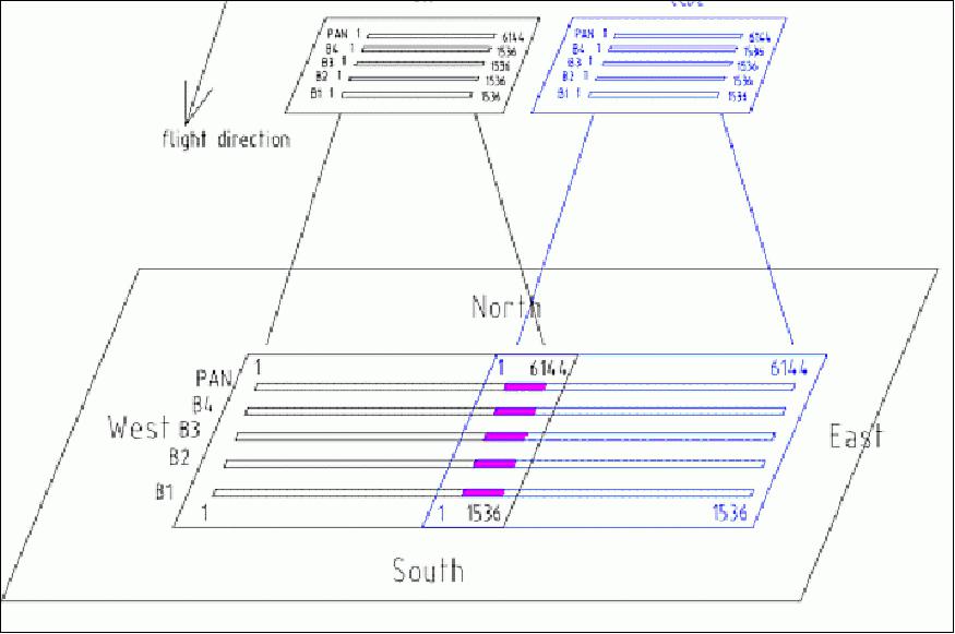
To meet the requirement of the 57 km swath width coverage, two PMCs are mounted side by side to form a total FOV of 5.15º with the FOV overlap of about 0.1º.
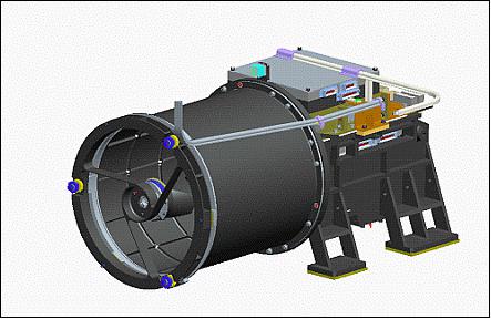
The PMC mainframe is composed of the telescope lenses and the FPA (Focal Plane Assembly), including the joint assembly and the electronic assembly as shown in Figure 17. The cylindrical portion of the telescope employs a composite structure for better stiffness and a small thermal expansion coefficient.
The secondary mirror unit is supported by a tangential tripod in order to enhance the structural stiffness and the thermal stability. The main frame of the black body assembly of the telescope lens is the primary load-carrying structure to support the front body unit and focal plane assembly (use of a titanium alloy). The main frame has support arms used to be connected with the spacecraft structure. The focusing mechanism is located in the black body calibration unit, it can perform focusing using the control of manager.
The management & control unit is in charge of the camera control and parameter adjustment. It receives the camera focusing instructions through a CAN bus, and controls the adjustment of the camera FPA; it receives the instructions of integration time codes, integration stages setup and gain set-up and forwards them to the FPA in order to control the circuit switch between the main and the spare unit.
The DC/DC converter is used to provide various electric sources for the TDI CCD devices and the FPA. It converts the primary power required by the two TDI CCDs and the FPA, and controls the circuit power-on according to the specified time sequences. The DC/DC converter has the ability to limit the current to protect the electronic assembly.
TCU (Thermal Control Unit): The thermal control unit can actively control the temperature of the two PMCs and the two WMCs to maintain a constant thermal environment. This unit consists of multi-layer heat-insulated blankets, heating circuits, temperature sensors and controlling circuits. Passive as well as active temperature control features have been implemented for an effective PMC temperature control. The active temperature control is executed through the TCU, and the approach of controlling is by heating. The camera is coated on the outside by a multilayer heat insulation material; the metal parts inside are surface blackened. Electric heating is used for the active temperature control to ensure temperature stability of each camera lens. An insulation design is adopted to implement thermal isolation for the satellite load equipment cabin. The thermal insulating GFRP (Glass Fiber Reinforced Polymer) pad is mounted between the camera installation seat and the payload module panel to reduce the coupling thermal effect between the satellite body and the camera body, which could isolate the changes of space heat flux under the condition of the payload module temperature environment so that the camera temperature could be slightly affected. Therefore, the camera active temperature control power can be adjusted to satisfy the temperature control requirements.
WMC (Wide-swath Multispectral Camera)
WMC is a medium-resolution pushbroom camera set (2 cameras) with TDI (Time Delay Integration) capability observing in the visible range at a spatial resolution of 16 m in MS mode. WMC is composed of two mainframes, one camera management & control unit; each camera set includes a mounting bracket, a baffle and a thermal control unit shared with the PMC.
WMC is a refractive optical system with the beam splitting prism, which divides the incident light into 4 spectral bands onto 4 CCD devices, located at the FPA. After the photoelectric conversion, the detectors output signals are processed by signal processing circuit, and transmitted to the ground through the DTS (Data Transfer System).

Imager type | Pushbroom with TDI capability |
Spectral bands | B1/blue: 0.45-0.52 µm |
GSD (Ground Sample Distance) at nadir | ≤16 m |
Swath width at nadir | ~370 km |
Detector | CCD, 12,000 pixels of size 6.5 µm |
Optical system | Refractive optical system, focal length = 270 mm |
MTF (Modulation Transfer Function) | ≥0.14(B4), ≥0.2(other bands) |
SNR (Signal to Noise Ratio) | MS: ≥20 dB (solar zenith angle =15º, surface albedo =0.05) |
Data quantization | 10 bit |
Instrument mass | 75 kg |
Optical system: A refractive optical system with a focal length of 270 mm, relative aperture of 1/3.5, and FOV of 16.44º is selected to satisfy the requirements of ground imaging swath and ground resolution. The CCD pixel size is 6.5 µm corresponding to a Nyquist frequency of 77 lp/mm. The primary optical lens of the WMC uses a rear telecentric optical path configuration. This type of optical system has advantages of (1) small spectral shift for the accuracy of spectrum localization; (2) the principal ray being perpendicular (or almost) to the field for minimum band error registration.
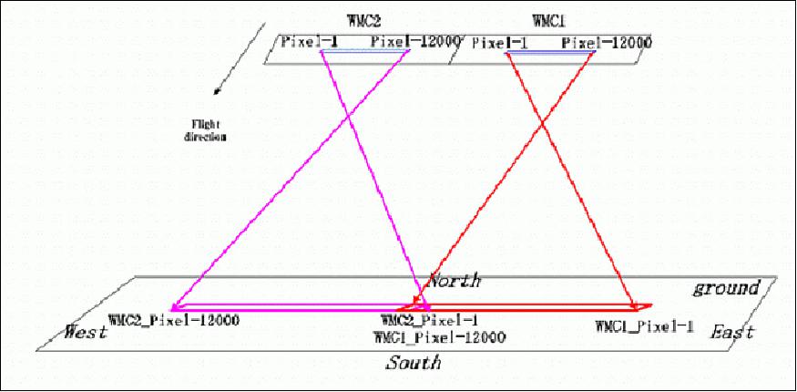
Each CCD has a size of 12,000 pixels. With a FOV of 16.44º and a nadir resolution of15.4 m, the corresponding swath width is 184.8 km from a mean altitude of 640 km. The two WMCs have a cumulative swath of ~373 km with an overlap of 0.5º.
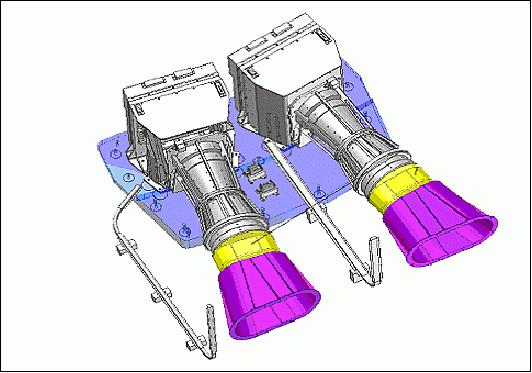
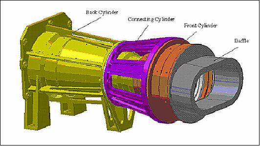
The WMC mainframe is composed of two cameras, each equipped with its own set of video processing capability (Figure 20). The optical system of WMC uses a projection-type lens arrangement. The system features front and back parts, which are mounted in the front and back cylinders, respectively, and joined by a connecting cylinder (Figure 21).
Ground Segment
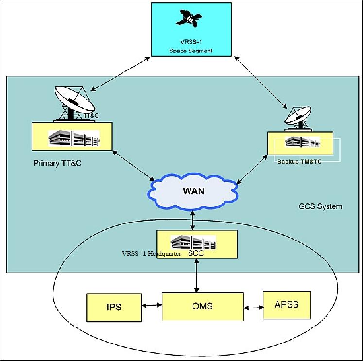
According to contract, the China Satellite Launch and Control Systems Division is responsible for the development of the Baemari station in Venezuela along with a ground control OMS (Operations Management System), the system includes the master control station, an alternate (backup) control station, and the SCC (Satellite Control Center). The SCC is responsible for the monitoring and control of the spacecraft, for the acquisition, archiving and processing of the payload data, and for the preparation of the satellite operations and control schedules at OMS. 14)
1) "Venezuelan Remote Sensing Satellite (VRSS-1)," CGWIC (China Great Wall Industry Corporation), URL: http://cn.cgwic.com/VRSS-1/english/satellite.html
2) "Partners," CGWIC, URL: http://cn.cgwic.com/VRSS-1/english/partner.html
3) R. Acevedo, R. Becerra, N. Orihuela, F. Varela, "Space activities in the Bolivarian Republic of Venezuela," Space Policy (Elsevier), Volume 27, Issue 3, August 2011, pp: 174–179
4) R. Hernandez, R. Acevedo, F. Varela, S. Otero, "Current Space Projects of the Bolivarian Republic Venezuela," RevMexAA (Serie de Conferencias), Vol. 43, pp:9–12 , 2013
5) "China launches first Venezuelan Remote Sensing Satellite via CZ-2D," Spaceflight 101, Sept. 29, 2012, URL: http://www.spaceflight101.com/long-march-2d-vrss-1-launch.html
6) Yan Cheng, Zhizhuang Li , Hongzhi Zhao, Shuyan Wang, Yufu Cui, Jian Zhao, "VRSS-1 Satellite Summary," Proceedings of the 64th International Astronautical Congress (IAC 2013), Beijing, China, Sept. 23-27, 2013, paper: IAC-13-B4.1.7
7) "Focus," CGWIC, 2012, URL: http://cn.cgwic.com/VRSS-1/english/focus.html#
8) Rui C. Barbosa, "Chinese Long March 2D launches Venezuela's VRSS-1 satellite," NASA Spaceflight.com, Sept. 28, 2012, URL: http://www.nasaspaceflight.com/2012/09/chinese-long-march-2d-launches-vrss-1/
9) Information provided by Raúl Hernández, Director of Space Applications of ABAE, Caracas, Venezuela.
10) Information received from Romina Acevedo, Chief coordinator, Department of International Affairs of ABAE, Caracas, Venezuela.
11) "China delivers control of satellite to Venezuela," Space Daily, Sept. 09, 2013, URL: http://www.spacedaily.com/reports/China_delivers_control_of_satellite_to_Venezuela_999.html
12) Information received from Romina Acevedo, Chief coordinator, Department of International Affairs of ABAE, Caracas, Venezuela.
13) "Satélite Miranda (VRSS-1)," in Spanish, URL: http://www.mcti.gob.ve/Satelites/Miranda
14) "Ground Telemetry & Control," URL: http://cn.cgwic.com/VRSS-1/english/cekong.html
The information compiled and edited in this article was provided by Herbert J. Kramer from his documentation of: "Observation of the Earth and Its Environment: Survey of Missions and Sensors" (Springer Verlag) as well as many other sources after the publication of the 4th edition in 2002. - Comments and corrections to this article are always welcome for further updates (eoportal@symbios.space)
Overview Spacecraft Launch Mission Status Sensor Complement Ground Segment References Back to Top