AISat (Automatic Identification System Nanosatellite)
EO
Mission complete
DLR
Automatic Identification System Nanosatellite (AISat) is a technology demonstration mission of the German Aerospace Center (DLR) that launched in June 2014. The mission aims to demonstrate maritime traffic navigation with improved antenna directionality compared to existing AIS satellites.
Quick facts
Overview
| Mission type | EO |
| Agency | DLR |
| Mission status | Mission complete |
| Launch date | 30 Jun 2014 |
| End of life date | 30 Jun 2019 |
| CEOS EO Handbook | See AISat (Automatic Identification System Nanosatellite) summary |
Summary
Mission Capabilities
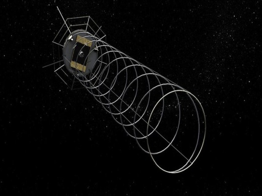
AISat features a large helical antenna with a high directional sensitivity for AIS signal collection. AIS is a radio system used for collection of navigation, position and identification data of maritime traffic, and a helical antenna allows for the focussed illumination of a small area. AISat can receive Class-A and Class-B signals as well as the Rescue Transmitter signal of rescue craft and vessels in distress. AIS data is stored onboard and downlinked to ground stations for processing and distribution.
Performance Specifications
Helical antennas are ideal for transmitting and receiving circularly polarised electromagnetic waves, and they have excellent directionality. Their gain increases with the number of windings, and they can receive a narrow footprint of AIS data in order to trace individual ships’ data. AISat’s fiber-composite helical antenna measures 4 m in length and 0.57 m in diameter when deployed. The antenna was stored in a coil for launch, and was deployed like a spring as it unfolded its windings.
AISat was launched as a secondary payload into a Sun-synchronous orbit of altitude approximately 600 km, inclined at 98.2°.
Space and Hardware Components
AISat is based on DLR’s CLAVIS satellite bus, which was developed to provide a cost-effective satellite platform with easy integration using commercial CubeSat components. Attitude determination is enabled by solar cells as Sun sensors, a three-axis magnetometer and a three-axis gyroscope unit. AISat will be stabilised by a gravity-gradient created by the deployed helical antenna. The satellite communicates with a Ultra-High Frequency (UHF) system, in which a UHF transceiver and two monopole antennas with omnidirectional coverage are used for Telemetry, Tracking and Command (TT&C).
AISat (Automatic Identification System Nanosatellite)
AISat is technology demonstration mission of DLR (German Aerospace Center). Two institutes of DLR are involved in the development of this project: The Institute of Space Systems in Bremen developed the main body of the nanosatellite and system engineering, while the Institute of Composite Structures and Adaptive Systems in Braunschweig took the responsibility for the experimental verification of the helical antenna. Cooperating partners in the project are the University of Bremen and two industrial companies.
The distinctive feature of this mission, compared to AIS (Automatic Identification System) satellites already in orbit, lies in the use of a high-gain helical antenna, which enables the reception of AIS signals, especially on highly frequented sea areas, where signal collisions often lead to non-decodable data.
The mission objectives require an antenna with an excellent directionality, i.e. with a comparatively narrow illumination radius. Otherwise, with a too large antenna footprint the satellite would receive a huge amount of signals from a very large area. Moreover, many interfering signals which are present in adjacent frequency bands would make it almost impossible to trace individual ships. High-gain helical antennas have the required directionality – and they are able to receive not only the Class A VHF signals from commercial shipping, but also Class B signals from non-commercial ships, as well as Search And Rescue (SAR) transmitter signals sent from survival craft or distressed vessels. Thus, the spiral form of the antenna was mandatory. 1) 2) 3) 4) 5) 6)
Spacecraft
AISat is a suitcase-sized nanosatellite with a deployable fiber-composite antenna. The antenna is stowed within a small volume for launch, only to extend to its operational dimensions once released in orbit.
AISat is based on the CLAVIS satellite bus that itself is based on the PC/104 CubeSat platform. The bus was developed by the German Aerospace Center to provide a cost-effective satellite platform that requires little man power for integration using commercially available CubeSat components. CLAVIS was designed to be able to host different payload types with high flexibility using a defined mechanical interface and a unified electrical and data interface. 7) 8)
The satellite bus uses a quad-stack configuration made up of the PC/104 cubesat boards with a back plane that connects the individual boards and also provides the data and electrical interface for the payload. CLAVIS uses body-mounted solar cells for power generation – five panels each, consisting of 12 GaAs cells, are installed on five side panels of the spacecraft to generate up to 15 W of power that is fed to a PCDU (Power Conditioning and Distribution Unit) which controls the state of charge of a 40 Wh battery pack and distributes power to all satellite subsystems. The spacecraft uses 3.3 V, 5 V and 12 V power buses. A switching board adds switching functionality to the power system and provides bus protection.
The spacecraft uses an ARM7 processor as the centerpiece of the OBC (OnBoard Computer) connected to the CAN and PC data buses as well as analog lines to control the attitude control system. The OBC includes 2 MB of SRAM and 2 x 4 MB of flash memory for avionics software and mission data. Attitude determination is accomplished through the use of the solar cells as sun sensors, a three-axis magnetometer and a three-axis gyro unit. AISat features three magnetic torquers for attitude actuation, but the satellite will be stabilized through a gravity-gradient generated once the large antenna is deployed.
RF communications: The satellite uses a UHF communications system. A UHF transceiver and two monopole antennas with omnidirectional coverage are used for telemetry downlink and command uplink.
Launch
AISat was launched as a secondary payload on June 30, 2014 on the PSLV-C23 vehicle of ISRO from SDSC (Satish Dhawan Space Center), Sriharikota, India. The primary payload on this flight was SPOT-7, a commercial imaging mission of Airbus Defence and Space. 9) 10) 11)
Orbit: Sun-synchronous orbit, altitude of ~660 km, inclination = inclination = 98.2º.
The secondary payloads on this flight were:
• CanX-4 and CanX-5, a pair of identical nanosatellites (each of 15 kg) of UTIAS/SFL (University of Toronto, Institute for Aerospace Studies/Space Flight Laboratory), Toronto, Canada
• AISAT (Automatic Identification System Satellite), a technology demonstration nanosatellite (14 kg) of DLR (German Aerospace Center).
• VELOX-1 is a 3U CubeSat with a mass of 4.5 kg of SaRC (Satellite Research Center) at NTU (Nanyang Technological University), Singapore.
Mission Status
• Sept. 4, 2014: The first things the AISat satellite caught sight of were the Russian Kamchatka Peninsula and the Bering Sea – but at that time only one non-directional rod antenna was in use on board the satellite. Within eight minutes, the receiver picked up AIS (Automatic Identification System) signals from 45 ships. The 4 m helical antenna deployed and was brought into operation on 8 August 2014. Since then, orbiting at an altitude of 660 km, the helical and non-directional rod antennas have captured over 52,000 datasets. This was a first, because an axial helical antenna had never before been used to detect ships. 12)
- The DLR researchers are satisfied – although the satellite pointing is not yet completely correct. Some parameters for the attitude control system still need to be optimized before the satellite's orientation can be stabilized. The researchers are hopeful that the helical antenna will soon allow greater accuracy in the reception of ship signals, which provide information on position, vessel size and cargo from areas with heavy maritime traffic.
- Listening to each individual ship signal: Non-directional rod antennas used until now, have tended to become overwhelmed by large numbers of AIS signals, especially in regions with heavy shipping traffic — they observe footprints with a diameter of about 5000 km and receive too many simultaneous messages to be able to assign the signals to individual vessels. The AISAT helical antenna targets a footprint of just 750 km in diameter, resulting in correspondingly fewer AIS signals. It is expected, that the smaller observation footprint will enable the project to detect individual ship signals with greater precision. This will help improve safety in areas such as the Mediterranean, the North Atlantic coast of America and major ports such as those of Beijing, Tokyo and Singapore.
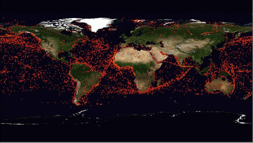
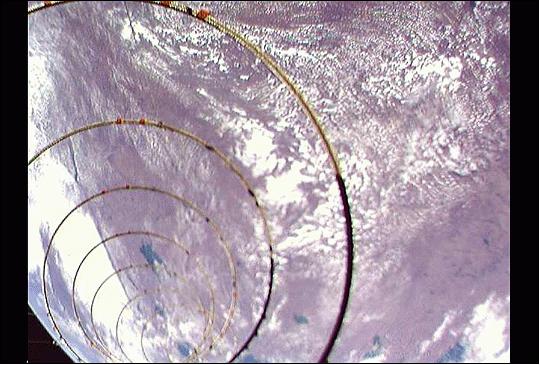
Legend to Figure 8: The camera on board the AISAT acquired this first image of the deployed helical antenna. With the 4 m helical antenna, ship AIS signals can be received with greater precision than when using non-directional rod antennas.
• The AISat nanosatellite was injected into an orbit of 660 km altitude according to plan, 1113.7 seconds after liftoff. At 8:30 GMT on June 30, the first signal from the satellite reached the control room at the DLR Institute of Space Systems. During the first flight over Bremen, the DLR researchers had six minutes of contact with the satellite at 10:05 GMT. One and a half hours later, they were able to keep contact with and download data from AISat for seven minutes (Ref. 9).
Once it has been established that the satellite has survived the mechanical loads it experienced during the launch and its orientation has stabilized, the DLR researchers will send the command to deploy the 4 m long helical antenna.
Sensor Complement
AIS (Automatic Identification System) Receiver
AIS is a radio system designed for the collection of navigation, position and identification data from each and every vessel, to make global maritime traffic safer and easier to control. The AIS assembly employs an innovative antenna concept which has been developed for this project.
AISat features a large helical antenna to take a new approach to AIS signal collection. Helical antennas are suited for transmitting and receiving circularly polarized signals and provide a high directional sensitivity. Their gain characteristics are excellent and increase with the number of windings. Using a high-gain antenna allows for a narrow aperture that only illuminates a very small footprint on the ground. The drawback of a helical antenna is the requirement of a conducting plate on its mounting interface acting as a reflector.
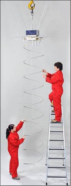
The AISat helical antenna measures 4 m in length and 0.57m in diameter when deployed featuring a little over eight windings. It launches in a spring-loaded fashion that is released after spacecraft separation. The deployment is controlled by thin retracting cords that stop the antenna once it reaches its fully deployed position, preventing it from extending further due to the spring force.
The antenna consists of a core using cylindrical sandwich struts and a fiber fabric hose to provide stability – the hose surrounds an inner core made of hard foam. The core is surrounded by thinned copper wires forming a metallic fabric tube. The control rods are electric isolators and ensure a stable self-deployment of the antenna within a reasonable timeframe.
Using the helical antenna, AISat can receive Class-A and Class-B AIS signals and the AIS Search and Rescue Transmitter signal of rescue craft and vessels in distress. AIS data is stored onboard and downlinked to ground stations for processing and distribution.
Some background: Helical antennas offer some outstanding properties in comparison with other types of antennas: They are ideally suited for transmitting and receiving circularly polarized electromagnetic waves, and they have an excellent directionality. Their gain increases with the number of windings, at least up to 7 or 8 windings. The higher the achievable gain, the narrower becomes the angle of aperture. On their backside helical antennas need a conductive plate which acts as reflector. 13)
The AISat helix antenna is made of a sandwich strut consisting of a hard foam core and a braided fiber composite sleeving as depicted in Figure 9. The length of the antenna is controlled by means of three flexible control cords. These are braided glass-fiber cords with a diameter of 1 mm made from SILTEX E-glass material (Figure 11). Since fiber composites, are bad electric conductors the strut is additionally covered with a metal fabric.
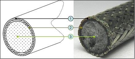
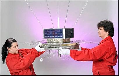
In the manufacturing process of the helix wire a (carbon/aramid)-fiber braided sleeving (Figure 9, item 2) is pulled over a cylindrical hard foam core (Figure 9, item 3). The fibers are impregnated with epoxy resin and then surrounded with a thin heat shrink tube. This process is almost identical with the well-proven manufacturing process of straight pultruted carbonfiber struts, apart from two differences:
1) The shrinkage hose consists of PE (polyethylene) instead of glassfibers.
2) There are no unidirectional fibers in longitudinal direction, because they would inevitably tend to buckle on the inner side of the windings (which cannot occur on straight struts).
Another reason for the usage of a braided fabric sleeving without unidirectional fibers lies in the fact that the helix will be stowed like a spiral spring. In order to reach a high spring stiffness in a spiral spring, the shear modulus is the most critical material parameter due to slight torsion during spring compression.
To ensure a high capability of bearing shear loads induced by torsion the fabric hose consists of rovings which are oriented at angles of ±45º when applied to a strut with nominal diameter. In case of the helical antenna with diameters between 8.5 mm and 9.5 mm angular orientations of about ±30º could be achieved.
The CFRP (Carbon Fiber Reinforced Plastic) helix wire is made of a Torayca T300 braided sleeving from SILTEX. The fibers of the helix with an aramid braided sleeving are conventional aramid fibers which have not been distinctively identified by the sleeving manufacturer SILTEX.
Parabolic Flight Campaign
The helical antenna is a so-called “gossamer” structure, with a length of 4 m when deployed, which required testing in zero-g conditions of the release function to monitor the self-deployment of the structure and to verify its proper alignment.
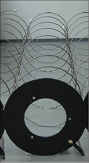
As listed in Table 1, the helix structures P1 and P3 are made from CFRP with a GFRP (Glass Fiber Reinforced Plastic) inlet. Both structures vary in cross section with P1 having a 8.5 mm wire diameter and P3 having a 9.5 mm diameter. P2 and P4 are completely made of aramid fiber reinforced plastic with P2 having 8.5 mm diameter and P4 having a 9.5 mm diameter. The GFRP inlet for P1 and P3, on which the helix structure is fixed to the reflector plate, had to be withdrawn since CFRP is slightly electrically conductive. If the whole structure had been made from CFRP, a weak electrical link between the end of the metal fabric hose and the reflector plate would be possible but would lead to gain losses or even to a short circuit.
Parabola sequence | Label | Material | Wire diameter | Mass (kg) | Prestressed length |
1 | P1 | CFRP/GFRP | 8.5 mm | 0.86 | 4.0 m |
2 | P2 | Aramid | 8.5 mm | 0.73 | 4.0 m |
3 | P3 | CFRP/GFRP | 9.5 mm | 0.92 | 4.0 m |
4 | P4 | Aramid | 9.5 mm | 0.88 | 4.0 m |
5 | P5 | CFRP/GFRP | 8.5 mm | 0.86 | 3.5 m |
6 | Photographic documentation | ||||
Table 1: Parameters and test sequence of the test structures
Test rack: The helix structures were stored in stowed configuration in a magazine box on the test rack. For each test series (5 parabolas) one of them was taken out and locked in vertical position on a triangular interface plate with integrated force transducers so that the reaction forces upon deployment could be measured (Fig. 13). The measurement equipment consists of:
- three 3-axial preloaded force transducers
- three charge amplifiers
- two dynamic signal analysers
- one laptop with data acquisition software.
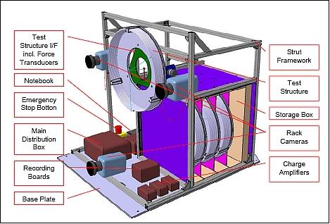
Four slightly different AISat antenna types were tested in the course of the 15th DLR Parabolic Flight Campaign in Bordeaux (France) on March 9, 2010. The antennas were stored in their stowed configuration in a test rack magazine. For each test series (5 parabolas) one of them was taken out and locked onto a circular antenna ground plate (a sandwich plate) in vertical position (Figure 13). Once released, the antennas should safely unfold up to a total length of ~ 4 m, with a helix diameter of 0.57 m.
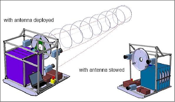
The spring unfolding behavior was recorded with 3 video cameras fastened on the test rack and two additional cameras mounted on the aircraft handrail behind and in front of the test rack. All cameras were self-recording. They were switched on prior the first parabola and switched off after the last parabola. In order to be able to correlate the aircraft zero-g data with the test results the clock of the recording laptop and the system clock of the aircraft were synchronized. To correlate the movie material recorded by the video cameras the trigger signal for the start of the recording of the force transducer data has been used to give a light signal to all cameras.
The following conclusions can be drawn from the test flights:
- The concept of a helical antenna which can be stowed and then, upon release, expand like a compression spring, is feasible.
- With a stiffness reserve that is large enough to compensate losses induced by material creep and relaxation, and with suited control cords which limit the expansion, the helices will achieve a stable final length which can be adjusted in accordance with the electromagnetic requirements.
- The direction into which the antenna moves forward immediately after release depends strongly on the uniformity of its interaction with the release mechanisms. High-quality release mechanisms with little friction will help to make the expansion as straight as possible.
- The vibrations induced by the expansion and, in particular, by rebounds of the antenna tip when the control cords are tightened, damping with time; although there was not sufficient time during the zero-g phases to reduce the vibrations completely.
- The overall performance of carbonfiber-based antenna cores is superior to competing types. Consequently the AISat flight model will be equipped with such an antenna.
References
1) “A Helical Antenna for AISat – Self-Deploying and Self-Aligning,” Innovation Report 2010, DLR, pp. 22-23, URL: http://www.dlr.de/.../Innovationsbericht_2010_fuers_Internet.pdf
2) Joachim Block, A. Bäger, J. Behrens, T. Delovski, L.-C. Hauer, M. Schütze, R. Schütze, T. Spröwitz, “A Self-Deploying and Self-Stabilizing Helical Antenna for Small Satellites,” Proceedings of the 61st IAC (International Astronautical Congress), Prague, Czech Republic, Sept. 27-Oct. 1, 2010, IAC-10.C2.2.2
3) http://www.dlr.de/irs/en/desktopdefault.aspx/tabid-6970/11520_read-26880/
4) Falk Nohka, Martin Drobczyk, Ansgar Heidecker, “Experiences in Combining Cubesat Hardware and Commercial Components from Different Manufacturers in order to build the Nano Satellite AlSAT/CLAVIS-1,” Proceedings of the 4S (Small Satellites Systems and Services) Symposium, Portoroz, Slovenia, June 4-8, 2012
5) Martin Drobczyk, Muhammad Bassam, Alexander Lange, Falk Nohka, Joachim Strenge, “Design and Implementation of a TM/TC Software System of the Nano Satellite AlSAT/CLAVIS-1,” Proceedings of the 4S (Small Satellites Systems and Services) Symposium, Portoroz, Slovenia, June 4-8, 2012
6) Andis Dembovskis, “Testbed for Performance Evaluation of SAT-AIS Receivers,” 6th ASMS (Advanced Satellite Multimedia Systems Conference) and 12th SPSC (Signal Processing for Space Communications Workshop), Baiona, Spain, Sept. 5-7, 2012, URL: http://elib.dlr.de/80710/1/my.06333085.pdf
7) Falk Nohka, Martin Drobczyk, Ansgar Heidecker, “Experiences in Combining Cubesat Hardware and Commercial Components from Different Manufacturers in order to build the Nano Satellite AISat/Clavis-1,” Proceedings of the 26th Annual AIAA/USU Conference on Small Satellites, Logan, Utah, USA, August 13-16, 2012, paper: SSC12-XI-8, URL: http://digitalcommons.usu.edu/cgi/viewcontent.cgi?article=1094&context=smallsat
8) “Nano-Satellite CLAVIS," DLR, URL: http://www.dlr.de/irs/en/desktopdefault.aspx/tabid-7206/11991_read-28510/
9) “AISat satellite transmits from space,” DLR, June 30, 2014, URL: http://www.dlr.de/dlr/en/desktopdefault.aspx/tabid-10081/151_read-10812/year-all/#/gallery/15477
10) Patrick Blau, “India's PSLV Rocket successfully delivers SPOT-7 & Small Satellites to Orbit,” Spaceflight 101, June 30, 2014, URL: http://www.spaceflight101.com/pslv-c23---spot7-launch-updates.html
11) “PSLV-C23 brochure,” ISRO, URL: http://www.isro.org/pslv-c23/pdf/pslv-c23-brochure.pdf
12) Manuela Braun, Jörg Behrens, “AISat – over 52,000 ship signals received from around the world,” DLR, Sept. 4, 2014, URL: http://www.dlr.de/dlr/en/desktopdefault.aspx/tabid-10081/151_read-11383/year-all/#/gallery/16202
13) Tom Sproewitz, Joachim Block, Annette Bäger, Lars Hauer, Martin Schuetze, “Deployment Verification of Large CFRP Helical High-Gain Antenna for AIS Signals,” 2011 IEEE Aerospace Conference, Big Sky, MT, USA, March 5-12, 2011
The information compiled and edited in this article was provided by Herbert J. Kramer from his documentation of: "Observation of the Earth and Its Environment: Survey of Missions and Sensors" (Springer Verlag) as well as many other sources after the publication of the 4th edition in 2002. - Comments and corrections to this article are always welcome for further updates (eoportal@symbios.space).