AISSat-1 and 2
EO
Operational (extended)
Communications
AIS
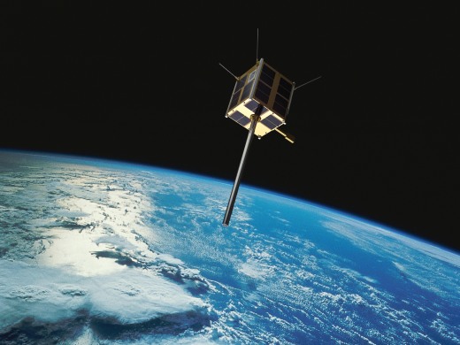
Automatic Identification System Satellite -1 and -2 (AISSat-1 and -2) are identical nanosatellites, owned and operated by the Norwegian Space Agency (NOSA), Launched in July 2010 and July 2014 respectively. The AISSat constellation aims to improve the maritime safety and efficiency of navigation, safety of life at sea and the protection of the marine environment. AISSat-1 left service in June 2022, while AISSat-2 is still operational.
Quick facts
Overview
| Mission type | EO |
| Agency | NOSA |
| Mission status | Operational (extended) |
| Launch date | 12 Jul 2010 |
| Instruments | AIS |
| Instrument type | Communications |
| CEOS EO Handbook | See AISSat-1 and 2 summary |
Summary
Mission Capabilities
Both AISSat-1 and -2 carried a single instrument, the AIS receiver (ASR 100). ASR 100 has been designed and developed by Kongsberg Seatex AS (KSX), and is a self-organising, Time Division Multiple Access (TDMA) radio communication system. It aims to provide identification and location services for the tracking of maritime systems.
Performance Specifications
The AIS sensor is essentially a dual channel VHF (Very High Frequency) receiver. As such, it can be tuned to any channel in the maritime VHF bands, ranging 156,025 MHz - 162,025 MHz.
AISSat-1 operated in a sun-synchronous orbit with an altitude of 624 km, and inclination of 98.1°, with a period of 97 minutes. AISSat-2 operates in a sun-synchronous orbit of altitude 628 km, inclination 98.4° and a period of 97 minutes.
Space and Hardware Components
AISSat-1 and -2 used identical buses, based on the Generic Nanosatellite Bus (GNB) design, of University of Toronto, Institute for Aerospace Studies/Space Flight Laboratory (UTIAS/SFL), and have been constructed by UTIAS/SFL on behalf of NOSA. The GNB bus is a cube with side lengths of 0.2 m and a launch mass of approximately 6.5 kg. The bus houses the satellite subsystems, the electrical power subsystem (EPS) and attitude determination and control subsystem (ADCS). EPS is a dual battery, gallium arsenide triple-junction solar cell based power system, including peak power tracking capabilities, with the cells having a BOL (Beginning of Life) efficiency of 26.8%, delivering up to 967 mW at their peak power point at 28ºC. ADCS a full 3-axis ADCS with a fine pointing capability, with attitude sensing provided by six sun sensors, three rate gyros and a magnetometer, while actuation is provided by three orthogonally mounted reaction wheels.
AISSat-1 & AISSAT-2 (Automatic Identification System Satellite) Nanosatellite Constellation
Spacecraft Launch Mission Status Payload Ground Segment References
In 2000, the IMO (International Maritime Organization) adopted a new requirement for all ships to carry an AIS (Automatic Identification System) device, capable of providing real-time information about the ship to other ships and to coastal authorities automatically. The regulation requires AIS to be fitted aboard all ships of 300 gross tonnage and upwards engaged on international voyages, cargo ships of 500 gross tonnage and upwards not engaged on international voyages, and all passenger ships irrespective of size. The requirement became effective for all ships by 31 December 2004. - Ships fitted with AIS shall maintain AIS in operation at all times except where international agreements, rules or standards provide for the protection of navigational information. 1) 2) 3)
AIS for maritime vessels introduced by the IMO is a navigation aid and basically an anti collision system for vessels at sea. Vessels are broadcasting messages (position reports and short messages with information about the ship and the voyage) on two channels in the maritime VHF band on a regular basis to neighboring vessels for collision avoidance, and to shore stations for VTS (Vessel Traffic Services). AIS messages can also be received by a VHF receiver in space for wide area observation of maritime activity. According to the International Association of Maritime Aids to Navigation and Lighthouse Authorities (IALA), the purpose of AIS is “to improve the maritime safety and efficiency of navigation, safety of life at sea and the protection of the marine environment.”
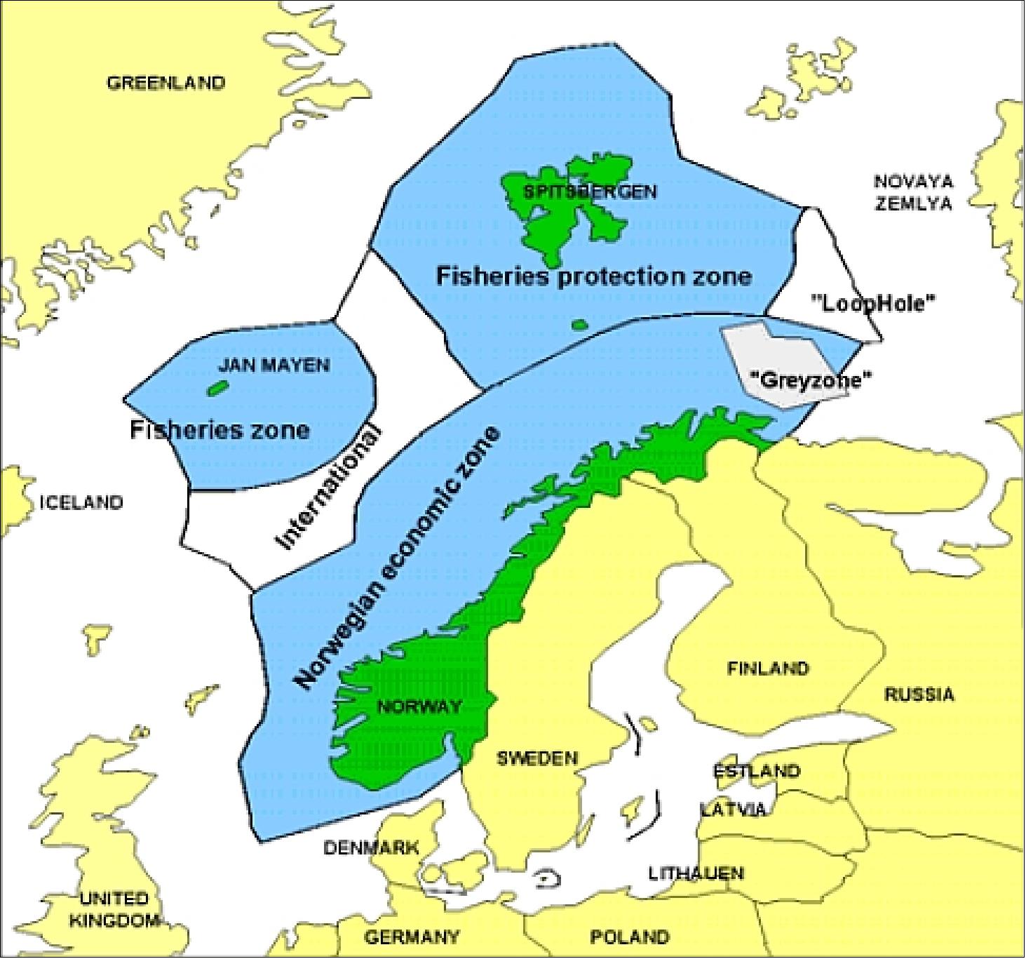
As of 2008, Norway, a nation of long shorelines, large coastal waters and fishing grounds, is in the process to build its first dedicated satellite (AISSat-1) for such spaceborne monitoring services of AIS signals. The justification for the mission is based on careful modeling of the global AIS detection probability, with particular emphasis on observation of Norwegian ocean areas in the High North.
AISSat-1 is a Norwegian nanosatellite technology demonstration mission in LEO, funded by the NSC (Norwegian Space Center, O) with program management by the FFI (Norwegian Defense Research Establishment). The overall objective is to investigate and assess the feasibility of a much needed national maritime situational awareness service. 4) 5) 6) 7) 8)
Collaboration: The Norwegian Space Center is project owner. The Norwegian Coastal Administration will receive the data and FFI is responsible for the technical implementation.
FFI has examined both technical and organizational aspects of monitoring AIS signals from space, to evaluate the possibility of extending the coverage area of AIS to all ocean areas under Norwegian jurisdiction. A comprehensive observation model for estimating the AIS signal environment in LEO (Low Earth Orbit) has been developed, making it possible to evaluate various concepts for AIS satellite missions to meet Norwegian and also more global requirements.
Spacecraft
AISSat-1 has been constructed on behalf of the government of Norway by UTIAS/SFL (University of Toronto, Institute for Aerospace Studies/Space Flight Laboratory), Toronto, Canada. The AIS sensor is a software defined radio system developed by Kongsberg Seatex AS (KSX) of Trondheim, Norway.
The satellite design is based on the modular GNB (Generic Nanosatellite Bus) of UTIAS/SFL first introduced in the CanX-6 / NTS mission (launch April 28, 2008). The GNB was originally developed for the BRITE (BRIght-star Target Explorer) constellation of Austria and for the CanX-4/-5 missions (all under development as of 2008), and is now also being leveraged for other missions as well.
The GNB platform is a cube of 20 cm side length, using an Al 6061-T6 structure, featuring two internal trays and six external panels. A dual tray structure was selected to maximize the payload bay and to provide ease of integration. The two trays contain all the necessary components for a basic satellite mission, including communications, attitude determination and control, power and thermal/structural components (Figure 6). A full suite of advanced capabilities is included: 9) 10) 11) 12)
• A dual battery, gallium arsenide triple-junction solar cell based power system that includes peak power tracking capabilities
• A full 3-axis attitude determination and control system that allows arbitrary inertial or orbit-frame alignment (including nadir, along-track and cross-track)
• A powerful complement of on-board computer processing systems, this includes a computer dedicated to payload activities
• A flexible TT&C and payload data communication system, allowing for variable and high speed data downlinks to the ground
• A large accommodation for payloads, including volume, pass, power, and spacecraft surface area.
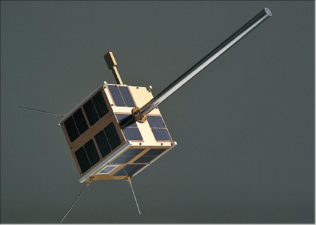
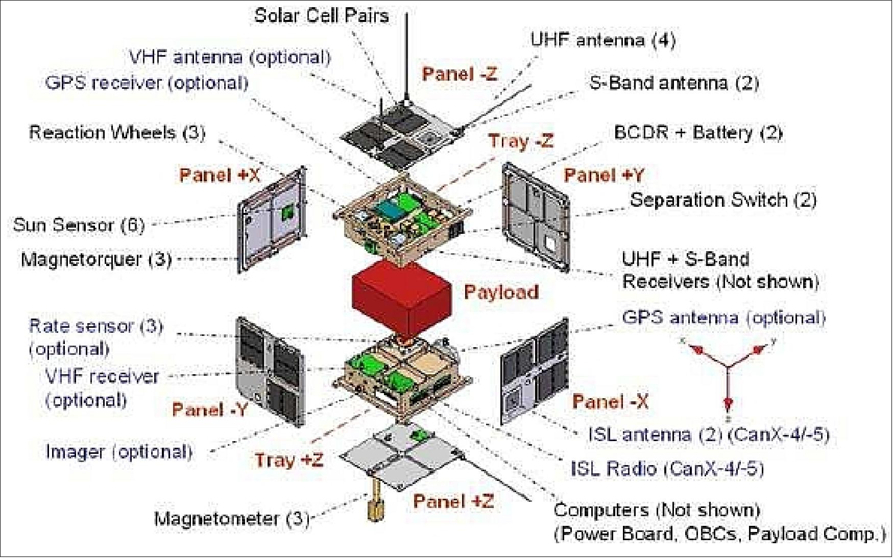
Two views of the AISSat-1 system, pointing out some external components, are provided in Figures 4 and 5.
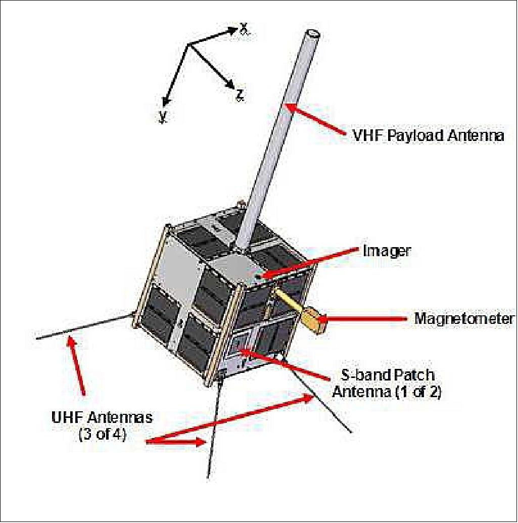
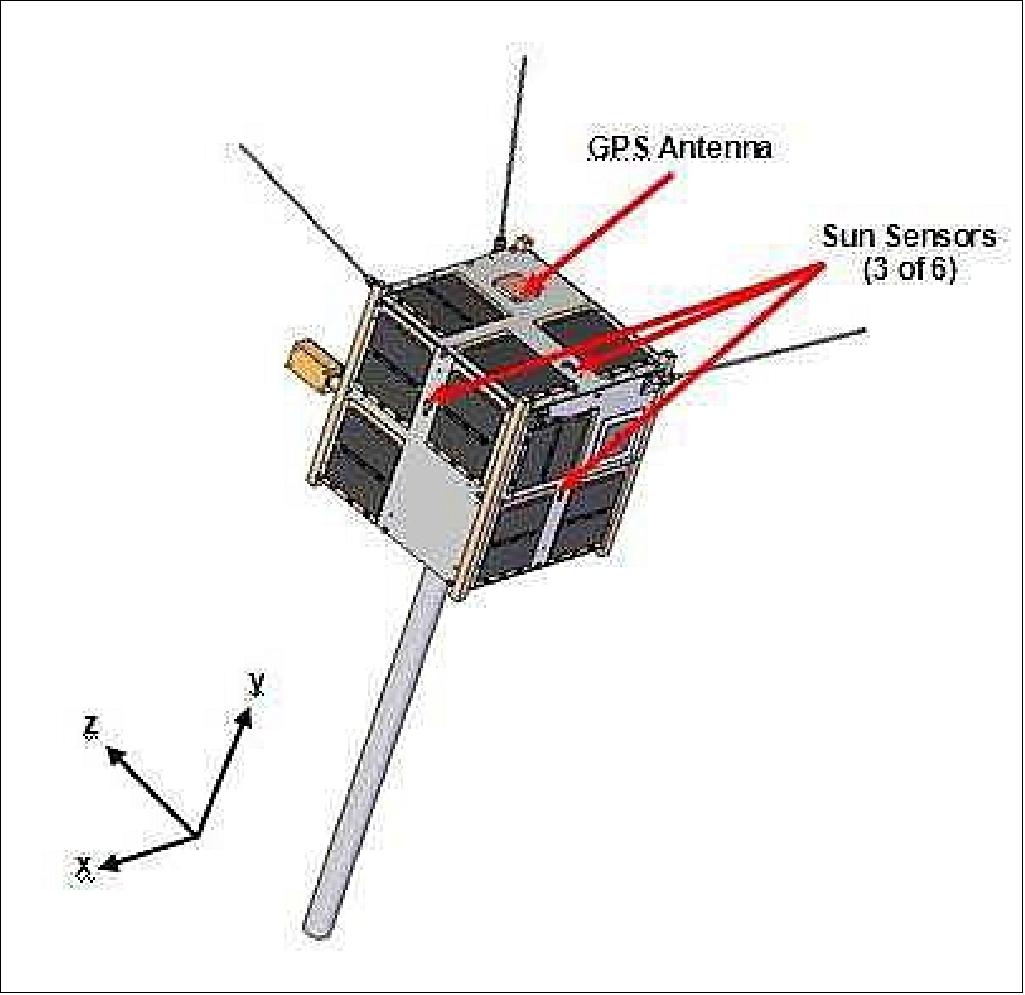
AISSat-1 also includes a custom designed VHF monopole payload antenna, as shown in Figure 4. The antenna is pre-deployed and designed to survive launch conditions in any orientation. It is also designed to be easily removed from the spacecraft without removing any of the spacecraft panels, allowing for easier testing, handling, and safety during shipment.
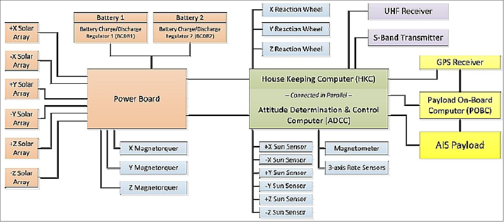
OBCs (On Board Computers): The spacecraft is equipped with three OBCs. Each OBC features an ARM7 microcontroller, 2 MB of EDAC protected SRAM and 256 MB of flash memory. The housekeeping computer is responsible for communications with the ground station and collecting satellite telemetry. The ADCC (Attitude Determination and Control Computer) interfaces with the attitude sensors and actuators and runs the attitude control algorithms.
On AISSat-1, a mission specific payload OBC is responsible for interfacing with and collecting data from the AIS sensor and GPS receiver (the main rational for the GPS receiver is to provide an accurate clock for the AIS receiver). The computer allows different data collection, storage, and processing modes, and permits in-flight updates to the AIS sensor. Each OBC runs a custom made multi-threaded operating system called CANOE (Canadian Advanced Nanospace Operating Environment) allowing it to divide processing time between multiple tasks in parallel.
EPS (Electric Power Subsystem): Spacecraft power is generated with 36 body-mounted triple junction GaInP2/GaAs/Ge solar cells. These cells have a BOL efficiency of 26.8%, delivering up to 967 mW at their peak power point at 28ºC. The energy is stored in a dual-5.3Ah lithium-ion battery system allowing the satellite to operate in extended eclipse periods and to reduce depth of discharge on the individual batteries. The power system architecture contains peak power tracking functionality and provides switched power to the loads and power regulation where required. Finally, over-current protection is provided to prevent damage to the payloads.
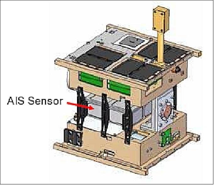
AISSat-1 employs mostly passive thermal controls in the form of coatings and structures. As the battery possesses the most stringent thermal requirements, it requires thermal isolation and a trim heater to meet a large variety of orbital scenarios.
ADCS (Attitude Determination and Control Subsystem): The nanosatellite features a full 3-axis ADCS with a fine pointing capability. The satellite is able to point in either an inertial orientation, or in an orbit-frame-fixed orientation, including nadir pointing. The attitude sensors consist of six sun sensors, a magnetometer and three rate gyros.
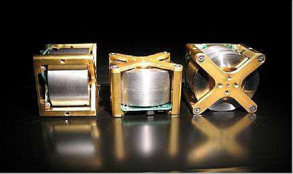
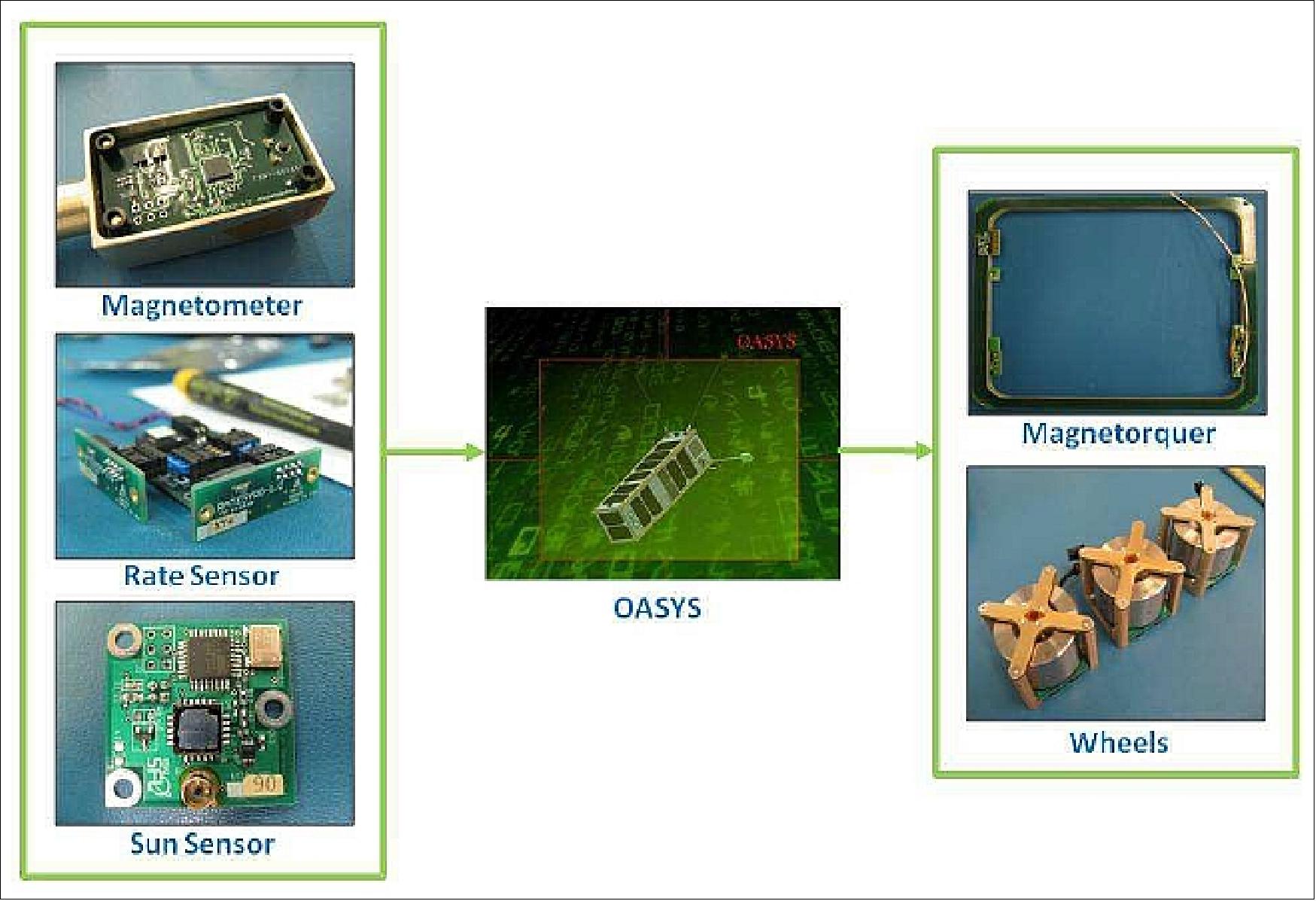
Actuation is provided by three orthogonally mounted reaction wheels (Figure 7) which were developed by SFL in partnership with Sinclair Interplanetary of Toronto, and three magnetorquer coils. The coils are used for detumbling and momentum dumping while the reaction wheels provide fine attitude pointing capability. The attitude control system is able to maintain a several degree level pointing accuracy and stability over the course of the entire orbit, including eclipse.
Each reaction wheel fits within a box of 5 cm x 5 cm x 4 cm, has a mass of 185 g, and consumes only 100 mW of power at nominal speed. A max torque of 2 mNm is provided (30 mNms momentum capacity).
The multi-mission-design architecture for the GNB attitude subassembly is shown in Figure 8, where the OASYS (On-Orbit Attitude Subsystem Software), which is comprised of an EKF (Extended Kalman Filter ), and a set of control laws, is constant for every mission. All control laws fly for all missions, however, which ones are actually available and used depends on the particular mission needs and hardware complement. Which sensors and actuators are incorporated depends on the mission. Specific components can be added or subtracted with minimal interfacing effort, giving both the software and hardware significant modularity. 13)
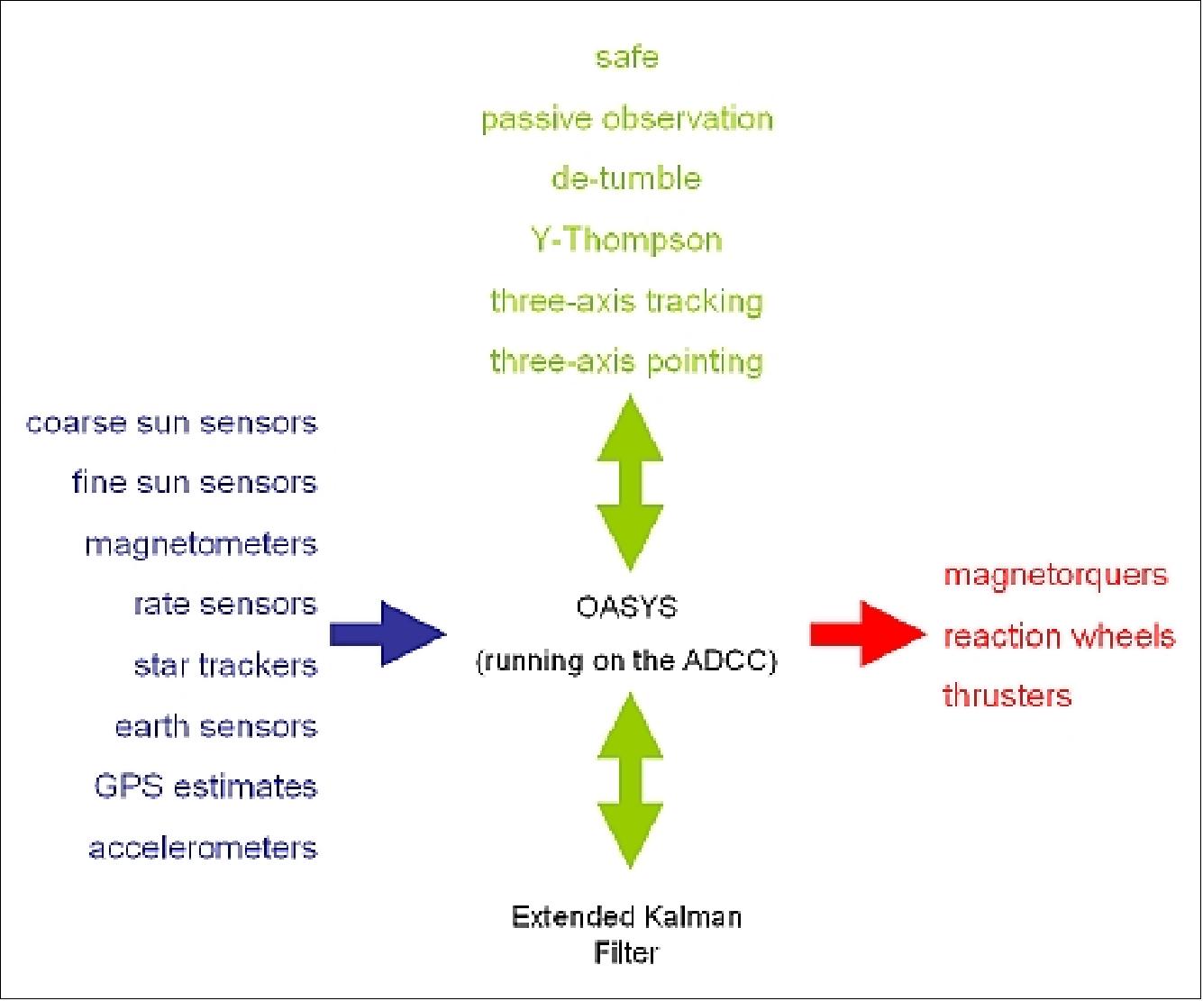
OASYS is the flight software that performs all the necessary computations for attitude determination and implements attitude-control laws to achieve a desired attitude state (attitude quaternion, and angular velocity in the body frame of reference). It is in part comprised of a satellite-position propagator, a solar ephemeris and an IGRF-11 (International Geomagnetic Reference Field-11th generation), magnetic-field, model of the Earth. These models are used in conjunction with sensors to estimate the satellite’s attitude by means of an EKF. The control laws are then implemented based on the estimated state. The attitude software is run at a fixed-but-configurable frequency of 0.5 Hz on a dedicated ADCC (Attitude Determination and Control Computer ). Each 2 s frame has a series of events, the order of which does not change: read sensors, run OASYS and command the actuators.
A host of control laws have been designed within OASYS to enable a very wide range of missions, however a fundamental suite of three are predominantly used. This includes the B-dot magnetic controller that requires only knowledge of the rate of change of the local magnetic field in the body frame, to null body-rates. Second, in order to prevent the saturation of the reaction wheels, through the action of secular disturbance torques, a magnetic momentum management controller, of the form of a simple proportional controller acting on the error relative to a reference momentum is used. Third, in order to actually point the GNB, a three-axis controller in the form of a linear quaternion and linear bodyrate feedback PID controller is used. This near-minimum-time eigen-axis rotation controller is capable of holding to an inertially-fixed target, or given a set of roll, pitch and yaw angles, tracking a fixed target relative to the moving classical orbit frame (Ref. 13).
AISSat-1 was designed with a full complement of GNB hardware and software in addition to its payload elements, with the exception of a star tracker which was not required. Therefore, the attitude system hardware was comprised of six digital sun sensors, one boom-mounted three-axis magnetometer, and one three-axis rate sensor to round out the determination suite. For control AISSat-1 employs three miniature reaction wheels and three vacuum-core magnetorquer coils.
The AISSat-1 nanosatellite has a mass of ~6.5 kg.
Launch
AISSat-1 Launch
AISSat-1 was launched as a secondary payload on July 12, 2010 on a PSLV launcher of ISRO (PSLV-C-15) from the SDSC-SHAR (Satish Dhawan Space Center) at Sriharikota. 14) 15)
The primary spacecraft on this flight was CartoSat-2B of India (694 kg), funded by the Ministry of Defense of the Government of India. 16)
Further secondary payloads on this flight are:
• AlSat-2A (Algeria Satellite-2) of CNTS (Algerian National Space Technology Centre) built at EADS Astrium SAS, France (116 kg).
• TISat-1 (Ticino Satellite-1), a CubeSat (1 kg) of SUPSI (Scuola Universitaria Professionale della Svizzera Italiana — University of Applied Sciences of Southern Switzerland), Lugano-Manno, Switzerland.
The AISSat-1 and TISat-1 spacecraft were launched and deployed with XPOD (Experimental Push Out Deployer) of UTIAS/SFL. UTIAS/SFL refers to this service as NLS-6 (Nanosatellite Launch Service-6). 17) 18) 19)
• StudSat (Student Satellite), a picosatellite (1 kg) built by a consortium of seven Engineering colleges from Hyderabad and Bangalore, India.

Orbit: Sun-synchronous polar orbit, altitude of 635 km, inclination= 97.71º, equator crossing at 9:30 hours LTDN (Local Time on Descending Node), period = 97.4 minutes.
RF communications: The AISSat-1 platform contains two radio systems: a UHF-band receiver, and an S-band transmitter. The UHF-band receiver, operating at 4 kbit/s, is used for data uplink from the ground station and uses four phased quad-canted monopole antennas which provide near omnidirectional coverage. The S-band transmitter will be used for the data downlink. It is capable of data rates in the range of 32 to 256 kbit/s; it uses two patch antennas mounted on opposite sides of the satellite for near omnidirectional coverage.
According to the contract agreement, UTIAS/SFL is providing the spacecraft platform and the AIS VHF antenna, and providing spacecraft-level management, systems engineering, assembly, integration, and test support. UTIAS/SFL will also be responsible for launch and the commissioning phase, after which the spacecraft will be delivered to FFI for operations.
AISSat Constellation
Following the success of AISSat-1, the Norwegian authorities decided that the AIS-from-space capability had proven to be extremely valuable and the usage of its data in the operational AIS network was of long-term strategic interest. In order to maintain the capability, a second satellite, AISSat-2, was ordered in early 2011. AISSat-2 is a build-to-print copy of AISSat-1.
The second satellite in this constellation series, AISSat-2, has been completed and was launched on July 8, 2014 on a Soyuz launcher from the Baikonur Cosmodrome in Kazakhstan. Two AIS satellites in orbit will ensure a continuous monitoring and safeguarding of the maritime traffic in Norwegian waters. 20)
The third satellite, AISSat-3, is under construction at UTIAS/SFL and will be launched in 2016. 21)

The primary purpose of AISSat-2 and AISSat-3 is to provide a higher level of capability assurance. Specifically, it is to be considered an in-orbit backup to AISSat-1 to avoid a loss of AIS-from-space capability should there be an on-board failure that results in a loss of AIS data capture capability. In this sense, the two satellites will be backups for each other and provide the overall system with a full single fault tolerance capability. Through this redundancy, Norway’s AIS-from-space capability has a higher degree of assurance of continuity.
AISSat-2 Launch
The AISSat-2 nanosatellite was launched as a secondary payload on July 8, 2014 on a Soyuz-2.1b/Fregat launch vehicle from the Baikonur Cosmodrome, Kazakhstan. The primary payload on this flight was Meteor-M2 spacecraft. The launch provider was NPO Lavochkin. 22) 23) 24)
The planned mid-December 2013 launch has been delayed again following the latest series of issues with the primary satellite payload. Russia’s Meteor-M2 polar-orbiting meteorological satellite has faced delays in the past that have kept the secondary payloads — Norway’s AISSat-2, Canada’s M3MSat, Britain’s TechDemoSat-1 and UKube-1 among them — on the ground. 25)
The Soyuz delay follows a two-year grounding of the Russian-Ukrainian Dnepr silo-launched rocket, which small-satellite owners hope may now be returning to the market pending an agreement between Russia’s military space forces and the Russian space agency, Roskosmos.
Some background: At various points in time, the secondary payloads during the launch of Meteor-M2 also included the Baumanets-2 experimental satellite for the Bauman State Technical University in Moscow, the M3MSat for the Canadian Space Agency and Venta-1 (Ventspils University, Latvia). Baumanets-2 and Venta-1 were dropped from the mission at the early planning stage.
Secondary Payloads
• MKA-PN2 (Relek), a microsatellite of Roskosmos, S/C developer NPO Lavochkin on the Karat platform (59 kg, study of energetic particles in the near-Earth space environment (ionosphere) including the Van Allen Belts.
• DX-1 (Dauria Experimental-1), the first privately-built and funded Russian microsatellite (22 kg) of Dauria Aerospace, equipped with an AIS (Automatic Identification System) receiver to monitor the ship traffic. 28)
• TechDemoSat-1 of UKSA/SSTL, UK with a mass of 157 kg.
• SkySat-2 of Skybox Imaging Inc. of Mountain View, CA, USA, a commercial remote sensing microsatellite of ~100 kg.
• M3MSat dummy payload of 80 kg.
• AISSat-2, a nanosatellite with a mass of ~7 kg of FFI (Norwegian Defense Research Establishment) Norway, built by UTIAS/SFL, Toronto, Canada.
• UKube-1, a nanosatellite (~3.5 kg) of UKSA/Clyde Space Ltd., UK.
Orbit: Sun-synchronous circular orbit of Meteor-M2, altitude of ~ 825 km, inclination = 98.8º, period = 101.41 minutes, LTAN (Local Time on Ascending Node) at ?? hours.
Orbit of the secondary payloads: Sun-synchronous near-circular orbit, altitude of ~ 635 km, inclination = 98.8º. The MKS-PN2 (Relek) was released first of the secondary payloads into an elliptical orbit of 632 km x 824 km.
Mission Status
• July 10, 2020: Kongsberg is celebrating 10 successful years since the AISSat-1 AIS-receiving satellite, complete with its Kongsberg AIS payload, was launched from the Satish Dhawan Space Centre in India on July 12, 2010. 29)
- The game-changing AISSat-1, the first operational AIS receiver in space, is financed by the Norwegian Ministry of Trade and Industry and deploys technology which was developed collaboratively by Kongsberg Seatex with the Norwegian Space Centre, the Norwegian Defence Research Establishment and the Norwegian Coastal Administration.
- Launched via an Indian PSLV rocket, the 20 x 20 x 20 cm, 6 kg, cube-shaped AISSat-1 smallsat has been maintaining an SSO polar orbit at an altitude of approximately 635 km for a full decade now, receiving AIS messages from ships all over the globe and transmitting them to Earth via Kongsberg Satellite Services’ Svalbard-based ground station.
- While the 10th anniversary of the AISSat-1 launch is justifiable cause for celebration, Kongsberg is nevertheless firmly focused on the future. Kongsberg’s status as a driver of constantly evolving technologies has positioned the company as a key player in the development of the next-generation VDES (VHF Data Exchange System) payload. Visualized as an extension to AIS, this robust, narrow-band, high-speed, two-way VHF ship communications system will establish a global standard designed to support the transformative digitalization of the maritime community. Accordingly, next-generation AIS equipment for commercial shipping will incorporate both AIS and VDES in the same unit.
- Arve Dimmen, Director of Maritime Safety at the Norwegian Coastal Administration, still marvels at the radical difference the AISSat-1 made to the supervision of shipping in the high north once it entered service.“It was almost like ‘turning on the light,’ he recalls, “as the satellite enabled us to get a much better overview of the marine traffic in our sea areas. The satellite data is distributed to several public authorities: Joint Rescue Coordination Centers, the Coast Guard and the Norwegian Directorate of Fisheries are among some of the most frequent users. The data can be used to monitor fishing activities and to monitor search and rescue operations at sea. AISSat-1 was the starting point of our satellite program for maritime surveillance, and it has been a great success.”
- “The 10th anniversary of successful AISSat-1 service, together with a wide range of additional, successful missions in the past decade, have definitely demonstrated that we have taken a lead in innovative space payload solutions for maritime applications,” added Gard Ueland, President, Kongsberg Seatex. “These missions show that, with a NewSpace approach, it is possible to establish highly successful and cost-efficient space infrastructures using micro- and nanosatellites. VDES represents a bold step forward in the efficient monitoring and management of vessel traffic, leading to greatly enhanced safety on board and in ports. With the ongoing overhaul of the AIS infrastructure both at sea and on land, we can expect to see a substantial uptake of VDES services over the next years.”

• October 2018: Since the launch of AISSat-1 in 2010, significant improvements have been made in the Norwegian maritime satellite fleet. In 2014, AISSat-2 was launched, enhancing not only overall revisit frequency, but also the quality and reliability of the data thanks to an upgraded AIS receiver. Both satellites are based on the GNB (Generic Nanosatellite Bus) of UTIAS/SFL. They have dimensions of 20 x 20 x 20 cm and a mass of 6.5 kg. Both are still operational, well beyond their design life of three years. 30)
- A third and similar satellite, AISSat-3 was developed to replace AISSat-1 and complete the constellation. It contained a new generation AIS receiver (ASR 300) as well as upgraded on-board computer software and an improved S-band transmitter capable of faster downlink rates. Unfortunately, AISSat-3 never reached orbit due to a launch failure in November 2017 (the Soyuz-2.1b/Fregat-M from the Vostochny launch site experined a launch failure).
- AISSat-1 and -2 not only gave Norwegian governmental users invaluable data and improved greatly the maritime picture in remote areas, they also provided industrial growth in a new Norwegian segment and demonstrated to Norwegian authorities and politicians that small satellites were a sensible and cost-efficient means for Norway to use new technology to the benefit of a variety of user groups. However, it was clear that the resources available (mass, volume, power and data budget) on the AISSat platforms were inadequate for a significant development of the AIS payload and potentially auxiliary payloads. Therefore a contract for a satellite bus with increased capacity and capability was competed with SFL selected as the provider.
• March 2, 2016: AISSat-1 and AISSat-2 are still operational. As of May 2015, the operations of the satellites were transferred from FFI (Norwegian Defense Research Establishment) to Statsat AS, a subsidiary of Space Norway AS and a 100% governmentally owned company that defines, develops and sources space infrastructure for Norwegian public purposes.
- AISSat-1 has now more than 5.5 years of operation on it’s back. This is over 4 years more than it’s design life. The project is very happy with its performance. Currently, one of the batteries is showing signs of wear, but nothing that seems to limit performance. AISSat-2 is running perfectly after 1,5 years in flight. 31)
• 2014: The AISSat-1 spacecraft and its payload are fully operational. The mission continues to provide a very valuable service to the Norwegian Coastal Administration. The mission goal for the satellite was originally 3 years, which it successfully completed in July 2013. With no degradations or problems onboard, the mission might probably provide its service for another three years. 32)
- During 2013, AISSat-1 received several software upgrades resulting in improved performance. The main upgrade consisted of new firmware for the SDR that included improved AIS decoding algorithms. The update was based on experience from testing of similar updates on the NORAIS Receiver which has been running on the ISS (International Space Station) since June 1st 2010. Since the upload of the new code at the end of May 2013, AISSat-1 has had a roughly 20% increase in performance at the cost of an increased payload power consumption of only 10%. 33)
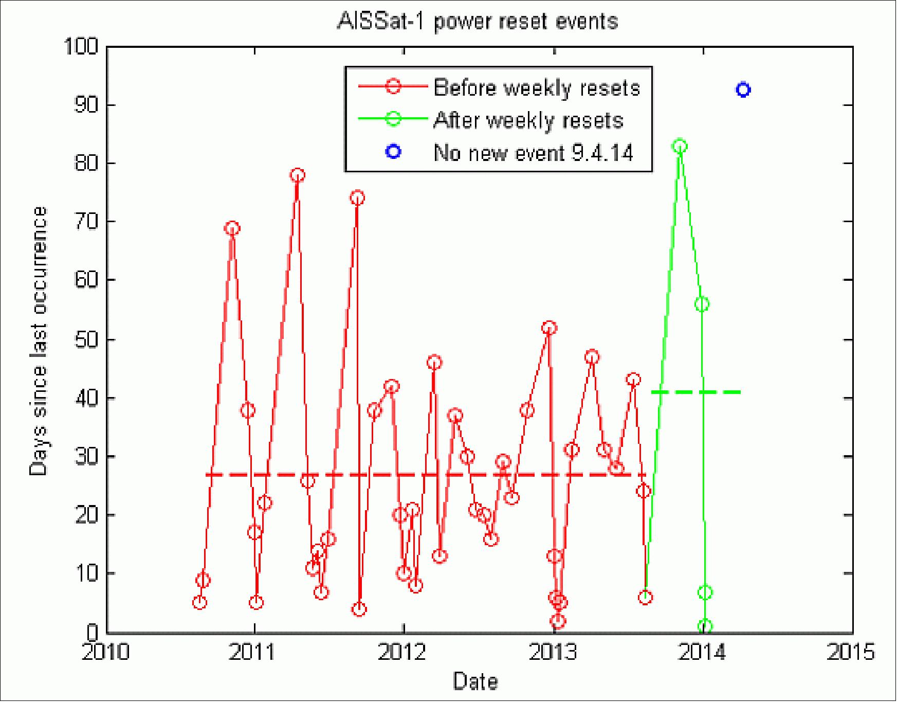
- The AISSat-1 satellite platform suffers from random power resets with a Mean Time Between Failures (MTBF) of 25 days. It is possible to mitigate the rate of these resets by occasionally performing manual power board resets. This has been done on a weekly basis since 23 August 2013 and has increased the MTBF and reduced system downtime. In addition, since the probability of a reset increases with time, performing the manual power resets close to the weekend will further decreased the system downtime. Figure 14 shows the date of random power resets and the number of days since last occurrence. The events prior to, including manual power resets in the weekly operations, are shown in red and the events after in green. The MTBF of each period is plotted as a dashed line, the MTBF after the weekly manual resets takes into account that there has been no random power resets since January 7, 2014 when this data was plotted (April 9, 2014).
- In mid-2013 the MCC (Mission Control Center), the Ground Station (GS) and the satellite all received software upgrades. The project has experienced some instabilities with the new versions, in particular the program that downloads the AIS data from the satellite. The program “freezes” and is unable to download any data until it is restarted. Unlike a power reset, this does not result in a loss of AIS data, but a delay in the data delivery is encountered as the files generated are stored in the satellite. This is also the most common effect of other GS and MCC software crashes.
- The number of vessels per day leading up to the upgrade in 2013 shows consistently higher values than in 2012. This cannot directly be interpreted into a growth in the global vessel traffic. AISSat-1 has limited detection probability in areas with high vessel densities like the Gulf of Mexico, European waters with the exception of the High North and the waters off the coast of South East Asia. In areas with low vessel densities we expect to detect effectively every vessel with the AIS transponder on after a day. To convert the number of vessels into a global traffic model, it is necessary to estimate the satellite’s regional detection probabilities. The results from such an analysis indicate that the global growth has been around 5% per year since the launch of the satellite.
- Figures 15 and 16 show the total number of received messages and the total number of distinct vessels seen per day. The figures show that the update improved the number of received messages by roughly 20% and the number of unique vessels by roughly 15%.
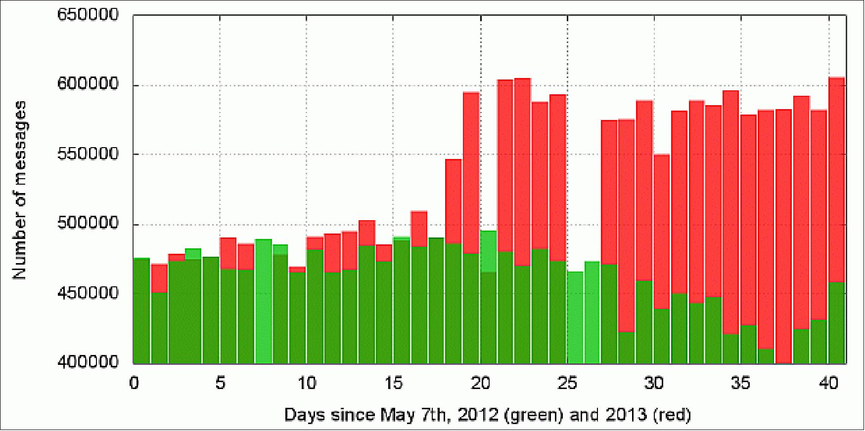
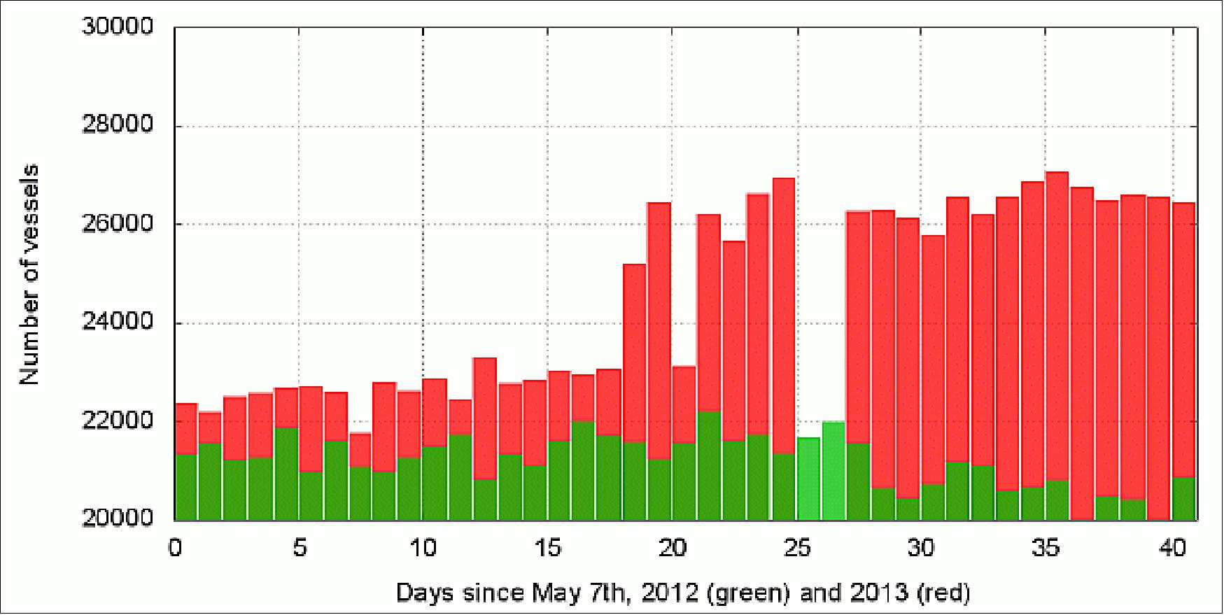
- Some more detailed studies were done along the coast of Norway where access to coastal AIS was used as a kind of ground truth. Two time periods from 2013 were compared. May 7-13, 2013, representing the old algorithm and May 25-30, 2013, representing the new improved algorithm. For each of the time periods the following comparison with coastal data was done (Ref. 33):
1) For each orbit in the period coastal data was stored for a time period corresponding to AISSat-1s coverage over the Svalbard ground station.
2) For each degree of latitude from 62ºN to 70ºN and for two regions north of 70 º, all vessels found in the coastal data were identified.
3) For each of the vessels found within a latitude region a search was done to see how many of the vessels had been detected by AISSat-1 within ±1 hour and within ±6 hours.
• The AISSat-1 spacecraft and its payload are operating nominally in the summer of 2013 (3 years on orbit). Since the launch of AISSat-1 in July 2010, AIS has gone from being an experimental service to being a fully operational capability that authorities responsible for maritime safety and security worldwide have become more or less reliant on. 34) 35)
To maintain the satellite AIS service to Norwegian authorities, a copy of AISSat-1, namely AISSat-2, has been built to serve as an in-orbit spare for AISSat-1, as well as to provide more vessel traffic data (AISSat-2 will be launched in Q2 2014). Both satellites will operate simultaneously, but since neither satellite has on-board propulsion, the orbits will drift independently from each other (Ref. 34).
• In July 2012, the AISSat-1 nanosatellite marks two years on orbit. In general, the payload operations of AISSat-1 during the first two years of operations can be divided into three periods as shown in Figure 17. The first AIS messages from AISSat-1 were forwarded to the NCA (Norwegian Coastal Administration) already in the afternoon after the launch. From early on, live AIS data were gathered. UTIAS/SFL had in the first month’s responsibility for the commissioning of the satellite, but unless the satellite needed to operate in a special mode due to the commissioning, live AIS data were provided when the satellite was in contact with Svalbard. 36)

- AISSat-1 is a very successful operational mission, and has shown that a nanosatellite on a small budget can provide a service that is able to meet many users’ operational requirements globally. AISSat-1 has already provided an exceptional data set for both research and operational use; the project is confident to continue this service for the foreseeable future.
- Except for one weekly interaction for uploading new time tagged commands, new orbit element information and adjust the onboard clocks, the operations of AISSat-1 after 2 years are mainly hands-off. Both the satellite and the on-ground software and hardware are working excellently, enabling FFI to focus more on research than on operations (Ref. 36).
• The attitude subsystem of the SFL’s GNB (Generic Nanosatellite Bus) can support a wide range of missions, as well as a range of platforms, as the GNB ADCS was recently extrapolated for use for SFL’s third generation nanosatellite bus, the NEMO-class bus, which is a 15 kg nanosatellite, and COM DEV’s AIM-class 70 kg microsatellite bus. The GNB ADCS is now flight proven with currently nearly 2 years experience on the AISSat-1 mission, and significant aspects of the attitude system have over four years of flight heritage on SFL’s CanX-2 technology demonstration mission (Ref. 13).
The same reference also outlines the details of the ADCS commissioning phase (prior to Nov. 26, 2010) regarding:
- ADCS hardware checkout
- Attitude solution verification of OASYS
- ADCS control algorithm performance.
• The AISSat-1 spacecraft and its payload are operating nominally in 2012. 37)
• In August 2011, AISSat-1 has operated for more than a year and has provided a new and valuable maritime observation tool to Norwegian authorities for improved maritime situational awareness of Norwegian and international waters. The up-time for AISSat-1 has been better than 95% (Ref. 7).
• In January 2011, FFI ordered AISSAT-2 (a copy of AISSAT-1) from UTIAS/SFL. In 2013, the two satellites will form the first Norwegian observational asset in space with an increased coverage capability. 38)
• In March 2011, AISSAT-1 data was offered to the Japanese Coast Guard by the Norwegian Coastal Administration. After the earthquake and the follow-up catastrophic Tsunami on March 11, 2011, the AISSat-1 steering committee decided to reprogram the satellite so it could be of use in vicinity of the areas where the disaster struck. The steering committee consists of members from the Norwegian Coastal Administration, the Norwegian Defence Research Establishment and the Norwegian Space Centre, which is the owner of the satellite.
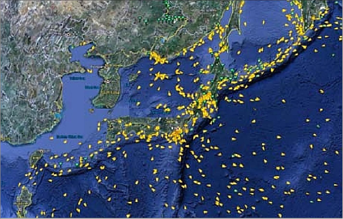
• On January 12, 2011, the AISSAT-1 mission celebrated six months of successful operations in orbit. AISSat-1 was launched on 12 July 2010. 39)
• On Nov. 26, 2010, AISSat-1 GNB commissioning was formally “handed over” by SFL to the Norwegian Defence Research Establishment (FFI) . The Norwegian authorities took over full operational responsibility for the mission using its ground station at Svalbard. However, SFL continues to provide technical support as needed for the mission. - AISSat-1 was recently voted Norway’s top technological achievement for 2010.
With the successful implementation of the AISSat-1 mission, the GNB platform has been verified and the broader utility of capable nanosatellite platforms in solving operationally-relevant real-world problems has been demonstrated. The AISSat-1 mission has demonstrated that a high degree of operational reliability can be obtained in a low-cost, high-performance nanosatellite platform (Ref. 13).
• In the months following launch, all the systems of the satellite were successfully commissioned, including its three-axis attitude control system that enables inertial pointing to within 1-2º. The full pointing control demonstrated by AISSat-1 is likely the first time that such pointing performance has been demonstrated on a nanosatellite.
• Owing to the excellent early operations results, the AISSat-1 payload was activated in its real-time mode for the first time less than 12 hours after initial acquisition and the system was able to receive and disseminate live AIS message traffic from the High North immediately. Thus in a very short time, the mission was able to complete a number of critical mission milestones and demonstrate high confidence in the larger mission.
- Within one day after launch, the satellite was detecting ships over Norwegian waters and a press release was issued with data from space. The satellite was collecting AIS (Automatic Identification System) data very soon after launch and before all its systems had been fully commissioned - and transmitted the AIS messages to a KSAT (Kongsberg Satellite Services) ground station in Svalbard. 40) 41)
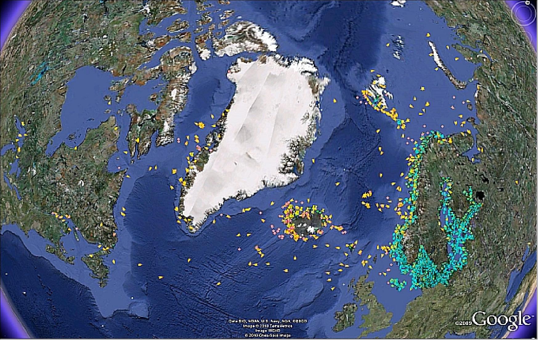
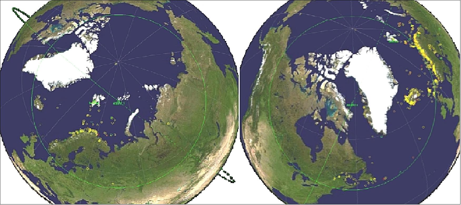
Legend to Figure 19: The yellow and orange symbols shows the new AIS-data that comes in addition to data from coastal AIS infrastructure.
Sensor Complement
AIS (Automatic Identification System)
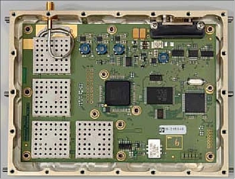
The AIS receiver,named ASR 100, designed and developed at KSX (Kongsberg Seatex AS, Trondheim, Norway), is a self-organizing TDMA (Time Division Multiple Access) radio-communication system used for the identification and location of maritime vessels - the implementation is referred to as SDR (Software Defined Radio). The AIS signals are sampled and forwarded to the FPGA (Field Programmable Gate Array) for further processing. Using a reprogrammable FPGA enables in-flight finetuning of the AIS sensor based on analysis of received AIS data; it also allows the FPGA to be completely reprogrammed to take advantage of major future design and functionality improvements. 42)
The microcontroller communicates with the satellite platform by sending and receiving data packets on a serial RS-485 line. The controller also holds the radio setup information in addition to FPGA configuration images.
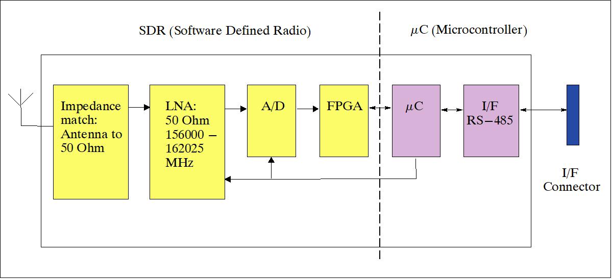
The AIS sensor for this mission is basically a dual-channel VHF receiver, which can be tuned to any of the VHF channels in the maritime VHF band ranging from 156,025 to 162,025 MHz. When listening for AIS messages broadcasted on the two designated AIS channels, the radio will be tuned to VHF channels 87B and 88B (161.975 and 162.025 MHz respectively).
Note: NORAIS (Norwegian Automatic Identification System), practically a duplicate of AIS on AISSat-1, and built by the same team, was brought to the ISS (International Space Station) by the Japanese HTV (H-2 Transfer Vehicle) on its maiden flight (launch Sept. 11, 2009). NORAIS is bound for Columbus, the European space laboratory on the International Space Station. This winter, a specially constructed antenna will be brought to the ISS and fitted on the outside of Columbus. From then on, the testing of NORAIS started. 43)
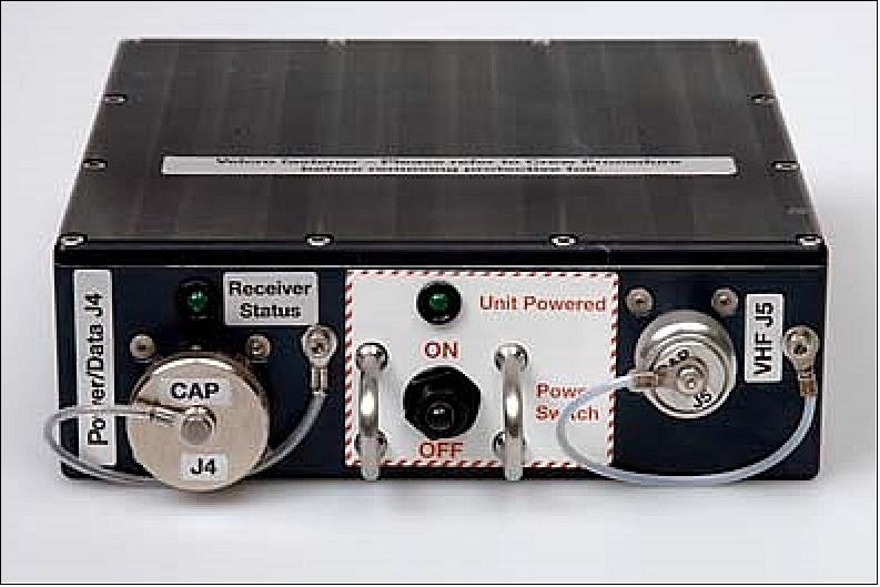
The installation of NORAIS on the Columbus module has enabled FFI, together with KSX, to do research and testing of new and upgraded algorithms on the ISS, enabling AISSat-1 to be fully focused on being an operational data provider. A final upgrade of the NORAIS receiver was developed by KSX in spring 2013 and this showed such good results that the Norwegian Coastal Administration procured a similar upgrade for the AISSat-1 payload. Since the upload of the new firmware image to the satellite at the end of May 2013, AISSat-1 has had a roughly 20% increase in performance at the cost of an increased payload power consumption of only 10% (Ref. 33).
Ground Segment
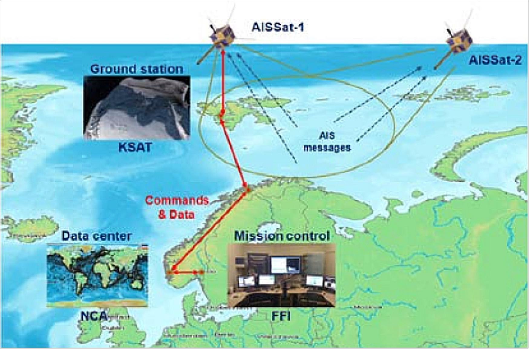
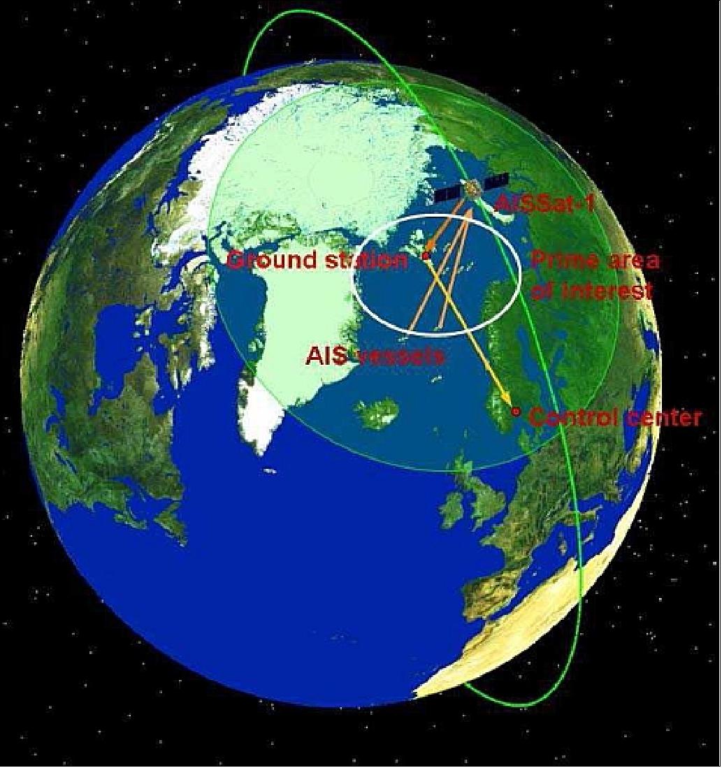
The ground station is located in Svalbard to acquire data from AISSat-1 during all 15 daily passes over Norwegian ocean areas. KSAT (Kongsberg Satellite Services) already has a major facility for communicating with numerous satellites. The Svalbard Ground Station (also referred to as SvalSat), is located at 78.216º N, 20º E on the Norwegian Svalbard archipelago (also referred to as Spitzbergen) near the town of Longyearbyen.
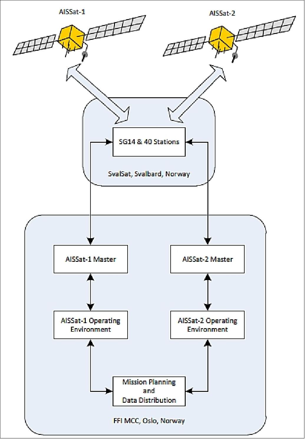
Stored and real-time data from the satellite is acquired and stored at the ground station for subsequent forwarding to the NCA (Norwegian Coastal Administration) in Haugesund and to the MCC (Mission Control Center) located at FFI, Kjeller, in southern Norway.
The satellites (AISSat-1 and -2) use two physical Earth stations for UHF and S-band frequencies. The S-band station, SG40, is shared with other missions such as PROBA-2. SG40 is scheduled by KSAT scheduling mechanisms outside of the framework’s control, and this information is used to schedule the other Earth station (SG14). The framework’s ability to handle external scheduling mechanisms is utilized here to coordinate operations of the two Earth stations. 44)
AISSAT-1 Operations at MCC (Ref. 36):
The MCC runs autonomously most of the time. Status e-mails are generated during each contact with AISSat-1, notifying the operators if anything is wrong. The satellite is run by time-tagged commands generated once a week. Any manned operations take place during normal working hours, and the operators are scientists at FFI. If everything runs nominally, the only manual operations happen once a week when the clock and TLE (Two Line Elements) onboard AISSat-1 are updated, and when new time tagged commands are generated and added to an upload queue.
AISSat-1 is designed to have two basic observation modes. When the satellite is in contact with the Svalbard ground station, AIS messages from vessels within the satellite’s field of view are forwarded to the NCA and MCC in real time (< 1sec latency). This mode basically makes a maritime situational picture available to Norwegian authorities in real time. The program forwarding AIS data from the MCC to the NCA also plots the AIS positions in Tracker to give a visual confirmation that everything is working properly. An example of how “live” data received during a single pass is shown in Figure 26.
References
1) http://www.imo.org/Safety/mainframe.asp?topic_id=754
2) “Technical characteristics for an automatic identification system using time division multiple access in the VHF maritime mobile band,” ITU-R M.1371-3, January 1, 2007
3) Øystein Helleren, Øystein Olsen, Per Christian Berntsen, Karsten Strauch, Nader Alagha, “Technology reference and proof-of-concept for a space-based automatic identification system for maritime security,” Proceedings of the IAA Symposium on Small Satellite Systems and Services (4S), Rhodes, Greece, May 26-30, 2008, ESA SP-660, August 2008
4) Bjorn T. Narheim, Oystein Olsen, Oystein Helleren, Richard Olsen, Alexander M Beattie, Robert E. Zee, “A Norwegian Satellite for Space-based Observations of AIS in the High North,” Proceedings of the 22nd Annual AIAA/USU Conference on Small Satellites, Logan, UT, USA, Aug. 11-14, 2008, SSC08-III-3
5) Torkild Eriksen, Gudrun Høye, Bjørn Narheim, Bente Jensløkken Meland, “Maritime traffic monitoring using a space-based AIS receiver,” Acta Astronautica, Vol. 58, Issue 10, May 2006, pp. 537-549
6) Baard Kringen, “AISSAT-1, Monitoring the Shipping Traffic from Space,” NordicSpace, Vol. 17, No 4, 2009, URL: http://www.nordicspace.net/PDF/NSA238.pdf
7) Bjorn T Narheim, Oystein Helleren, Oystein Olsen, Richard Olsen, Harald Rosshaug, Alexander M Beattie, Daniel D Kekez, Robert E. Zee, “AISSat-1 Early Results,” Proceedings of the 25th Annual AIAA/USU Conference on Small Satellites, Logan, UT, USA, Aug. 8-11, 2011, paper: SSC11-III-6
8) “Norway's Satellites,” Norsk Romsenter, URL: http://web.spacecentre.no
/eng/Norway-in-Space/Norway-s-Satellites
9) http://www.spacecentre.no/?module=Articles;action=Article.publicShow;ID=51389
10) https://web.archive.org/web/20140320172843/https://www.utias-sfl.net/nanosatellites/AISSat-1/
11) F. M. Pranajaya, Robert E. Zee, “Generic Nanosatellite Bus for Responsive Mission,” 5th Responsive Space Conference, April 23–26, 2007, AIAA-RS5 2007-5005, Los Angeles, CA, USA, URL: https://web.archive.org/web/20150607212939/http://www.responsivespace.com/Papers/RS5/SESSION%20PAPERS/SESSION%205/5005_PRANAJAYA/5005P.pdf
12) Grant Bonin, Doug Sinclair, Robert E. Zee, “Peak Power Tracking on a Nanosatellite Scale: The Design and Implementation of Digital Power Electronics on the SFL Generic Nanosatellite Bus,” Proceedings of the 23nd Annual AIAA/USU Conference on Small Satellites, Logan, UT, USA, Aug. 10-13, 2009, SSC09-XI-9
13) Karan Sarda, Alex Beattie, Daniel D. Kekez, Robert E. Zee, “In-flight Experience of the High-Performance Attitude Determination and Control System of the Generic Nanosatellite Bus,” Proceedings of the 4S (Small Satellites Systems and Services) Symposium, Portoroz, Slovenia, June 4-8, 2012
14) http://www.isro.org/pslv-c15/pdf/CARTOSAT-2B-brochure.pdf
15) Daniel D. Kekez, Robert E. Zee, Freddy M. Pranajaya, “Launches and On-Orbit Performance - An Update on Nanosatellite Missions at the UTIAS Space Flight Laboratory,” CalPoly Summer Workshop, Aug. 7, 2010, URL: http://mstl.atl.calpoly.edu/~workshop/archive/2010/Summer/05%20-%20Kekez%20-%20UTIAS%20SFL.pdf
16) “Launch of PSLV-C15 rescheduled,” April 29, 2010, URL: http://www.isro.org/pressrelease/scripts/pressreleasein.aspx?Apr29_2010
17) https://web.archive.org/web/20161219040448/http://www.utias-sfl.net/NLS-6/
18) Daniel D. Kekez, Robert E. Zee, Freddy M. Pranajaya, “SFL Nanosatellite Missions, Nanosatellite Launch Service,”Summer Workshop, Aug. 11, 2007, URL: https://web.archive.org/web/20091229171246/http://mstl.atl.calpoly.edu:80/~bklofas/Presentations/SummerWorkshop2007/Kekez_Daniel.pdf
19) Daniel D. Kekez, Robert E. Zee, Freddy M. Pranajaya, “Launches and On-Orbit Performance - An Update of Nanosatellite Missions at the UTIAS Space Flight Laboratory,” 2010 Summer Workshop, Aug. 7, 2010, Logan, UT, USA, URL: http://www.cubesat.org/images
/cubesat/presentations/SummerWorkshop2010/kekez-utias_sfl.pdf
20) Berit Ellingsen, ”Norway's second satellite launched,” Norsk Romsenter, July 10, 2014, URL: http://www.romsenter.no/eng/News2/News/Norway-s-second-satellite-launched
21) Alexander M. Beattie, Øystein Helleren, Robert E. Zee, “In-Flight Operations of a High-Availability Nanosatellite Constellation for Maritime Observation,” Proceedings of the 64th International Astronautical Congress (IAC 2013), Beijing, China, Sept. 23-27, 2013, paper: IAC-13-B4.3.1
22) “Soyuz rocket with seven satellites lifts off from Baikonur,” ITAR-TASS, July 8, 2014, URL: http://en.itar-tass.com/non-political/739563
23) Anatoly Zak, “Russia launches new weather watcher,” July 9, 2014, URL: http://www.russianspaceweb.com/meteor_m2.html
24) Patrick Blau, “Soyuz successfully Launches Meteor-M #2 & Six Secondary Payloads,” Spaceflight 101, July 8, 2014, URL: http://www.spaceflight101.com/soyuz-2-1b---meteor-m-2-launch-updates.html
25) Peter B. de Selding, “Latest Soyuz/Fregat Delay Underscores Issue for Small-satellite Owners,” Space News, Sept. 27, 2013, URL: http://www.spacenews.com/article/launch-report
/37416latest-soyuzfregat-delay-underscores-issue-for-small-satellite-owners
28) “Dauria Aerospace and Samsung will launch the first in Russia private artificial satellite of the Earth,” Oct. 15, 2013, URL: http://all-rss.com/item-1070741-dauria-aerospace-and-
samsung-will-launch-the-first-in-russia-private-artificial-satellite-of-the-earth/#.UwSE3s7ihqM
29) ”Ten Successful Years for Kongsberg’s AISSAT-1,” Satnews, 10 July 2020, URL: https://news.satnews.com/2020/07/10/ten-successful-years-for-kongsbergs-aissat-1/
30) Jon Harr, Tyler Jones, Bo N. Andersen, Torkild Eriksen, Andreas N. Skauen, Knut Svenes, Eirik V. Blindheim, Ivar Spydevold, Alex Beattie, Laura M. Bradbury, Brad Cotten, Daniel Kekez, Payam Mehradnia Robert E. Zee, Frode Storesund, ”Microsatellites for Maritime Surveillance - an update on the Norwegian Smallsat Program,” Proceedings of the 69th IAC (International Astronautical Congress) Bremen, Germany, 1-5 October 2018, paper: IAC-18.B4.4.2
31) Information provided by Ivar S. Spydevold, CEO of Statsat AS, Oslo, Norway.
32) Information provided by Øystein Helleren of FFI (Norwegian Defense Research Establishment), Kjeller, Norway
33) Øystein Olsen, Jørgen Andreas Agersborg, Øystein Helleren, Andreas Nordmo Skauen, Frode A. S. Storesund, “AISSat-1 – Happily working overtime,” Proceedings of the 4S (Small Satellites Systems and Services) Symposium, Port Petro, Majorca Island, Spain, May 26-30, 2014
34) Andreas Nordmo Skauen, Øystein Helleren, Øystein Olsen, Richard Olsen, “Operator and User Perspective of Fractionated AIS Satellite Systems,” Proceedings of the 27th AIAA/USU Conference, Small Satellite Constellations, Logan, Utah, USA, Aug. 10-15, 2013, paper: SSC13-XI-5, URL: http://digitalcommons.usu.edu/cgi/viewcontent.cgi?article=2988&context=smallsat
35) Alexander M. Beattie, Øystein Helleren, Robert E. Zee, “In-Flight Operations of a High-Availability Nanosatellite Constellation for Maritime Observation,” Proceedings of the 64th International Astronautical Congress (IAC 2013), Beijing, China, Sept. 23-27, 2013, paper: IAC-13-B4.3.1, URL: http://utias-sfl.net
/wp-content/uploads/International-Astronautical-Congress-2013-IAC-13B431x16514.pdf
36) Ø. Helleren, Ø. Olsen, B. T. Narheim, A. N. Skauen, R. B. Olsen, “AISSat-1 - 2Years of Service,” Proceedings of the 4S (Small Satellites Systems and Services) Symposium, Portoroz, Slovenia, June 4-8, 2012
37) Information provided by Freddy Pranajaya of UTIAS/SFL, Toronto, Canada.
38) “Norway signs AISSat-2 deal,” UTIAS/SFL, Jan. 6. 2011, URL: https://web.archive.org/web/20131209074852/http://utias-sfl.net/RecentNews/news-20110106.html
39) “AISSat-1 celebrates six months of success on-orbit, first nanosatellite with high performance pointing,” UTIAS/SFL, Jan. 12, 2011, URL: https://web.archive.org/web/20131209080702/http://utias-sfl.net/RecentNews/news-20110112.html
40) “Norway's satellite - AISSat-1 has started its mission,” KSS, July 15, 2010, URL: http://www.km.kongsberg.com/ks/web/nokbg0238.nsf
/AllWeb/E07DD275115AD521C125776100447D16?OpenDocument
41) “AISSat-1 – Norway’s first observation satellite,” FFI, June 2011, URL: http://www.ffi.no
/no/Publikasjoner/Documents/AISSAT-1_Norways%20first%20observation%20satellite.pdf
42) Norwegian AIS satellite? June 25, 2007, URL: http://www.km.kongsberg.com/ks
/web/nokbg0238.nsf/AllWeb/5ABD16FBCA2A3F12C125730500430A00?OpenDocument
43) “Tracking Ships From ISS - Norwegian Monitoring Equipment at Place in the Space Station,” NordicSpace, URL: http://nordicspace.net/wp-content/uploads/2013/07/NSA240.pdf
44) Alexander M. Beattie, Daniel D. Kekez, Andrew Walker, Robert E. Zee, “Evolution of Multi-Mission Nanosatellite Ground Segment Operations,” Proceedings of SpaceOps 2012, The 12th International Conference on Space Operations, Stockholm, Sweden, June 11-15, 2012
The information compiled and edited in this article was provided by Herbert J. Kramer from his documentation of: ”Observation of the Earth and Its Environment: Survey of Missions and Sensors” (Springer Verlag) as well as many other sources after the publication of the 4th edition in 2002. - Comments and corrections to this article are always welcome for further updates (eoportal@symbios.space).
Spacecraft Launch Mission Status Payload Ground Segment References Back to top