GEOS (Geodetic Earth Orbiting Satellite) NASA
EO
NASA
Mission complete
Gravity and Magnetic Fields
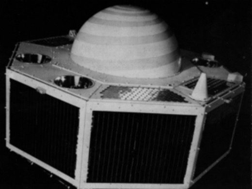
Geodetic Earth Orbiting Satellite/Geodynamics Experimental Ocean Satellite program (GEOS) was a US National Geodetic Satellite Program (NGSP) operated by NASA to experimentally test the tracking system behaviour of three spacecraft. This supported the unification of the world's tracking datums to a 5-10 m level of uncertainty with respect to the geocenter, and helped define the structure of Earth's irregular gravitational field. The mission consisted of three spacecraft: GEOS-1 (Geodetic Earth Orbiting Satellite-1) which operated from November 1965 to January 1968, GEOS-2 (Geodetic Earth Orbiting Satellite-2) which operated from January 1968 to January 1970, and GEOS-3 (Geodynamic Experimental Ocean Satellite) which operated from April 1975 to July 1979.
Quick facts
Overview
| Mission type | EO |
| Agency | NASA |
| Mission status | Mission complete |
| Launch date | 06 Nov 1965 |
| End of life date | 01 Jul 1979 |
| Measurement domain | Gravity and Magnetic Fields |
| Measurement category | Gravity, Magnetic and Geodynamic measurements |
| Measurement detailed | Geoid |
| Instrument type | Gravity instruments |
| CEOS EO Handbook | See GEOS (Geodetic Earth Orbiting Satellite) NASA summary |
Summary
Mission Capabilities
The GEOS-1 instrument payload included an optical beacon system used for geometric geodesy, laser corner reflectors to determine the spacecraft’s range and angle, and a radio doppler system to help establish the structure of the Earth's gravitational field. GEOS-2 carried an identical geodetic instrumentation payload to GEOS-1, adding a C-band Radar Transponder used for experimental range radar calibration, a Precipitating Electron Detector to measure electrons in the energy range 2-10 keV, and a magnetometer which primarily served as an attitude sensor. The instrumentation onboard GEOS-1 and GEOS-2 helped researchers define the structure of the Earth's irregular gravitational field, and refine the locations and magnitudes of the large gravity anomalies.
GEOS-3 was an important stepping stone between the National Geodetic Satellite Program (NGSP) and the Earth and Ocean Physics Application Program. In addition to furthering understanding of Earth's shape and gravitational field, GEOS-3 hosted instrumentation designed to obtain data about deep ocean tides, sea state and current structure. The GEOS-3 payload included a Radar Altimeter (ALT) to provide precise satellite-to-ocean surface height measurements and a Retroreflector Array (RRA) which allowed a ground-based laser to provide range information.
Performance Specifications
GEOS-1 and GEOS-2 instrumentation were designed to operate simultaneously to locate observation points in a 3D Earth centre of mass coordinate system within an accuracy of 10 m. The Radio Doppler system hosted on both satellites was used to establish the structure of the Earth's gravitational field with an accuracy of approximately five parts in 100 million. The GEOS-3 Radar Altimeter provided sea surface height measurements with a 0.5 m range precision in Global mode and 0.2 m in Intensive mode.
All three GEOS satellites operated in Low Earth Orbit (LEO). GEOS-1 followed a 1,114 km by 2,273 km elliptical orbit with an inclination of 59.4°, and a period of 120.3 minutes. GEOS-2 followed a 1,079 km by 1,572 km elliptical orbit with an inclination of 105.8° and a period of 112.20 minutes. GEOS-3 followed an 816 km by 850 km elliptical orbit with an inclination of 115.0° and a period of 101.52 minutes.
Space and Hardware Components
All three GEOS spacecraft were gravity-gradient-stabilised, solar-cell powered satellites built by the Applied Physics Laboratory of John Hopkins University with on-orbit masses of 387 kg for GEOS-1, 469 kg for GEOS-2, and 340 kg for GEOS-3. Both the GEOS-1 and GEOS-2 spacecrafts featured a SECOR (Sequential Collation of Range) radio range system, and used a Minitrack System in combination with a Range and Range-Rate System to establish orbit and determine the range and the radial velocity of the spacecraft. Communications were via a turnstile antenna for VHF and UHF frequencies, and separate antenna for Earth-viewing 324 MHz Doppler, C-band, and S-band transponders.
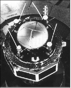
The GEOS-3 spacecraft hosted a parabolic reflector for a radar altimeter on the flat bottom side, a metal ribbon gravity-gradient boom, and passive laser retroreflector cubes mounted in a ring around the parabolic reflector.
GEOS (Geodetic Earth Orbiting Satellite), NASA - GEOS Program
GEOS was a US National Geodetic Satellite Program (NGSP). The NASA mission initiative of three spacecraft was of a study nature to test tracking system behavior experimentally and to unify the world's tracking datums to the 5-10 m level of uncertainty with respect to the geocenter. In this context the GEOS acronym has two definitions, 1) Geodetic Earth Orbiting Satellite, and 2) Geodynamics Experimental Ocean Satellite. 1)
Satellite | Other Designations | Launch | Orbit |
GEOS-1 (Geodetic Earth Orbiting Satellite) | GEOS-A, Explorer 29 | Nov. 6, 1965, Cape Canaveral, FLA | 1,114 x 2,273 km x 59.4º |
GEOS-2 (Geodetic Earth Orbiting Satellite) | GEOS-B, Explorer 36 | Jan. 11, 1968 from VAFB, CA | 1,079 km x 1,572 km x 105.8º |
GEOS-3 (Geodynamics Experimental Ocean Satellite) | GEOS-C | April 9, 1975 from VAFB, CA | 816 km x 850 km x 115.0º |
GEOS-1 (Geodetic Earth Orbiting Satellite) / Explorer 29
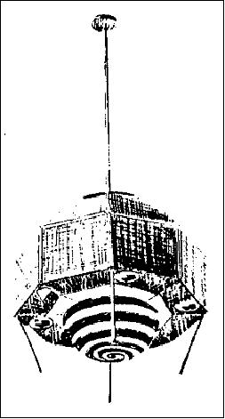
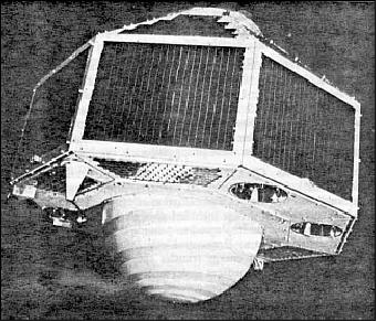
The NASA GEOS-1 spacecraft, built by JHU/APL, was a gravity-gradient-stabilized, solar-cell powered satellite (387 kg of on-orbit mass), designed exclusively for geodetic studies. It was the first successful active spacecraft of the National Geodetic Satellite Program. Instrumentation included 1) four optical beacons, 2) laser reflectors, 3) a radio range transponder, 4) Doppler beacons, and 5) a range and range rate transponder.
These were designed to operate simultaneously to fulfill the objectives of locating observation points (geodetic control stations) in a three dimensional Earth center-of-mass coordinate system within 10 m of accuracy, of defining the structure of the Earth's irregular gravitational field and refining the locations and magnitudes of the large gravity anomalies, and of comparing results of the various systems onboard the spacecraft to determine the most accurate and reliable system. Acquisition and recording of data were the responsibility of the GSFC Spaceflight Tracking and Data Network (STDN). Ten major observing networks were used. 2)
Launch
Spacecraft launch on Nov. 6, 1965 on a Delta vehicle from Cape Canaveral, FLA.
Orbit: Elliptical orbit, perigee= 1113 km, apogee=2275 km, inclination=59.3º, eccentricity = 0.07193, period = 120.3 minutes.
Sensor Complement
Optical Beacon System
The optical beacon system, used for geometric geodesy, consisted of four xenon 670 W (1580 candle-second/flash) flash tubes housed in reflectors. These tubes were programmed to flash sequentially in a series of five or seven flashes at times when they could be optically observed from Earth. Observations were made by STDN and SPEOPT MOTS 1 m and 0.6 m cameras, SAO (Smithsonian Astrophysical Observatory) Baker-Nunn and geodetic 0.9 m cameras, USAF PC1000 cameras, and U.S.C&GS (Coastal and Geodetic Survey) BC-4 cameras. Telescopic cameras at three or more stations simultaneously photographed the flashes against the star background. Satellite position and angle of elevation from each station could then be determined by using star charts as guides. If two of the three stations had known positions, the coordinates of the third could be calculated by triangulation. The instrument operated satisfactorily from November 18, 1965, to December 1, 1966, when command capability was lost.
Laser Tracking Reflector
Laser corner reflectors composed of fused quartz cubes with silvered reflecting surfaces, were used for determining the spacecraft’s range and angle. The 322 cubes were mounted on fiberglass panels on the bottom rim of the spacecraft and provided a total reflecting area of 0.18 m2. The reflectors conserved the narrow beamwidth of incoming light and reflected a maximum signal to the ground, almost exactly to where it originated. About 50% of the light which struck the prism area at a 90º angle was reflected within a beam of 20 arcseconds. Reflected light received by ground telescopes was amplified by a photomultiplier tube that converted the optical impulse to an electrical signal. The time for the beam to return to the Earth was recorded by a digital counter. The reflected laser pulse was also photographed against the stellar background. Total time traveled by the light pulses was also considered in the optical laser tracking system.
Radio Doppler System
The Doppler technique of timing and measuring the frequency shift of radio transmissions from a moving S/C was used to help establish the structure of the Earth's gravitational field to an accuracy of about five parts in 100million. Three transmitters were operated on frequencies of 162, 324, 972 MHz. Timing markers (bursts of 60º phase modulation) of 0.3 s duration once each minute were carried by the 162 and 324MHz transmitters. Synchronization of the markers was to an accuracy of 0.4 ms. The system began operating during November 1965. The 972 MHz Doppler operated until January 14, 1967, when an intermittent command system response caused a permanent turn-off. The two lower frequency beacons operated continuously until December 1967, when operations became intermittent and progressively weaker. Operations were terminated on Jan. 15, 1968.
SECOR (Sequential Collation of Range)
The system operated by the Army Map Service (AMS) was used for the S/C radio range system. A 3.6 kg transponder received and retransmitted ground radio signals (421 MHz receiver and 224.5 and 449.0 MHz transmitter). Ground-based equipment included phase-modulated transmitters, range-data receivers, and electronic phase-meters. The transponder provided valuable ranging data for four US SECOR stations to make possible inter-comparison tests from December 29, 1965, to May 1, 1966. Inter-datum and inter-island ties were completed from Tokyo to Hawaii using data from SECOR tracking stations and other geodetic observations made between May 24, 1966, and February 8, 1967. The transponder failed on February 8, 1967.
Radio Range/Rate System
Objective: Measurement of range and the radial velocity of the S/C by making phase shift and Doppler measurements. The onboard transponder, which operated on 2271 (receiver) and 1705 MHz (transmitter), and a conical antenna were the spacecraft components of the NASA/GSFC Range and Range/Rate System. The antenna, mounted on the Earth-facing portion of the S/C, could receive and transmit data. Its beam width was 150º. Data received from this instrument by three S-band stations were used to augment other geodetic data and to provide a comparison of this system with others used in tracking the S/C. The command system failure occurred on December 1, 1966.
Minitrack System
The minitrack interferometer tracking system (136 MHz) was used in combination with the NASA Range and Range/Rate System to establish the GEOS-1 orbit. Raw data from the two systems were used for early orbit determinations and routine orbit updating. Minitrack acquired 16,271 data points (station axis crossings). The Minitrack stations also participated in mutual visibility events that involved tracking with other stations for tracking system intercomparison experiments. The system operated nominally from Nov. 6, 1965, until January 14, 1967.
GEOS-2 (Geodetic Earth Orbiting Satellite) / Explorer 36
GEOS-2 is the second satellite in NASA's GEOS series (built by JHU/APL). Objectives: optimization of optical station visibility periods and provision of complementary data for inclination-dependent terms established by GEOS-1 gravimetric studies. GEOS-2 is a gravity-gradient-stabilized, solar-cell-powered spacecraft (469 kg of on-orbit mass) that carried electronic and geodetic instrumentation. The geodetic instrumentation systems included:
- Four optical beacons
- Two C-band radar transponders
- A passive radar reflector
- A sequential collation of range radio range transponder
- A range and range rate transponder
- Laser reflectors
- Doppler beacons.
- Non-geodetic systems included a laser detector and a Minitrack interferometer beacon.
Launch
The spacecraft launch was on Jan. 11, 1968 on a Delta vehicle from VAFB, CA (the spacecraft is also known as Explorer 36).
Orbit: Elliptical polar retrograde orbit, perigee=1082 km, apogee=1570 km, inclination = 105.8º, eccentricity = 0.03165, period = 112 minutes.
Mission Status
Operational problems occurred in the main power system, optical beacon flash system, and the spacecraft clock, and adjustments in scheduling resulted in nominal operations. 4) 5)
Sensor Complement
Optical Beacon System
Identical system as flown on GEOS-1. Data were obtained until Jan. 31, 1970.
Laser Tracking Reflector
Identical system as flown on GEOS-1.
Radio Doppler System
Identical system as flown on GEOS-1. The US Navy Doppler Tracking Network (TRANET) monitored the spacecraft for Doppler data. Observations made from three or more known stations allowed deduction of orbital parameters.
SECOR (Sequential Collation of Range)
Identical system as flown on GEOS-1. The range measurements were made by measuring the phase shift of the ranging sidetones that modulated the CW carrier. By using trilateration techniques, the unknown position of one of the four stations could be accurately determined.
RadioRange/Rate System
Identical system as flown on GEOS-1. The system is also known under the name of GRARR (Goddard Range and Range Rate).
C-band Radar Transponder
The system was used for experimental range radar calibration and data recording to determine the accuracy of the system for geometric and gravimetric investigations. For redundancy, two transponders, each operating on 5690 MHz (receiver) and 765 MHz (transmitter) were carried on the S/C. One transponder had a 5 ms interval time delay, and the other had a near-zero internal delay that allowed for real-time identification by the C-band participants. The transponders were operated on a select-call basis to conserve S/C power. A C-band passive reflector was used in conjunction with the transponders for precise calibration of the internal time delay and to provide passive C-band tracking capabilities.
Minitrack System
Identical system as flown on GEOS-1.
Precipitating Electron Detector
The instrument consisted of an electrostatic deflection device and channeltron detector intended to measure electrons in the energy range 2-10 keV.
Magnetometer
The instrument consisted of a uniaxial fluxgate magnetometer oriented perpendicular to the orbital plane. Although the principal function of the magnetometer was to serve as an attitude sensor, a very limited amount of scientifically useful data on fluctuations in the range 0.03 to 3.0 cps were obtained through use of a filter.
GEOS-3 (Geodynamic Experimental Ocean Satellite)
The GEOS-3 spacecraft was renamed to ”Geodynamic Experimental Ocean Satellite” to emphasize its specific mission in NASA's Earth and ocean physics program while retaining the GEOS acronym. GEOS-3 is the first dedicated radar altimeter mission of its kind (launch 1975) within NASA's series of geodetic missions. GEOS-3 served to provide the stepping stone between the National Geodetic Satellite Program (NGSP) and the Earth and Ocean Physics Application Program.
The mission objectives were to perform a satellite altimetry experiment in orbit, to support further the calibration and position determination of NASA and other agency C-band radar systems, and to perform a satellite-to-satellite (SST) tracking experiment with the ATS-6 [Application Technology Satellite (NASA GEO satellite series prior to GOES). ATS-6 demonstrated the technology for tracking and data relay satellites which led to the TDRSS program] spacecraft using an S-band transponder system. This system was also used for periodic GEOS-3 telemetry data relay through ATS-6, to support further the intercomparison of tracking systems, to investigate the solid Earth dynamic phenomena through precision laser tracking, to refine further orbit determination techniques and determine inter-datum ties and gravity models, and to support the calibration and position determination of NASA Spaceflight Tracking and Data Network (STDN) S-band tracking stations. The objectives also included defining the structure of the Earth's irregular gravitational field and refining the locations and magnitudes of the large gravity anomalies, comparing results of the various systems onboard the spacecraft to determine the most accurate and reliable system, and mapping the ocean surfaces.
Application: Determination of oceanographic and geophysical parameters, satellite altimetry. Estimation of significant wave height. Geometric, gravimetric and other geodetic investigations. First estimations of surface wind speeds with altimeter data. Provision of the first altimetry data set for some areas of the world's oceans (time period: 1975-1979).
Spacecraft
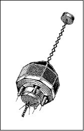
The GEOS-3 spacecraft was designed and built by JHU/APL (the Applied Physics Laboratory of the Johns Hopkins University) Laurel, MD. The S/C structure was an octahedron, topped by a truncated pyramid, with a parabolic reflector for a radar altimeter on the flat bottom side. A metal ribbon gravity-gradient boom with end mass extended upward approximately 6.1 m from the top of the pyramid. Passive laser retroreflector cubes were mounted in a ring around the parabolic reflector with the normal vector from each cube facing 45º outward from the direction of the Earth. The spacecraft dimension across the flats of the octahedron was 1.22 m, the spacecraft was 1.11 m high. S/C on-orbit mass = 340 kg. 6) 7) 8)
RF communications: A turnstile antenna for VHF and UHF frequencies and separate antennae for Earth-viewing 324 MHz Doppler, C-band, and S-band transponders were mounted separately on flat surfaces next to the parabolic reflector. - Due to the lack of an onboard data recorder, the coverage was limited to areas near ground receiving stations mainly around the USA. The western North Atlantic is the only geographic region where nearly continuous altimeter data are available.
NASA center responsible | Wallops Flight Center , Wallops, VA |
S/C shape | Octahedron topped by a truncated pyramid with a gravity gradient boom extending from one end and a doppler beacon from the other |
S/C dimensions | 1.32 m in width, 0.81 in length (6 m maximum overall length) |
S/C mass | 340 kg |
Power source | Solar cells plus NiCd batteries |
S/C stabilization | Gravity-gradient stabilized |
RF communications | C-band antenna (2), S-band antenna, ATS relay antenna, VHF antenna Doppler beacon |
Launch
April 9, 1975 on a Thor-Delta launch vehicle from VAFB, CA, USA.
Orbit: Non-sun-synchronous, near-circular polar retrograde orbit, apogee = 856 km, perigee = 824 km, inclination = 115º, period =101.82 minutes.

Mission Status
Operation of the satellite for over 3 1/2 years until July 1979.
Sensor Complement
ALT (Radar Altimeter)
ALT is a Ku-band instrument, designed and developed by JHU/APL and by the AESD (Aerospace Electronic Systems Department) of General Electric Company. ALT is a multimode radar system with two distinct data-gathering modes (global and intensive). The global mode used a long pulse (200 ns) with two altimetric readings per second, while the intensive mode used a short pulse (12 ns) with six readings per second (since GEOS-3 all altimeters have been using the chirp technique of pulse compression). Both modes operated at 13.9 GHz frequency, used a parabolic antenna, had a maximum range acquisition time of 6 s, and had an altitude granularity of ± 0.2 m.
The GEOS-3 altimeter consisted of the following major subsystems:
• Magnetron transmitter for the long pulse (global) mode
• TWT (Traveling Wave Tube) transmitter for the short pulse (intensive) mode
• Antenna
• Receiver
• Signal processor
• Built-in test/calibration system.
ALT is the first radar altimeter to provide sea surface height measurements (50 cm range precision in the global mode and 20 cm in the intensive mode). This radar altimeter was of S-193 heritage on the Skylab mission (1973 - the Skylab altimeter recorded a couple of tracks and revealed the existence of trenches in the marine geoid); however, with improved accuracy and the ability to operate over extended areas for greater periods of time, thereby providing the capability of examining the Earth over longer arcs and observing extensive ocean areas.
Instrument calibration: ALT featured two self-test/calibration modes for use in on-orbit functional test and instrument calibration. The major calibrations considered necessary for the built-in test/calibration system were time delay (bias), AGC/gain, and waveform calibration. Internally generated signals were provided for calibration. A 10 second time delay (bias) test was performed in each mode to determine the bias to within the required 1 m. In each mode, a two-point AGC/gain calibration was obtained using IF reference pulses. For waveform calibration, controlled video waveforms were used in both modes. 9) 10)
The ALT instrument operated nearly continuously from launch to July 1979, providing at its time the most complete altimetry data set collected over the oceans, and demonstrating the feasibility of directly measuring geodetic, oceanographic, and geophysical parameters through the reduction and analysis of the altimeter height measurements and the shape and structure of the return waveform. In addition, the altimeter was shown to be capable of providing valid measurements over land and sea ice. 11)
The emerging availability of GEOS-3 altimetry data triggered a lot of interest in the mid-1970s. As a consequence, the JPL decided to prove definitively the potential of spaceborne missions for oceanography by building SEASAT (a dedicated satellite for oceanography, launch June 27, 1978) with altimeter, scatterometer (to measure wind), SAR and passive radiometer.
RRA (Retroreflector Array)
RRA was built at JHU/APL consisting of a spaceborne laser retroreflector subsystem and ground-based laser-ranging systems (provision of precision satellite-ranging data). RRA is an annulus of 57 cm in diameter consisting of 264 quartz cube corner reflectors mounted on a 45º conic frustum.
When illuminated by a laser light pulse from the ground, each retroreflector cube in the array reflected the light ray back to a special telescope receiver on the ground. The reflected light was picked up by the telescope, and the optical impulses converted to an electrical signal. A digital counter recorded the time when the light beam was returned to the ground. The total travel time of the light pulses, from ground to satellite and back to the ground, measured the distance to the satellite, thus forming the basis of the satellite optical laser system. The following observational systems acquired the necessary data: NASA/Wallops Laser Ranging Systems, SAO (Smithsonian Astrophysical Observatory) Laser Ranging Systems, GSFC Laser Ranging Systems, and other national and international laser stations.
The orbit of GEOS-3 was computed from laser ranges and one-way downlink Doppler measurements, using a tracking network (the same network as used for TRANSIT). The accuracy of the orbit for the radial component was about 2 m. Nevertheless, the GEOS-3 orbit determination effort and innovative analysis techniques yielded new maps of the marine geoid and sea-level variability.
Note: The passive RRA tracking feature of SLR (Satellite Laser Ranging) was used far beyond the operational life of GEOS-3.
Doppler System GEOS-3
Doppler System GEOS-3 (US Navy) of GEOS-1 heritage, consisting of two spaceborne transmitters and ground Doppler receiving stations. The dual frequencies (162 and 324 MHz) were coherently related and utilized in conjunction with ground Doppler receiving stations to obtain precision satellite range-rate data. The dual frequencies were generated by a highly stable oscillator driving two frequency multipliers. Both frequencies were used simultaneously to provide comparison data of the effect of the ionosphere on the signals. Observations made from three or more known stations allowed deduction of orbital parameters. Data rate = 15.6 kbit/s or 1.56 kbit/s.
S-Band Tracking System
The transponder subsystem consisted of a single-channel transponder, a power amplifier, a diplexer, and an Earth-viewing and ATS-viewing antenna system. The transponder operated in the following three modes: 1) satellite-to-satellite tracking, 2) direct unified S-band (ground-station tracking of GEOS-3), and 3) direct GRARR (Goddard Range and Range Rate) ground-station tracking of GEOS-3.
C-band Radar Transponder
Identical to the system on GEOS-2.
SST (Satellite-to-Satellite Tracking)
The SST experiment consisted of: 12)
1) the ground-based ATS ranging system
2) the wideband communication transponder on the ATS-6 geosynchronous spacecraft, and
3) the ranging transponder on the LEO satellite.
References
1) “National Geodetic Satellite Program,” NASA Special Publication SP-365, Washington, DC, 1977
2) http://cddis.gsfc.nasa.gov/926/egm96/geos1.html
3) http://rammb.cira.colostate.edu/dev/hillger/scientific.htm#explorer
4) http://cddis.gsfc.nasa.gov/926/egm96/geos2.html
5) J. G. Marsh, B. C. Douglas, S. M. Klosko, ”A Global Station Coordinates Solution Based Upon Camera and Laser Data-GSFC 1973”, The Use of Artificial Satellites for Geodesy and Geodynamics, Proceedings of the International Symposium, Athens, Greece, May 14-21, 1973; Edited by George Veis. Athens: National Technical University of Athens, 1974, pp. 749-800
6) H. R. Stanley, “The GEOS 3 Project,” Journal of Geophysical Research, July 30, 1979, pp. 3779-3783
7) ”GEOS 3 Mission Operations Report,” NASA, E-855-75-01, Apr. 8, 1975
8) http://ilrs.gsfc.nasa.gov/satellite_missions/list_of_satellites/geos_general.html
9) A. B. Watts, “On geoid heights derived from Geos-3 altimeter data and flexure of the lithosphere along the Hawaiian-Emperor seamount chain,” Journal of Geophysical Research, Vol. 38, 1979, pp. 119-141.
10) N. E. Huang, C. D. Leitao, C. G. Parra, “Large scale Gulf Stream Frontal study using GEOS-3 radar altimeter data,” Journal of Geophysical Research, Vol. 83, 1978, pp. 4673-4682
11) R. F. Gasparovic, R. K. Raney, R. C. Beal, “Ocean Remote Sensing Research and Applications at APL,” Johns Hopkins APL Technical Digest, Vol. 20, No 4, 1999, pp. 600-610
12) P. Argentiero, et al., “Results of GEOS 3/ATS-6 Satellite-to-Satellite Tracking Orbit Determination Experiment,” Journal of Geophysical Research, Vol. 84, No. B8, 1979, pp. 3921-3925
The information compiled and edited in this article was provided by Herbert J. Kramer from his documentation of: ”Observation of the Earth and Its Environment: Survey of Missions and Sensors” (Springer Verlag) as well as many other sources after the publication of the 4th edition in 2002. - Comments and corrections to this article are always welcome for further updates (eoportal@symbios.space).