HY-2 (Haiyang-2) / Ocean-2
EO
Atmosphere
Ocean
Operational (extended)
The Haiyang-2 (HY-2) satellite series is a second generation ocean observation satellite, managed by the China National Space Administration (CNSA) and the Chinese Academy of Space Technology (CAST). It is the follow-on mission to the first generation, HY-1A and HY-1B. HY-2’s primary objective was to measure ocean dynamic and regional environmental trends in the microwave spectral range. Further, parameters such as marine wind vector, marine surface heat and Sea Surface Temperature (SST) aid aero-marine forecasts for the prevention of, and relief in the event of, natural disasters. The first Haiyang satellite, HY-2A, was launched in August 2011, producing observational data until its service was terminated in December 2021. The satellite series consists of eight satellites with four currently in operation and four more planned to be launched by 2025.
Quick facts
Overview
| Mission type | EO |
| Agency | CAST, NSOAS |
| Mission status | Operational (extended) |
| Launch date | 16 Aug 2011 |
| Measurement domain | Atmosphere, Ocean, Snow & Ice |
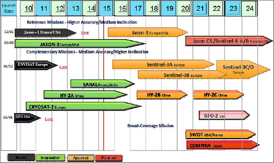
| Measurement category | Surface temperature (ocean), Atmospheric Humidity Fields, Ocean topography/currents, Sea ice cover, edge and thickness, Ocean surface winds, Ocean wave height and spectrum |
| Measurement detailed | Atmospheric specific humidity (column/profile), Sea surface temperature, Sea-ice cover, Wind speed over sea surface (horizontal), Significant wave height, Sea level, Ocean dynamic topography |
| Instruments | SCAT, MWRI, ALT, DGXX-S, DGXX |
| Instrument type | Scatterometers, Precision orbit, Imaging multi-spectral radiometers (passive microwave), Radar altimeters |
| CEOS EO Handbook | See HY-2 (Haiyang-2) / Ocean-2 summary |
Summary
Mission Capabilities
The primary instrument onboard the HY-2 series is the Microwave Radiometer Imager (MWRI). MWRI is a multichannel conical radiometer, operating with a nadir viewing angle and observing ocean surfaces and coastal zones. This data was subsequently used for pollution monitoring, as well as evaluation of estuary and navigation routes.
HY-2 satellites also contain a Radar Altimeter (RA), conducting active, onboard analysis to estimate altitude by transmitting a dual frequency (Ku-band and C-band) signal. The Ku-band Rotational Fan-beam Scatterometer (KU-RFSCAT), known as SCAT, made accurate measurements of surface wind. The French designed, Determination Orbite Radio Positionnement Integres Satellite system (DORIS) was only onboard on HY-2A. DORIS utilised Doppler frequency shift in order to derive observation satellite orbits and relevant ground positions.
Performance Specifications
MWNIR images across five different channels, with frequencies ranging from 6.6 GHz, up to 37 GHz. The total swath width is 1600 km, and the ground resolution steadily decreases across the five channels, with the low frequency channel observing at 100 km and the high frequency channel at 18 km. The RA images with a ground footprint of 16 km and central transmission frequencies of 13.58 GHz and 5.25 GHz. SCAT has the capability to measure wind speeds in the range 2 m/s - 24 m/s, with a corresponding accuracy of 10%. SCAT can also infer the wind direction within a range of ±20º.
HY-2A traversed a near sun-synchronous frozen orbit, travelling at an altitude of 971 km, an inclination of 99.3º and a period of 104.5 minutes.
HY-2B and HY-2D are both in sun-synchronous orbits at an altitude of 963 km with an orbital inclination of 99.3º.
HY-2C traverses an inclined, non-sun-synchronous orbit at an altitude of 957 km with an orbital inclination of 66º.
HY-2E, HY-2F, HY-2G and HY-2H are all planned to be in a sun-synchronous orbits with an orbital altitude of 963 km, and orbital inclination of 99.3º and will have a repeat cycle of 14 days.
Space and Hardware Components
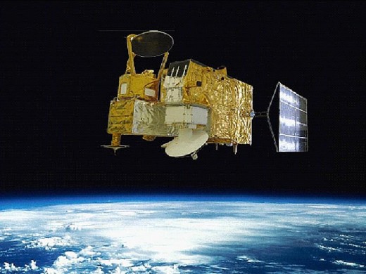
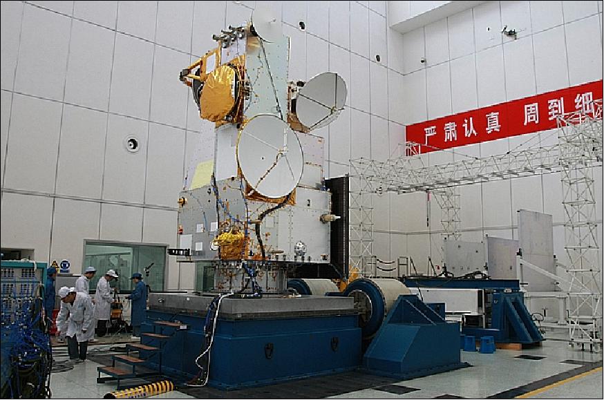
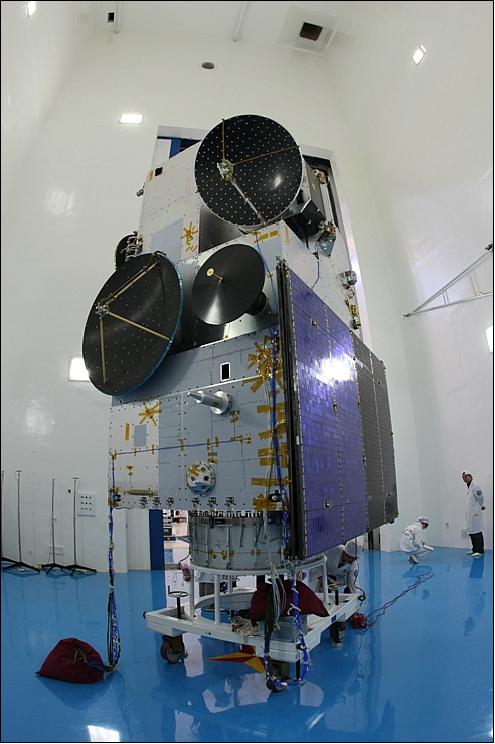
The spacecraft of the entire HY-2 series of satellites is identical. The HY-2 bus, designed by the Chinese Organisation, State Oceanic Administration (SOA), was sponsored by the Chinese State Authorities. The spacecraft was three-axis stabilised and used the CAST968 satellite platform. Designed and manufactured by DFH (Dongfanghong Satellite Corporation Ltd.), the nominal lifetime was three years, but the mission outfirmed this, continuing for just over a decade.
RF communications were employed on the HY-2 satellite, with payload data downlink transmitted in the X-band and spacecraft control uplink in the S-band.
HY-2 (Haiyang-2) / Ocean-2
Overview Spacecraft Launch Mission Status Sensor Complement References
HY-2 is a second generation ocean observation/monitoring satellite series approved by CNSA (China National Space Administration) Beijing in Feb. 2007. The HY-2A mission represents a follow-up of the HY-1A and HY-1B missions.The HY-2 series of satellites consists of eight satellites in total, HY-2A, HY-2B, HY-2C, HY-2D, HY-2E, HY-2F, HY-2G, HY-2H, of which three are operational, four are planned to be launched and one has been decommissioned as of 2023.
The overall objective of HY-2 is the measurement of ocean dynamic and environmental parameters in the microwave region (i.e., all weather observations). The requirements call also for the collection of data on marine wind setup (wind vector), marine surface height, and SST (Sea Surface Temperature), along with aero-marine forecasts for the prevention and relief of disaster.1) 2) 3)
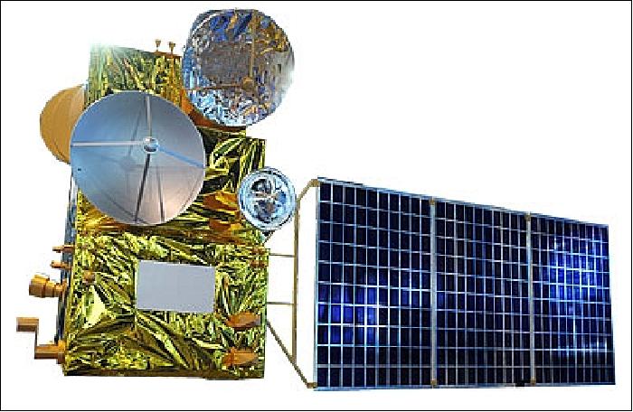
Spacecraft
The development of HY-2A, the first of the series of HY-2 series of satellites sponsored by the State Oceanic Administration (SOA), was approved by Chinese authorities on January, 2007. The spacecraft is three-axis stabilized using the CAST968 satellite platform. The spacecraft is being developed by the DFH (Dongfanghong Satellite Corporation Ltd.), a spin-off company of CASC (China Aerospace Science &Technology Corporation), Beijing, China.
The spacecraft has a pointing precision of < 0.1º in pitch, roll and yaw and a pointing knowledge of < 0.05º. Like its predecessors, HY-2A is a spacecraft with a mass of ~ 1500 kg. The HY-2A spacecraft will be operated by NSOAS (National Satellite Ocean Application Service) for a nominal lifetime of 3 years. 4)
Launch
The HY-2 spacecraft have all been launched onboard Long March 4B vehicles. HY-2A and HY-2B were launched from Taiyuan Satellite Launch Center, Shanxi Province, China on August 15, 2011 and October 25, 2018 respectively.
HY-2C and HY-2D were launched from the Jiuquan Satellite Launch Centre in the Gobi Desert, Inner Mongolia, China. HY-2C was launched on September 21, 2020. This was followed by the launch of HY-2D on May 19, 2021.
The rest of the HY satellite series, HY-2E, HY-2F, HY-2G, and HY-2H, are planned to be launched by the end of 2025.
Orbit: The HY-2 satellites are in all in different orbits to cover a large area of the Earth’s ocean.
HY-2A is in a near sun-synchronous frozen orbit, with altitude = 971 km, inclination of 99.3º and period = 104.45 minutes. Equator crossing time on descending node at 6:00 hours, repeat cycle: two phase (14 days and 168 days).
HY-2B and 2D are in a Sun-synchronous orbit with an altitude of 963 km, inclination of 99.3º, and have a repeat cycle of 14 days.
HY-2C is in an inclined, non-sun-synchronous orbit with an altitude of 957 km and an inclination of 66º.
HY-2E, HY-2F, HY-2G and HY-2F are also planned to be in a sun-synchronous orbit with an altitude of 963 km, inclination of 99.3º and will have a repeat cycle of 14 days.
RF communications: The downlink of payload data is in X-band. Spacecraft monitoring and control is being done in S-band. Real-time transmission to X-band stations in Beijing, Hangzhou, SanYa and Mudanjiang.5) 6) 7)

Mission Status
• May 19, 2021: HY-2D was launched aboard a Long March 4B launch vehicle from the Jiuquan Satellite Launch Centre in the Gobi Desert
• September 21, 2020: HY-2C was launched aboard a Long March 4B launch vehicle from the Jiuquan Satellite Launch Centre in the Gobi Desert
• October 25, 2018: HY-2B was launched aboard a Long March 4B launch vehicle from the Taiyuan Satellite Launch Center, Shanxi Province, China
• According to WMO, the HY-2A mission is operational in 2016 in its 5th year on orbit. 8)
• Oct. 27, 2015: Hurricane Patricia formed on October 20 as a tropical depression, near the Gulf of Tehuantepec, off Guatemala, in the tropical Pacific. It rapidly strengthened up to Category 5 and was classified as the most intense tropical hurricane ever recorded in terms of barometric pressure (879 mbar) in the Western Hemisphere. It significantly weakened while approaching the Mexico coasts. Nevertheless, dangerous flooding and landfall occurred from Mexico to Texas and Louisiana. 9)
- The strong El Niño currently occurring in the Pacific ocean with warm waters helps create initial conditions for tropical storms and as a gasoline to add up the energy in storms that makes them intensify.
- Altimetry satellites have made a significant contribution to the prediction of trajectories and intensities by collecting data on sea surface height, wind speed and wave height. CryoSat-2 overflew the hurricane path just 3 hours before. It revealed wave heights of more than 7 m and wind speed more than 28 m/s (>100 km/h).
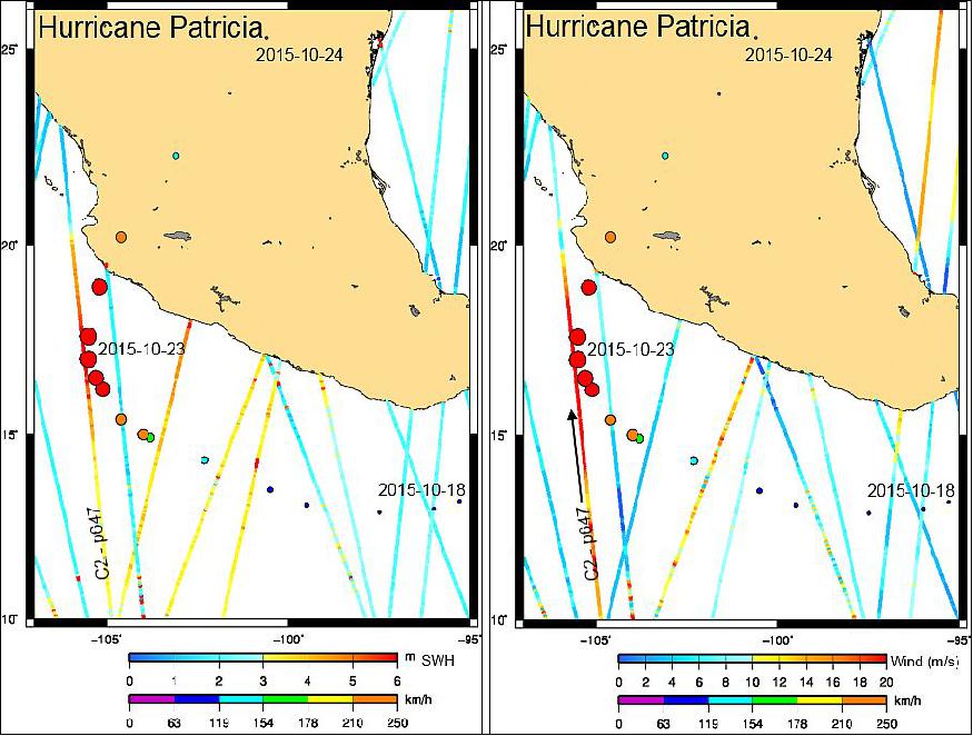
Legend to Figure 5: The hurricane's path is shown by colored circles (the intensity scale measures the wind speed of the typhoon in km/h): purple for a tropical depression, blue for Category 1, green for Cat. 2, yellow for Cat. 3, orange for Cat.4 and red for Cat. 5. The dates near the path indicate the date when the hurricane passed. The CryoSat-2 pass 647 measured the highest wind speed at 2015-10-23 08:40:07, a few hours before the typhoon reached this area.
• August 2015: The HY-2 satellite has the ability to image large planetary areas in all weather during day and night. The HY-2 satellite altimeter provides sea surface height, significant wave height, sea surface wind speed and polar ice sheet elevation, while the HY-2 satellite scatterometer provides sea surface wind fields. At the same time, other oceanic and atmospheric parameters such as sea surface temperature and wind speed, water vapor and liquid water content can also be obtained by its onboard scanning microwave radiometer. 10)
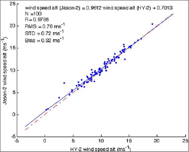
- The data of NDBC (National Data Buoy Center) of NOAA, the data of NCEP (National Centers for Environmental Prediction) and Jason-2 data have been used to assess the performance of HY-2 independently. The results show that the measurement accuracy of HY-2 is in accordance with the NDBC's and NCEP's for wind speed (field) and significant wave height. A cross comparison with Jason-2 data over the same period has been performed in order to compare the sea surface height and sea level anomaly of the HY-2 altimeter. The project found, that the precision of HY-2 sea surface heights is the same as those of Jason-2.
- Figure 6 gives a comparison of the wind speed between HY-2 and Jason-2 satellite radar altimeters. The results show that the HY-2 wind speed agrees very well with the Jason-2 wind speed.
- Scatterometer: The rain forest is usually regarded as one of the most stable targets on Earth's surface. The stability of HY-2 is also of importance and can be examined using rainforest observations. In order to verify the stability of the HY-2 scatterometer, the Amazon tropical rain forest region was selected as the study. The longitude range of this region is from -66ºE to -60ºE, while the latitude range is from -8ºN to -5.5ºN. The temporal coverage of the σ0 data is three days, from April 12 to April 24, 2014. Figures 7 and 8 give the σ0 scatter plots of this rain forest region.
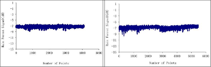
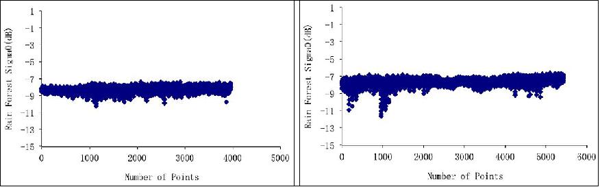
From the Figures 7 and 8, it can be seen that the σ0 measurements in this region fluctuate around a fixed mean value and the variation is very small, which indicates the stability of the instrument.
• The good performance of the HY-2A mission resulted to include the scatterometer data of HY-2 into the NWP (Numerical Weather Prediction) models of KNMI (Royal Netherlands Meteorological Institute) and those of the ECMWF (European Centre for Medium-Range Weather Forecasts). 11)
• In May 2015, the HY-2A satellite mission is operating nominally and already beyond its design life of 3 years. 12)
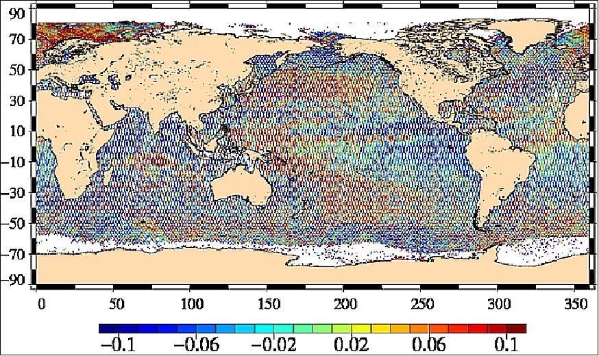
• January 2015: The HY-2A project team presents the first comprehensive result assessing HY-2A's altimeter data quality and the altimetry system performance using an improved HY-2A Geophysical Data Record (GDR) product (Institute of Geodesy and Geophysics reprocessed GDR product version A, GDR_IGGA). The main improvements include altimeter timing and waveform retracking, and tropospheric, ionospheric, and sea-state bias (SSB) corrections, which resulted in more accurate HY-2A sea surface height observations. Jason-2 altimeter observations are used for the cross calibration of the HY-2A altimeter over the oceans between ±60° latitude bounds, primarily due to the limitation of Jason-2 coverage. The statistical results from single- and dual-satellite altimeter crossover analysis demonstrated that HY-2A fulfills its mission requirements. The team uncovered a mean relative bias of -0.21 cm (with respect to Jason-2), and a standard deviation of 6.98 cm from dual-satellite crossover analysis. 14)
• The HY-2A spacecraft and its payload are operating nominally in 2014. 15) The SCAT (Ku-RFSCAT) instrument is carried on-board the HY-2A polar satellite, and its products have been operationally distributed by NSOAS (National Satellite Ocean Application Service) since October 2011. 16)
• The HY-2A spacecraft and its payload are operating nominally in 2013. The mission has been offering data to scientific users since the summer of 2012. Cross-overs of HY-2A along the period of time (2012-2013) with Jason-2 and CryoSat-2 are being investigated. 17) 18)
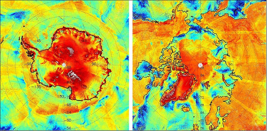
• Sigma 0 distribution at the polar regions obtained by HY-2A SCAT in 2013. 19)
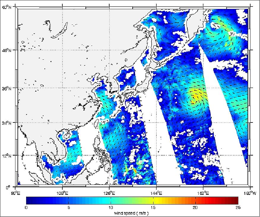
• In a study performed in 2013, a comparison of wind field measurements from the HY-2A Scatterometer and the U.S. National Data Buoy Center (NDBC)'s moored buoys was performed. These comparisons were made in the Pacific Ocean and the Atlantic Ocean over a one month period of August 2012. The SCAT wind speed retrieval agreed well with the buoy measurements, with mean differences of -0.74 m/s and standard deviations of 1.52 m/s. The results (Figure 11) indicate that the SCAT-derived ocean surface wind speeds are as accurate as other scatterometers, such as QuikScat and ASCAT. 20)
However, the wind direction retrieval of SCAT still has some problems which need to be investigated in the future. Further analysis is underway to include more HY-2A data especially those in the higher wind domain, and validation results against ECMWF reanalysis and SAR winds.
• Sept. 2012: The HY-2A project has demonstrated that the mission fulfills the requirements of high precision altimetry. In particular, it allows continuing the observation of the MSL (Mean Sea Level) variations at the same accuracy as ERS-1. The accuracy of SSH (Sea Surface Height) derived from GDR products of HY-2A, is about 8.5 cm. 21) 22)
• On March 2, 2012, control of the HY-2A spacecraft was handed over to SOA (State Oceanic Administration) by DFH of CASC. HY-2A has passed the commissioning phase and was declared "operational". HY-2 will work in collaboration with HY-1B, the Chinese oceanic surveying satellite with a launch of HY-1B on April 11, 2007. 23) 24)
• The HY-2A spacecraft is on its nominal mission orbit since October 1, 2011. Precise orbits are computed at CNES on the basis of 7 days arcs since the beginning of the mission (repeat cycle is 14 days).
• On August 31, 2011, the DORIS and GPS instruments were switched on and the first data obtained by DORIS show good results on the orbit determination. 25)
Sensor Complement
MWRI (Microwave Radiometer Imager)
MWRI is a multichannel nadir-viewing radiometer with the objectives to observe ocean surfaces and coastal zones for biological resources, pollution monitoring and prevention, and monitoring of estuaries, bays and navigation routes.
Wind speed | - Range: 7-50 m/s |
SST /Sea Surface Temperature) | - Range: 100-300 K |
Ice monitoring | - Edge: 15% |
Water vapor | Precision: 10% |
Center frequency (GHz) | 6.6 | 10.7 | 18.7 | 23.8 | 37 |
RF bandwidth (MHz) | 350 | 250 | 250 | 400 | 1000 |
Polarization | V,H | V,H | V,H | V | V,H |
Brightness temperature sensitivity (K) | 0.5 | 0.5 | 0.5 | 0.5 | 0.8 |
Calibration precision | 1 K @ 180~320 K | ||||
Swath width | 1600 km | ||||
Ground resolution (km) | 100 | 62 | 36 | 30 | 18 |
Dynamic range (K) | 3~350 | ||||
Receiver linearity | > 0.999 | ||||
Main beam coefficient | > 95% | ||||
Scanning mode | Conical scanning | ||||
RA (Radar Altimeter)
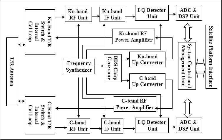
RA/HY-2 was designed and developed at NMRSL (National Microwave Remote Sensing Laboratory) of CSSAR (Center for Space Science and Applied Research), Beijing. RA is an active instrument, a dual-frequency (Ku-band and C-band) radar altimeter. The Ku-band portion of the instrument comes with a DDS (Direct Digital Synthesizer), creating LF-chirps (Low Frequency) with bandwidths of 320, 80 and 20 MHz. The bandwidth of the C-band is fixed at 160 MHz. A MCT (Model Compatible Tracker), in which both MLE (Maximum likelihood Estimate) algorithm and OCOG (Off Center of Gravity) algorithm cooperating in parallel, is used in RA/HY-2.
The user requirements call for:
- Sea surface precision: < 8 cm
- SWH (Significant Wave Height) range: 0.5-20 m; and an SWH precision of < 10 % or 0.5 m (whatever is greater).
Instrument: The RA instrument is comprised of the following elements: 27) 28) 29)
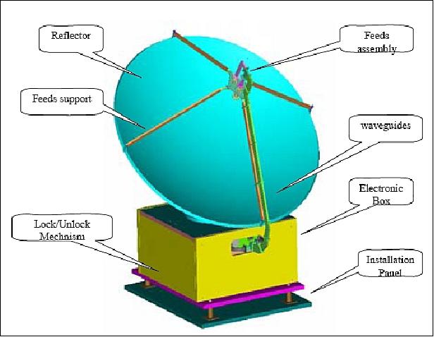
• Antenna: The antenna of RA/SCAT is a paraboloidal reflector antenna. The two frequencies will share the reflector with a dual-frequency feed. The antenna gain is greater than 42.5dB (Ku-band) and more than 32.5dB (C-band). The antenna looks to the nadir, and the pointing accuracy is 0.1º.
• T/R switch and internal calibration loop. This unit includes the T/R switch and the internal calibration loop.
• Frequency synthesizer: The frequency synthesizer provides all the frequency signal for the system, including the local oscillator frequency, the reference frequency and the clock signals.
• Transmitter: The transmitter consists of a DDS signal generator, the up-converter and the solid-state RF power amplifier.
• Receiver: The receiver consists of the LNA (Low Noise Amplifier), the down-converter, the deramp-mixer and the I-Q detector.
• DSP control and processing unit: This unit consists of a AD converter, the DSP (Digital Signal Processing) unit and the system control, and management unit. The DSP unit provides the FFT operation for the frequency-to-time transform for the full deramp-receiver and the digital tracking operation to obtain the average sea surface height and significant wave height. The command and data transfer between RA and the HY-1B platform is also being done by this unit.
• Secondary power supply unit. Like other similar spaceborne radar altimeters, RA is equipped with a three-band microwave radiometer for atmospheric and ionospheric delay correction. The frequencies of these radiometers are 18.7, 23.8 and 37 GHz, respectively; in which the 18.7 and 37 GHz channels are atmosphere window frequencies and the 23.8 GHz channel is for vapor delay correction.
Parameter | Value | Parameter | Value |
Center frequency (GHz) | 13.58, 5.25 | Pulse width | 102.4 µs |
Pulse compression ratio | 33,000 | SSH precision (cm) | 4 (after post-processing) |
Significant wave height precision (m) | <10% or 0.5m | Significant wave height range | 0.5~20 m (after post-processing) |
Backscattering range | -25 to about +35 dB | Backscattering precision | 0.5 dB |
LF bandwidth | Ku-band: 320/80/20 MHz, (Adaptive selection); C-band: 160 MHz | ||
Peak power | 20 W | PRF | 1-4 kHz |
Ground footprint | 16 km | Antenna dimension | 1.4 m |
Polarization | VV | Antenna gain (dB) | Ku-band: >43; C:>35 |
Frequency band | Ku-band | C-band |
Satellite altitude | ~ 963 km | |
Chirp duration time | 102.4 µs | |
FFT bin number | 128 | |
Center frequency | 13.58 GHz | 5.25 GHz |
Antenna gain | ≥ 42.5 dB | ≥ 34 dB |
Transmitter peak power | ≥ 10 W | ≥ 20 W |
Chip bandwidth | 320/80/20 MHz | 160 MHz |
Design of the operation mode: The operation mode of RA/HY-2 includes 6 sub modes, which are noise bias measurement, inter calibration measurement, acquisition measurement, tracking measurement, bus communication, and data transmission (Ref. 29).
1) Noise bias measurement: This sub mode measures the noise and bias of radar altimeter system, by which to determine the threshold of acquisition and tracking, and the correction value of echo signal.
2) Internal calibration measurement: RA/HY-2 samples the internal calibration signal every 30 s, and then put the sampled data into scientific data packet.
3) Acquisition measurement: Acquisition is the previous step of tracking measurement, by which to enable echo signal to fall in the tracking window.
4) Tracking measurement: This measurement is the core of the altimeter. RA/HY-2 adopts the model compatible tracker to perform tracking measurement.
5) Bus communication: RA/HY-2 can obtain satellite current information (such as time tag, attitude data, and etc.) through the 1553B bus. The working parameters coming from the ground station are also transferred to RA/HY-2 by the 1553B bus.
6) Data transmission: RA/HY-2 puts the scientific data into packets, and then transfers the packets to the satellite's large capacity memory. The packets are then transmitted to the ground receiving station when the satellite passes over it.
Implementation of the MCT (Model Compatible Tracker): A new tracker, MCT, is adopted in RA/HY-2. In MCT, two tracking algorithms, MLE and OCOG, cooperate in parallel. MLE is suitable for ocean with better accuracy, but it is easy to lose lock when the target is land, ice or coast zone. While OCOG is robust on account of its model free, but its accuracy is worse than that of MLE. Therefore, not only the good accuracy but also the robustness can be realized by MCT. So MCT is very suitable for the ocean-land compatible radar altimeter (Figure 14).
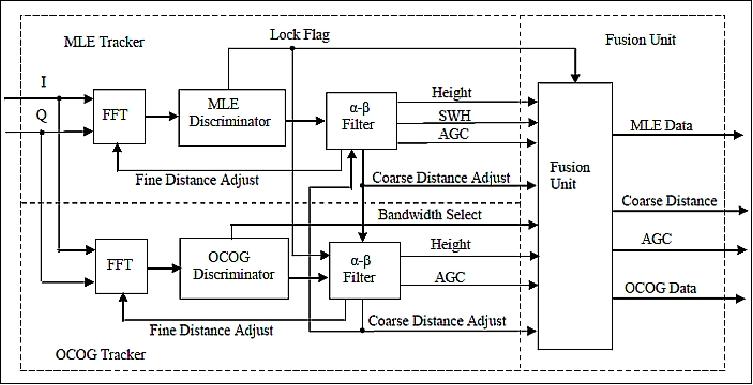
One of the goals of MCT is to measure both ocean and land without loss of tracking, so the MCT should have the ability to distinguish the different echoes from diverse surfaces and choose the different tracking strategies automatically. MCT is comprised of OCOG tracker, MLE tracker, and fusion unit.
Three bandwidths for chirp signal are adopted in MCT, and they are 320 MHz, 80 MHz and 20 MHz. The 320 MHz signal is arranged for ocean measurement, the 80 MHz is for the coastal zone, and the 20 MHz is for land or ice coverage. The echo signal from the coast or land is more dramatic than that from the ocean, so the OCOG discriminator can determine which bandwidth is the candidate at anyone time. The OCOG tracker also sends the selected bandwidth to the MLE discriminator.
The fusion unit receives all the results from the two trackers. MCT selects the MLE tracker's output as the current working parameters when MLE locks the target. Otherwise, when MLE loses locking, the OCOG tracker's output is chosen (Ref. 29).
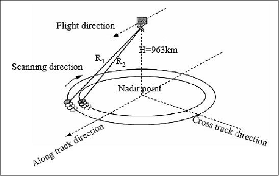
KU-RFSCAT (Ku-band Rotational Fan-beam Scatterometer) -referred to as SCAT
KU-RFSCAT is a Ku-band instrument designed and developed at NMRSL/CSSAR, Beijing. KU-RFSCAT is a pencil-beam conically scanning radar scatterometer. It uses a full-deramp pulse compression receiver with LFM (Linear Frequency Modulation) capability, which increases the number of the independent measurement samples to improve the measurement precision. A transmit signal generator signal generator creates a LF-chirp pulse with a bandwidth of 1~3 MHz in transmit mode; a separate receive mode reference signal generator creates a LF-chirp pulse with a bandwidth of 1~5 MHz as the de-ramp receiving reference. The separate design of the transmit signal generator and the reference signal generator allows the full range of onboard internal calibrations. 30) 31) 32)
The user requirements call for:
- Wind speed range: 2-24 m/s within an accuracy of 2 m/s or 10% of maximum value
- Wind direction accuracy: ±20º.
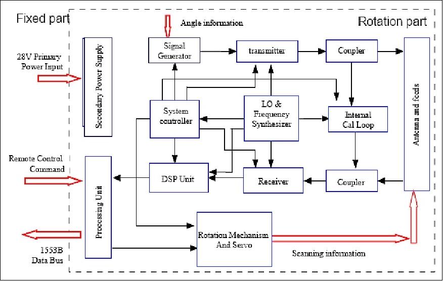
Instrument: The KU-RFSCAT instrument is comprised of the following elements:
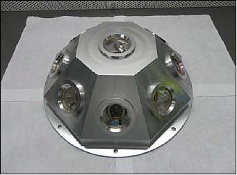
• Antenna and scanning servo unit: The antenna of KU-RFSCAT is a paraboloidal reflector antenna with a feed very slightly off-set. It features two off-nadir pointing beams for the two orthogonal polarizations.
• T/R frontend unit: This unit includes a high-isolation (> 130 dB) T/R switch matrix and an internal calibration loop. A very small portion of the output microwave RF power from the transmitter is being coupled to the internal calibration loop for output power and receiver gain floating calibration.
• Receiver RF-IF unit, including the low noise amplifier (LNA), the down-converting mixer, the IF filter and amplifier and the I-Q detector unit
• Transmitting signal unit: It generates the linear FM chirp signal for the transmitting mode.
• Reference signal unit: It generates the linear FM chirp signal as the reference for the deramp receiver. This signal uses the same FM slope as the transmitted chirp signal, but its duration is longer than the transmitted pulse to cover the range extending within the footprint of the antenna beam.
• RF power amplifier unit: It is a TWTA (Travelling Wave Tube Amplifier) to generate the required 100 W transmitting power.
• Frequency synthesizer unit
• DSP, system control and management unit: DSP includes the FFT (Fast Fourier Transform) operation for full-deramp receiving and the noncoherent resolution cell average.
• Secondary power supply unit.
Parameter | Value | Parameter | Value |
Center frequency | 13.256 GHz | Pulse width | 0.65~1.2 ms |
LF bandwidth | 3-6 MHz | Polarization | Outer beam: VV |
Backscattering range | -40~+20 dB | Backscattering precision | 0.5 dB |
Wind speed range (m/s) | 2~24 (after processing) | Wind speed precision | 2 m/s (after processing) |
Wind direction range | 0-360º | Wind direction precision | 20º |
Swath width | > 1400 km | PRF (Pulse Repetition Frequency) | 100~200 Hz |
Peak power | 110 W | Antenna size | 1.0 m diameter |
Ground resolution | 25 km | Antenna beamwidth | 1.02º (el) x 1.10º (az) |
Footprint size | Outer beam: 37 x 26 km | Local incidence angle | Outer beam: 49º |
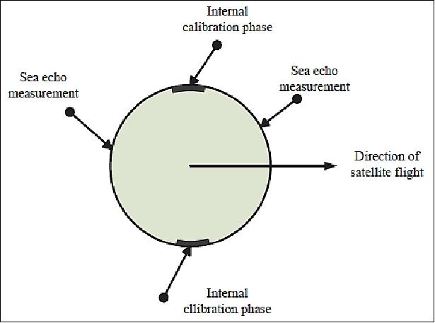
Instrument calibration: KU-RFSCAT employs an internal calibration loop. The fluctuations of the receiver gain and the transmitter output power can be calibrated by a internal calibration procedure when the antenna is rotated to the cross-track directions. 33)
The ratio method is employed in the internal calibration to eliminate the negative impacts caused by parameter fluctuation from receivers and transmitters during in-orbit operation. Internal calibration is carried out by coupling portion of the TWTA output-power to the receiver to form a closed loop. Figure 18 illustrates the timing sequences for observation and internal calibration during each rotation. Internal calibration is performance twice with each rotation cycle with an interval of 1.8s, at the edge of the swath.
An important problem in SCAT calibration is that only one pulse can be received by the transponder in a calibration routine, which is inadequate to acquire high accuracy calibration. To solve the problem without disturbing the operations of SCAT, an innovative scheme is employed: SIMO (Single-Input-Multiple-Output). After the transponder receives a pulse, a sequence of short (~100us) chirps is transmitted. Each chirp has the same chirp rate (bandwidth divided by the time duration) as the transmitter chirp of the SCAT, and each one is modulated by a different carrier so that they can be resolved in the range window of SCAT. - In the full de-ramp theory, once the two chirps have the same chirp rate, the signal after the mixer is a sinusoid. As a result, there are many echoes of one single transponder in the SCAT range window. Therefore more information of the SCAT antenna pattern can be exploited and a more accurate calibration is possible (Ref. 28).
DORIS (Determination Orbite Radiopositionnement Integres Satellite)
In 2008, CNES and CNSA reached an agreement to embark the DORIS instrument of CNES on the HY-2 spacecraft. 34) 35)
HY-2A is the first mission which will serve the French-Chinese cooperation in the space oceanography domain. The cooperation will consist in the provision of the satellite data by NSOAS (National Satellite Ocean Application Service) and for CNES in the provision of the POD (Precise Orbit Determination) based on data supplied by a DORIS instrument, a GPS and the LRA (Laser Ranging Assembly) measurements.. This precise orbit will be used by NSOAS to create altimetry products that will then be integrated by CNES to realise multi-mission products distributed by AVISO (Archivage Validation Interprétation des Données des Satellites Océanographiques). DORIS data will be made available through the IDS (International DORIS Service).
LRA (Laser Ranging Assembly)
References
1) Mingsen Lin, "The Contribution of Global Ocean Observation of Continuity of HY-2 Satellite," Nov. 7, 2008, URL: http://www.coastalt.eu/files/pisaworkshop08/pres/08-HY-2_satellite_contribution.pdf
2) Xiaolong Dong, Ke Xu, Heguang Liu, Jingshan Jiang, "The Radar Altimeter and Scatterometer of China's HY-2 Satellite," Proceedings of IGARSS 2004, Anchorage, AK, USA, Sept. 20-24, 2004
3) "State Oceanic Administration (SOA) and HY-2," URL: http://www.godae.org/~godae-data/IGST/SOA_and_HY-2.ppt
4) http://smsc.cnes.fr/HY-2A/GP_satellite.htm
5) "China successfully launches maritime satellite," Space Travel, Aug. 17, 2011, URL: http://www.space-travel.com/reports/China_successfully_launches_maritime_satellite_999.html
6) "HY-2A: successful launch," AVISO, Aug. 17, 2011, URL: http://www.aviso.oceanobs.com/en/news-storage/news-detail/index.html?tx_ttnews[cat]=21&tx_ttnews[tt_news]=1064&cHash=f2c64559b9
8) "Satellite: HY-2A," WMO OSCAR, Jan. 14, 2016, URL: http://www.wmo-sat.info/oscar/satellites/view/176
9) "Hurricane Patricia seen by altimeters," CNES, AVISO+, Oct. 27, 2015, URL: http://www.aviso.altimetry.fr/en/news/front-page-news/news-detail.html?tx_ttnews[tt_news]=1839&cHash=68a51e69d519a7a8c7ca7a45e65f438e
10) Mingsen Lin, Yongjun Jia, Youguang Zhang, "Global assessment of HY-2 satellite," Proceedings of the IGARSS (International Geoscience and Remote Sensing Symposium) 2015, Milan, Italy, July 26-31, 2015
11) A. Stoffelen, "NWP benefits by the HY-2A as part of the International Wind Scatterometer Constellation," Proceedings of the IGARSS (International Geoscience and Remote Sensing Symposium) 2015, Milan, Italy, July 26-31, 2015
12) Peng Zhang, Jun Gao, "Report from CNSA," 16th GSICS (Global Space-based Inter-Calibration System) Executive Panel, Boulder, CO, USA, 15-16 May 2015, URL: https://web.archive.org/web/20160406072516/http://www.wmo.int/pages/prog/sat/meetings/linkedfiles/GSICS-EP-16_Doc_09_CNSA-report.pptx
13) J. Lambin, "Ocean Surface Topography Virtual Constellation," SIT-30 Agenda Item #7b, 30th CEOS SIT Meeting, CNES Headquarters, Paris, France, 31st March – 1st April 2015, URL: http://ceos.org/document_management/Meetings/SIT/SIT-30/SIT-30_08_01_OST-VC_LambinJ.pptx
14) Lifeng Boa, Peng Gao, Hailong Peng, Yongjun Jia, C. K. Shum, Minseng Lin, Qi Guo, "First accuracy assessment of the HY-2A altimeter sea surface height observations: Cross-calibration results," Advances in Space Research, Volume 55, Issue 1, 1 January 2015, pp: 90–105, doi:10.1016/j.asr.2014.09.034
15) Yongjun Jia, Mingsen Lin, Youguang Zhang, "Current status of the HY-2A Satellite Radar Altimeter and its prospect," Proceedings of IGARSS (IEEE Geoscience and Remote Sensing Society) 2014, Québec, Canada, July 13-18, 2014
16) Juhong Zou, Xuetong Xie, Yi Zhang, Mingsen Lin, "Wind retrieval processing for HY-2A microwave scatterometer," Proceedings of IGARSS (IEEE Geoscience and Remote Sensing Society) 2014, Québec, Canada, July 13-18, 2014
17) C. Martin-Puig, B. Martinez-Val, J. Yang, " Cross-calibration of HY-2A with Jason-2 and CryoSat-2," Living Planet Symposium, Edinburgh, UK, Sept. 9-13, 2013
18) He Wang, Jianhua Zhu, Mingsen Lin, Xiaoqi Huang, Yili Zhao, Chuntao Chen, Youguang Zhang, Hailong Peng, "First sixmonths quality assessment of HY-2A SCAT wind products using in situmeasurements," Acta Oceanologica Sinica, 2013, Vol. 32, No. 11, pp: 27-33, DOI: 10.1007/s13131-013-0374-5
19) "HY-2A Microwave Scatterometer," SOA/NSOAS Technical and Scientific Workshop, Darmstadt, Germany, June 17-21, 2013
20) Xiaofeng Yang, Xiaofeng Li, Yang Yu, Ziwei Li, "Validation of sea surface wind vector retrieval from China's HY-2A Scatterometer," Proceedings of IGARSS (IEEE International Geoscience and Remote Sensing Symposium), Melbourne, Australia, July 21-26, 2013
21) Lifeng Bao, "Data Quality Estimation of HY-2A Altimeter," Proceedings of the Symposium '20 years of Progress in Radar Altimetry', Venice, Italy, Sept. 24-29, 2012, (ESA SP-710, Feb. 2013)
22) J-F. Legeais, M. Ablain, Y. Faugère, M. Dejus, T. Guinle, S. Mazeau, N. Picot, J. Lachiver, Pr Lin Mingsen, Zhang Youguang, Peng Hailong, "HY-2A and DUACS (Data Unification and Altimeter Combination System) altimeter products," OSTST 2012 (Ocean Surface Topography Science Team) meeting, Venice, Italy, Sept. 22-29, 2012, URL: http://www.aviso.oceanobs.com/fileadmin/documents/OSTST/2012/oral/01_thursday_27
/05_regional_and_global_calval_II/09_CV2_Legeais2.pdf
23) "SOA gains control of China's oceanic surveying satellite," Space Daily, March 6, 2012, URL: http://www.spacedaily.com/reports/SOA_gains_control_of_Chinas_oceanic_surveying_satellite_999.html
24) S. P. Mertikas, A. Daskalakis, X. Zhou, I. N. Tziavos, G. Vergos, O. Andersen, V. Zervakis, Y. Q. Chen, "Latest results for the Jason-2 bias & preparations for the HY-2 Cal/Val using Gavdos," Symposium '20 years of Progress in Radar Altimetry', Venice, Italy, Sept. 24-29, 2012, URL: http://www.aviso.oceanobs.com/fileadmin/documents/OSTST/2012/oral/01_thursday_27
/02_regional_and_global_calval_I/04_CV1_Mertikas.pdf
25) http://www.aviso.oceanobs.com/en/news-storage/news-detail/index.html?tx_ttnews[cat]=21&tx_ttnews[tt_news]=1068&tx_ttnews[backPid]=322&cHash=f87aca98ef
26) P. Delu, "Future-generation satellites of Chinese ocean remote sensing," Proceedings of the SPIE, Vol. 5570, 2004, pp. 228-232,.`Sensors, Systems, and Next-Generation Satellites VIII', Edited by Meynart, Roland; Neeck, Steven P.; Shimoda, Haruhisa, Maspalomas, Gran Canaria, Spain, Sept. 13, 2004, DOI: 10.1117/12.563894
27) Xiaolong. Dong, Ke Xu, Heguang Liu, Jingshan Jiang, "The Radar Altimeter and Scatterometer of China's HY-2 Satellite," Proceedings of IGARSS 2004, Anchorage, AK, USA, Sept. 20-24, 2004
28) Xu Xi-Yu, Guo Wei, Liu He-Guang, Shi Ling-Wei, Lin Wen-Ming, Du Yue-Heng, "Design of the Interface of a Calibration Transponder and an Altimeter / Scatterometer," Proceedings of IGARSS (International Geoscience and Remote Sensing Symposium), Vancouver, Canada, July 24-29, 2011
29) Ke Xu, Jingshan Jiang, Heguang Liu, "HY-2A Radar Altimeter Design and in-flight preliminary results," Proceedings of IGARSS (IEEE International Geoscience and Remote Sensing Symposium), Melbourne, Australia, July 21-26, 2013
30) Xiaolong Dong, Shuyan Lang, Tao Wang, Heguang Liu, "Accuracy and Resolution Analysis of the Pencil Beam Radar Scatterometer Onboard China's HY-2 Satellite," Proceedings of IGARSS 2007 (International Geoscience and Remote Sensing Symposium), Barcelona, Spain, July 23-27, 2007
31) Xiaolong Dong, Wemming Lin, "System design and performance simulation of a spaceborne Ku-band rotation fan-beam scatterometer," Proceedings of IGARSS 2008 (IEEE International Geoscience & Remote Sensing Symposium), Boston, MA, USA, July 6-11, 2008
32) Xiaolong Dong, Wemming Lin, Shuyan Lang, Heguang Liu, Jingshan Jiang, "Compromise and trade-off between signal-to-noise ratio and number of independent samples for radar scatterometers with pulse compression," Proceedings of IGARSS 2008 (IEEE International Geoscience & Remote Sensing Symposium), Boston, MA, USA, July 6-11, 2008
33) Xiaoning Wang, Lixia Liu, Haoqiang Shi, Xiaolong Dong, Di Zhu, "In-Orbit Calibration and Performance Evaluation of HY-2 Scatterometer," Proceedings of IGARSS (International Geoscience and Remote Sensing Symposium), Munich, Germany, July 22-27, 2012
34) P. Ferrage, G. Tavernier, A. Auriol, "DORIS system status and future missions," IDS (International DORIS Service) Workshop, Nice, France, Nov. 12-14, 2008, URL: http://ids.cls.fr/documents/report/ids_workshop_2008/IDS08_s1_Ferrage_DORISMissions.pdf
35) http://smsc.cnes.fr/DORIS/
36) http://ilrs.gsfc.nasa.gov/docs/HY2_retroreflector.pdf
The information compiled and edited in this article was provided by Herbert J. Kramer from his documentation of: "Observation of the Earth and Its Environment: Survey of Missions and Sensors" (Springer Verlag) as well as many other sources after the publication of the 4th edition in 2002. - Comments and corrections to this article are always welcome for further updates (eoportal@symbios.space).
Overview Spacecraft Launch Mission Status Sensor Complement References Back to top