SARAL (Satellite with ARgos and ALtiKa)
EO
Atmosphere
Ocean
CNES
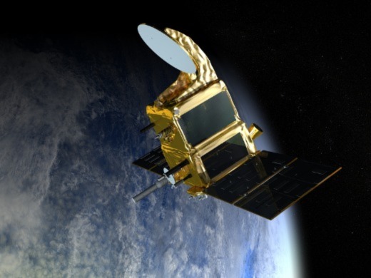
SARAL is an altimetric minisatellite operated by ISRO and CNES. Launched in 2013, data gathered by SARAL has applications in oceanography and atmospheric studies.
Quick facts
Overview
| Mission type | EO |
| Agency | CNES, ISRO |
| Mission status | Operational (extended) |
| Launch date | 25 Feb 2013 |
| Measurement domain | Atmosphere, Ocean |
| Measurement category | Atmospheric Humidity Fields, Ocean topography/currents, Ocean surface winds, Ocean wave height and spectrum |
| Measurement detailed | Atmospheric specific humidity (column/profile), Wind speed over sea surface (horizontal), Significant wave height, Sea level |
| Instruments | A-DCS3, AltiKa, DGXX |
| Instrument type | Precision orbit, Data collection, Radar altimeters |
| CEOS EO Handbook | See SARAL (Satellite with ARgos and ALtiKa) summary |
Summary
Mission Capabilities
The primary instrument of SARAL is AltiKa (Altimeter in Ka band), the first radar altimeter operating at a frequency of 35.75 GHz. The high-resolution altimeter has a dual-frequency radiometric function which allows the altimetry measurements to be corrected for the effects of the signal passing through the troposphere. AltiKa is coupled with the DORIS (Doppler Orbitography and Radiopositioning Integrated by Satellite) tracking system and an LRA (Laser Retroreflector Array) for the measurement of precision orbits. Argos-3 (also known as A-DCS3) is the data collection system of SARAL, which collects location data by Doppler measurements from remote terminals in the ground segment.
SARAL has altimetric applications in oceanography, cryospheric sciences, hydrology and geodesy.
Performance Specifications
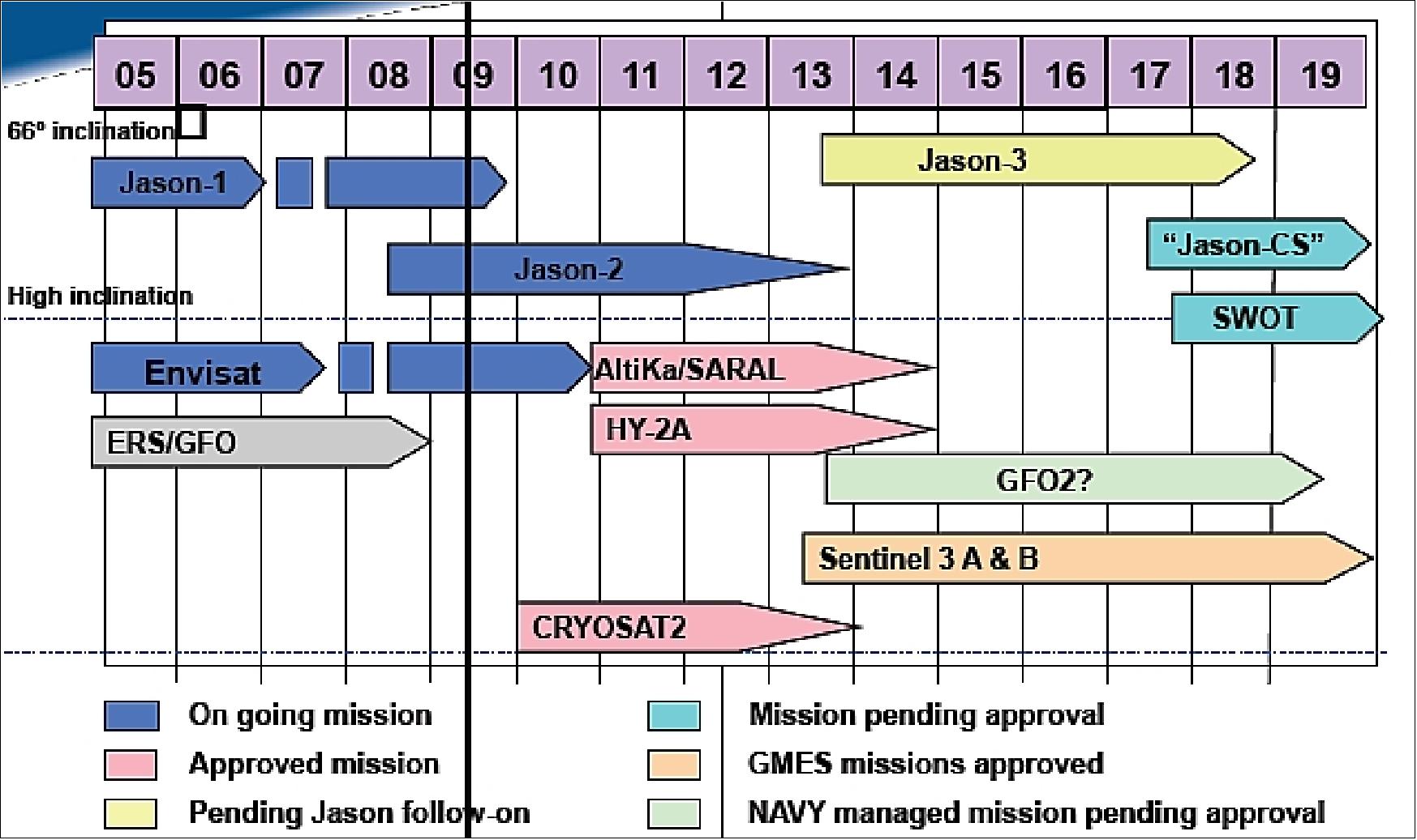
AltiKa provides a spatial resolution of 40-50 km for SSH (Sea Surface Height) investigations. This improves upon similar altimetry missions such as Jason and Envisat, which have a spatial resolution of 70 - 80 km. SARAL is a complementary mission to Jason-2 (by NASA and CNES) and follows on from Envisat (by ESA), which ended its mission in 2012.
SARAL operates in a sun-synchronous LEO (Low Earth Orbit) at an altitude of approximately 800 km, inclined at 98.538°. The satellite initially had a 35-day repeat cycle, but an issue with its reaction wheels in 2015 forced it into a drifting phase. SARAL’s initial orbit was identical to that of Envisat, allowing for data continuity of altimetry measurements in the long term. Over the ocean, SARAL has a data coverage of greater than 99.5%.
Space and Hardware Components
The minisatellite is based on the ISRO IMS-2 (Indian Minisatellite-2) bus, which has an aluminium honeycomb sandwich structure and a launch mass of 450kg. The bus has all general platform subsystems with complete redundancy, including three-axis stabilisation and reaction wheels providing actuation. The SARAL payload data is transmitted in X-band at 32 Mbit/s.
In March 2015, technical issues were encountered with the reaction wheels which led to the decision of relaxing the orbit. After July 2016, SARAL left its repetitive orbit by beginning the SARAL-DP (Drifting Phase). This resulted in a drift between successive ground tracks, however, data processing, latency and the altimeter function remain nominal. The repeat cycle of 35 days is no longer kept but the orbit preserves subcycles of between 15 and 17 days.
SARAL (Satellite with ARgos and ALtiKa)
Spacecraft Launch Mission Status Sensor Complement Ground Segment References
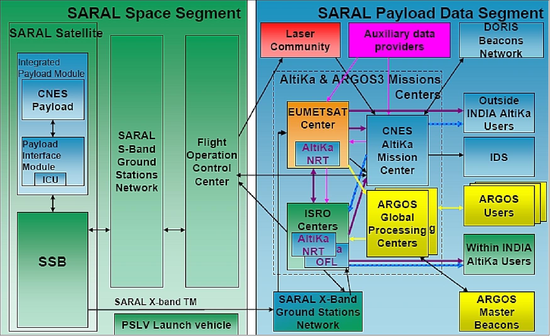
SARAL is a cooperative altimetry technology mission of ISRO (Indian Space Research Organization) and CNES (Space Agency of France). In this setup, CNES is providing the payload module consisting of the AltiKa altimeter, DORIS, LRA, and Argos-3 DCS (Data Collection System), and the payload data reception and processing functions, while ISRO is responsible for the platform, launch, and operations of the spacecraft. A CNES/ISRO MOU (Memorandum of Understanding) on the SARAL mission was signed on Feb. 23, 2007.
The overall objectives are to realize precise, repetitive global measurements of sea surface height, significant wave heights and wind speed for: 1) 2) 3)
• The development of operational oceanography (study of mesoscale ocean viability, coastal region observations, inland waters, marine ecosystems, etc.)
• Understanding of climate and developing forecasting capabilities
• Operational meteorology.
The SARAL mission is considered to be complementary to the Jason-2 mission of NASA/NOAA and CNES/EUMETSAT. The combination of two altimetry missions in orbit has a considerable impact on the reconstruction of SSH (Sea Surface Height), reducing the mean mapping error by a factor of 4. 4) 5) 6)
AltiKa, the altimeter and prime payload of the SARAL mission, will be the first spaceborne altimeter to operate at Ka-band. Based on a wideband Ka-band altimeter (35.75 GHz, ~500 MHz) concept, AltiKa was initially proposed in 2002 as a CNES altimetry minisatellite mission (150 kg) on the Myriade platform. Feasibility studies were also made to accommodate AltiKa on the TopSat platform of SSTL (Surrey Satellite Technology Ltd.). In Dec. 2005, CNES approved the development of the AltiKa payload since an opportunity arose to embark the instrument on a cooperative mission of ISRO and CNES, namely OceanSat-3. However, early in 2006, the OceanSat-3 launch was postponed to the period 2011/12, beyond the schedule objective of AltiKa. As a consequence, CNES and ISRO established an alternative option, based on a dedicated minisatellite using a new SSB (Small Satellite Bus) platform to be developed as ISRO. 7) 8) 9) 10)
ISRO responsibilities | CNES responsibilities |
Project Management, shared with CNES | Project Management, shared with ISRO |
SARAL satellite engineering | Overall SARAL system engineering |
Small Satellite Bus/Indian Mini Satellite - 2 Platform | Integrated Payload Module including: |
SARAL Satellite Integration and Tests | Support for SARAL Payload Module Integration and Tests |
PSLV Launch vehicle and services |
|
Ground System & Operations | • 2 Polar X-band stations [Swedish Space Corp.] |
User services | User services |
| ALTIKA System Coordination with other altimetry missions; expertise and long term CALVAL |
Spacecraft bus and payload module development
The minisatellite, as provided by ISRO, involves nothing less than the development of a new spacecraft bus.
The general spacecraft architecture consists of two modules:
- the introduction of a new modular bus (under development at ISRO as of 2007), referred to as SSB (Small Satellite Bus),
- and PIM (Payload Instrument Module).
Two SSB designs are under development: 12) 13)
1) The first one is being developed for a minisatellite series with a total launch mass of about 450 kg, including a payload mass of ~ 200 kg.
2) The second one is considered for a microsatellite series with a total launch mass of around 100 kg, including a payload mass of 20-30 kg
In 2012, ISRO refers to the former SSB as the IMS-2 (Indian MiniSatellite-2) bus. The IMS-2 bus evolved as an operational minisatellite class platform with complete redundancy in the mainframe subsystems. The IMS-2 development is an important milestone, it is envisaged at ISRO/ISAC to be a workhorse for different types of applications / operational future missions. The first mission of the IMS-2 implementation is SARAL. 14)
The design layout is such that the bus module and the payload module of each series may be integrated and tested separately (thus reducing the interdependency during the realization between both modules). IMS-2 is also designed to accommodate different types of payloads with minor modifications from mission to mission. IMS-2 is developed with the intention to permit a multiple payload launch by PSLV using the DLA (Dual Launch Adaptor), which caters to minisatellites in the class of 450-600 kg.
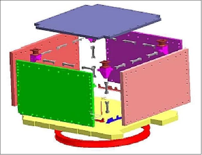
The structure of the bus is built with aluminium honeycomb panels. It consists of 3 horizontal decks, namely the bottom deck, top deck and payload deck, and four vertical equipment panels. The bottom deck has the interface ring (with Merman band interface 937VB) bolted to it. The design employs a number of stiffness measures to avoid any resonant frequencies of the launcher in both lateral and longitudinal directions.
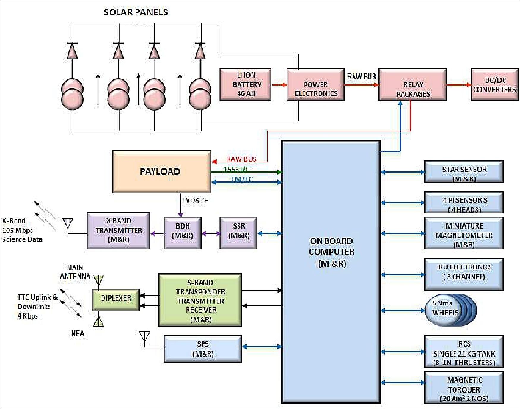
The IMS-2 system design includes all general platform services functions such as the EPS (Electric Power Subsystem) with battery and solar arrays, the AOCS (Attitude and Orbit Control Subsystem), TT&C (Telemetry, Tracking & Command) subsystem, RCS (Reaction Control Subsystem), the thermal subsystem for bus (a passive system is used), and mechanisms (for solar panel deployment), etc. Most of the systems have redundancy/large margins or space capacity.
System | Item | Value |
Orbit | LEO, sun-synchronous | Mission specific |
Mission | - Design life | 5 years |
Mechanical | - Structural configuration | Aluminium honey comb sandwich structure with 4 vertical panels and 2 horizontal decks |
Power | - Solar array power @ EOL | 850 W |
AOCS (Attitude and Orbit Control Subsystem) | - Attitude control | 3-axis stabilized with reaction wheels / RCS system |
RF communications | - TC uplink communications | Hot redundant S-band receivers, 4 kbit/s |
Payload-mechanical | - Payload mass | 200 kg max |
Payload-electrical | - Payload data storage capacity | 64 Gbit storage (max) |
Miscellaneous | - Launch vehicle interface | PSLV – DLA compatible |
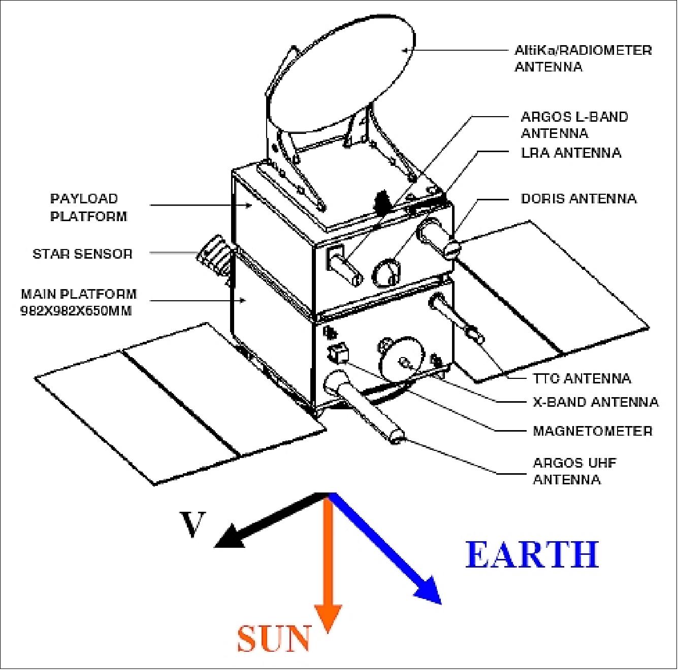
The minisatellite bus module has a standard simple interface for the payload module. The new bus derives its shape from previous IRS configurations with a cuboid structure. The bottom deck of the minisatellite bus is measuring 900 mm x 900 mm providing an interface with the launch vehicle. The launcher interface uses a Merman clamp band, 937VB. The top deck is of the same size as the bottom deck featuring four corner points extending as pillars to provide a four-point interface for the payload module.
The PIM (Payload Instrument Module) consists of a set of CFRP (Carbon Fiber Reinforced Plastic) based panels with appropriate interfaces for mounting onto the main platform and for mounting the payloads and associated elements. The payload-related systems like data handling, SSR (Solid State Recorder), etc., are mission-specific functions.
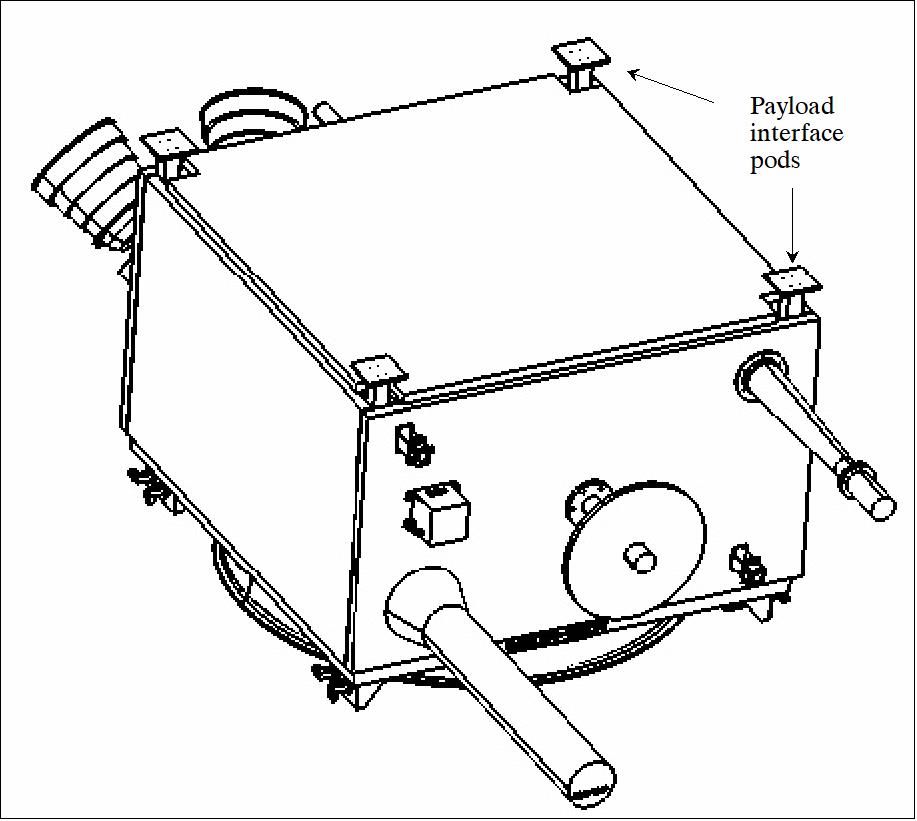
The PIM is also of square shape and of the same cross-section size as that of the bus with four corners (payload interface pods) interfacing with the main bus. The PIM, unlike the bus module, has the freedom to grow vertically; the only limitation is the available volume within the heat shield enclosure of the launch vehicle and allowable frequency constraints. 15)
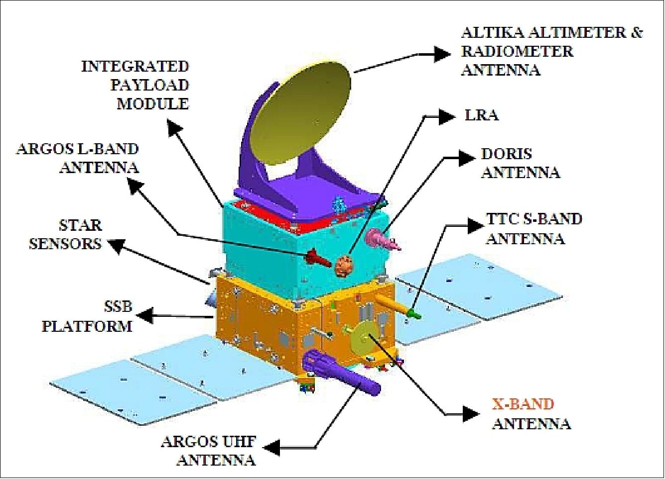
Spacecraft
The structural configuration of the IMS-2 bus is a cuboid of size: ~1m x 1 m x 0.6 m. Use of an aluminium honeycomb sandwich construction. The face sheet is aluminium and the core consists of an aluminium honeycomb structure. The structure consists of two horizontal decks, namely a bottom deck and a top deck, and four vertical decks, EP01 to EP04.
AOCS: The spacecraft is 3-axis stabilized. Attitude is sensed by a miniature star sensor providing an attitude knowledge of < 30 µarcsec about all axes. This attitude information is also used to update the inertial angle information of the gyros. The gyros are also a miniaturized version. Further attitude sensors are 4 sun sensors (4π FOV) and a miniature 3-axis magnetometer.
- Actuation is provided by 4 reaction wheels (5 Nms) arranged in tetrahedral configuration, and 2 magnetorquers. The latter one is used for the momentum dumping of the wheels. The monopropellant RCS (Reaction Control Subsystem) uses a single tank (21 kg of propellant) with two blocks of 1N thrusters. It is mainly used for orbit maintenance.
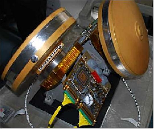
The star sensor is a single integrated sensor package consisting of a detector, preamplifier and an FPGA, which acts as an intelligent video processor. An IRU (Inertial Reference Unit) is used for attitude referencing in all phases of spacecraft operations. The IRU consists of a cluster assembly where three numbers of two-degree-of-freedom MDTG (Multiplexed Digital Trunk Group) are mounted on a cluster and suspended with 4 space-qualified vibration isolators separately.
- Pointing accuracy = 0.1º (3σ)
- Drift rate: ± 10-4 º/s (3σ)
EPS: The EPS employs a single bus, a DET (Direct Energy Transfer) system, with an unregulated bus voltage of 28-33 V. An average power of ~500 W is provided with 2 articulated solar panels (total area of 3.88 m2) with UTJ solar cells. Maximum power of 850 W. The power output of the solar array is regulated by the battery charge conditions. A Li-ion battery with 46 Ah capacity is used for eclipse phase operations. The power conditioning and the power distributing converters have full redundancy.
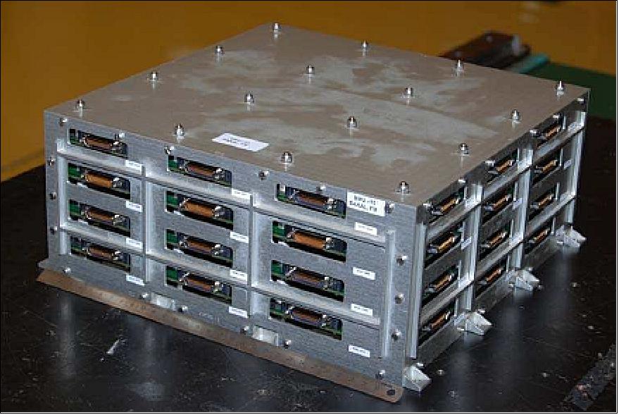
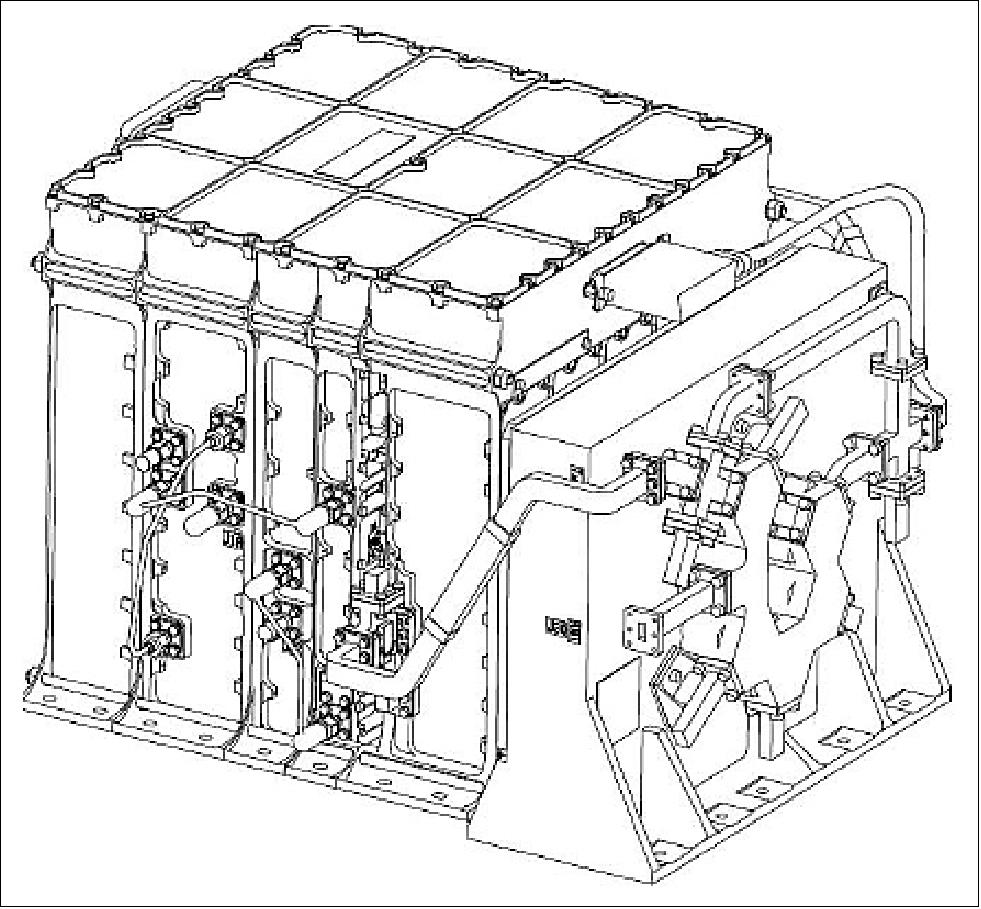
The BMU (Bus Management Unit) with the OBC (OnBoard Computer) take care of all data handling functions using the MIL‐STD‐1553B standard interface with all onboard subsystems. The payload data handling subsystem employs serial interfaces to the baseband data handling formatter. The formatter receives the payload data packets, annotates these with the housekeeping data, and deposits them onto the SSR. All the hardware required for BMU is optimized and implemented using four cards of size 31 cm x 31 cm. The CPU is built around the MAR31750 processor, with the MMU MAR31751 device for memory expansion. Figure 8 shows the BMU/OBC hardware.
RF communications: There is no real-time data transmission requirement for SARAL. The SSR has a capacity of 32 Gbit. The TT&C data are transmitted via S-band. The TC uplink modulation scheme is FM/PSK/PCM and the uplink data rate is 4 kbit/s. The TM data is BPSK modulated, and the transmit power is 1 W. A near omnidirectional TT&C antenna is used.
The payload data handling system consists of BDH (Baseband Data Handling) system and the SSR (Solid State Recorder). The data handling system collects, formats, and stores all data for later downlink. All links, both up and down, are encrypted to prevent unauthorized access to the data. It interfaces with the payloads and acquires the data from payloads through the LVDS interface. The read payload data will be formatted as per CCSDS Transfer Frame format. The playback data is RS (Reed Solomon) coded, randomized, convolution coded and given to the X-band system for transmission to the ground. The SSR memory capacity is variable and is based on the mission requirements. The maximum capacity of SSR is 64 Gbit.
The SARAL payload data are transmitted in X-band at data rates of 32 Mbit/s. The transmitter uses an SSPA (Solid State Power Amplifier) with an EIRP output of ~4 W. A shaped beam antenna with a gain of +4.5 dBi at ±65° along with 4W SSPA provides the necessary link margin.
In addition, the UHF link is used to collect the data from the ground segment with the Argos-3 onboard instrument while the L-band is used to transmit the collected data to the data centers.
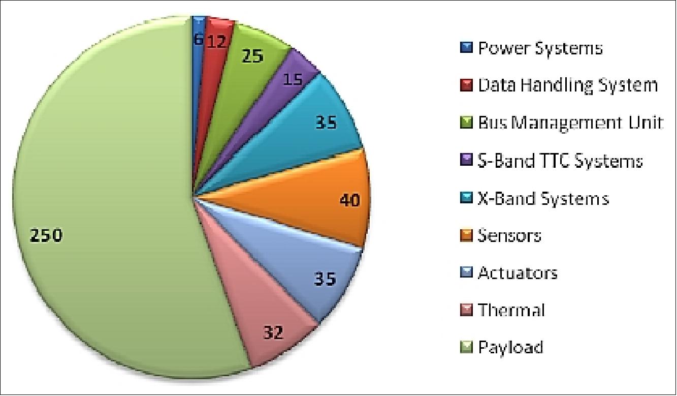
The SARAL spacecraft has a mass budget of about 407 kg. The IMS-2 has a total mass of 199 kg, while the total payload mass is 147 kg (with 5% margin). The design life is 5 years.
Launch
The SARAL minisatellite was launched on February 25, 2013, from SDSC-SHAR (Sriharikota, India) on the PSLV-C20 launcher of ISRO. 16)
Orbit: Sun-synchronous near-circular dawn-dusk orbit, altitude of ~800 km, the inclination of 98.538º, orbital period of 100.6 minutes, LTAN (Local Time on Ascending Node) = 6:00 hours, repeat cycle = 35 days (No of orbits within a cycle = 501).
The six secondary payloads manifested on this flight were:
• BRITE-Austria (CanX-3b) and UniBRITE (CanX-3a), both of Austria. UniBRITE and BRITE-Austria are part of the BRITE Constellation, short for "BRIght-star Target Explorer Constellation", a group of 6.5 kg, 20 cm x 20 cm x 20 cm nanosatellites whose purpose is to photometrically measure low-level oscillations and temperature variations in the sky's 286 stars brighter than visual magnitude 3.5.
• Sapphire (Space Surveillance Mission of Canada), a minisatellite with a mass of 148 kg.
• NEOSSat (Near-Earth Object Surveillance Satellite), a microsatellite of Canada with a mass of ~74 kg.
• AAUSat3 (Aalborg University CubeSat-3), a student-developed nanosatellite (1U CubeSat) of AAU, Aalborg, Denmark. The project is sponsored by DaMSA (Danish Maritime Safety Organization).
• STRaND-1 (Surrey Training, Research and Nanosatellite Demonstrator), a 3U CubeSat (nanosatellite) of SSTL (Surrey Satellite Technology Limited) and the USSC (University of Surrey Space Centre), Guildford, UK. STRaND-1 has a mass of ~ 4.3 kg.
The University of Toronto arranged for the launch to carry three small satellites for universities as part of its Nanosatellite Launch Services program, designated NLS-8: BRITE-Austria, UniBRITE and AAUSat3. The three NLS satellites used the XPOD (Experimental Push Out Deployer) separation mechanism of UTIAS/SFL for deployment.
SARAL-AltiKa is intended as a gap filler mission between the RA-2 onboard Envisat (ESA, launched in 2002, and lost in 2012) and the SRAL onboard Copernicus/Sentinel-3 (to be launched in 2014). As such, SARAL-AltiKa will fly on the same orbit as Envisat of ESA (allowing to re-use of the mean sea surface fields in the data processing and having sea level anomaly monitoring with high quality from the start of the mission), to ensure a continuity of altimetry observations in the long term. On the other hand, the local time of passage over the equator will be different due to specific cover requirements for the instruments constellation of the Argos system.
Mission Status
• February 25, 2025: SARAL celebrates twelve years in orbit. The quality of its products still satisfies the mission requirements. 46)
• December 19, 2023: To celebrate ten years since SARAL's launch, AVISO has released a special newsletter edition dedicated to the satellite's accomplishments throughout the past decade. Following the reaction wheel anomaly in 2016, SARAL/AltiKa has continued operations in a drifting orbit phase, with the altimeter functioning nominally. Despite the loss of repeat ground tracks, data coverage has remained above 99.5 % over the ocean, and measurements of sea surface height (SSH) continue to meet the original accuracy requirements. The Ka-band altimeter has provided finer spatial resolution than earlier Ku-band systems, enabling improved observation of mesoscale ocean variability, coastal processes, and inland water bodies. 45)
- The mission has also contributed to hydrology and cryosphere studies by exploiting the limited penetration depth of Ka-band in snow and ice, and to geodetic applications through detection of small-scale gravity anomalies and seamounts. SARAL/AltiKa products have been routinely assimilated into operational wave forecasting models, supporting applications in oceanography and meteorology. The 10-year mission review highlights that the data remain valuable for both research and operational use, and continue to serve as a reference for future Ka-band altimetry missions.
• February 3, 2020: Since a reaction wheel failure in 2016, the SARAL satellite has been operating in a drifting orbit, which, while unplanned, has yielded useful data for geodesy and hydrology. SARAL/AltiKa’s findings, particularly on Ka-band performance, are informing the preparation of ESA’s upcoming CRISTAL mission, which will combine Ku- and Ka-band altimetry to improve snow depth measurements and polar monitoring, with SARAL serving as a key reference for validating Ka/Ku comparisons alongside CryoVex aircraft radars, ICESat-2 lidar, and in situ data. 17)
• February 2018: The SARAL/AltiKa mission has continued to operate despite reaction wheel issues in 2015 that led to the transition into a Drifting Phase (SARAL-DP) from July 2016. While the satellite no longer maintains a 35-day repeat cycle, it preserves subcycles of 15–17 days, relevant for mesoscale ocean observations. Importantly, the shift to drifting orbit has not affected the nominal functioning of the altimeter or the quality and latency of data, with coverage over the ocean exceeding 99.5%. SARAL/AltiKa has consistently met or surpassed its mission requirements, achieving a Sea Surface Height (SSH) RMS accuracy of 3.4 cm—better than the 4 cm requirement—and often outperforming reference Ku-band missions such as Jason-2. Its high-resolution Ka-band altimeter provides superior along-track sampling, reduced noise, and improved mesoscale signal detection, making it highly valuable for oceanographic applications. 18) 19)
- Beyond the open ocean, SARAL/AltiKa has demonstrated significant advances in coastal monitoring, inland water level measurements, ice studies, and geodesy. Its smaller footprint and higher pulse repetition frequency enable reliable measurements in smaller rivers and lakes, while reduced radar penetration in snow enhances ice monitoring and snow depth estimation. In geodesy, the Drifting Phase offers opportunities for mapping uncharted seamounts and resolving short-wavelength geoid anomalies. Overall, SARAL/AltiKa has validated the Ka-band’s advantages—including finer spatial and vertical resolution, negligible ionospheric effects, and improved signal-to-noise ratio—while showing minimal sensitivity to rain. As the first oceanographic altimeter operating solely at Ka-band, SARAL/AltiKa is considered a prototype for future missions, paving the way for advanced altimetric projects such as SWOT and CRISTAL, and reinforcing its role as a key member of the global altimetry constellation.
• July 1, 2016: From July 4, 2016, SARAL enters a new phase called SARAL-DP (Drifting Phase). Its altitude of 800 km is increased by 1 km and no more maneuvers are performed on the satellite, except for collision avoidance. This phase has a cycle numbering beginning at 100 and pass 1 starts at the first South Pole crossing after the altitude increase maneuver. 20)
• February 25, 2016: The joint CNES/ISRO SARAL mission has been on orbit for 3 years. 21)
• February 2015: The SARAL spacecraft is fully operational, under the control of the ISRO team. The ARGOS and AltiKa payloads are fully operational. The ARGOS service has good availability, with its altimetry products providing measurements on ice sheets, rivers and lakes, which is new with respect to previous CNES altimetry satellites such as Jason-2/3. AltiKa data are routinely distributed worldwide and contribute largely to the CMEMS (Copernicus Marine Service). 22)
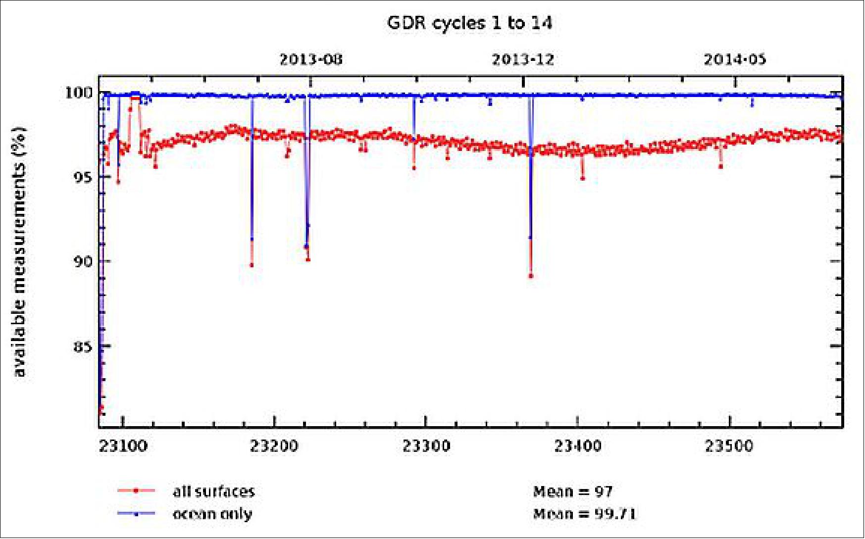
• November 2014: The SARAL/AltiKa mission currently distributes V2 products, operational since January 2014, with V3 planned for early 2015. Product validation highlights the mission’s strong performance, particularly in terms of data coverage over the ocean. As shown in Figure 11, SARAL/AltiKa achieves more than 99.5% coverage, with very few missing measurements relative to the reference ground track, thereby exceeding mission requirements. Designed as a gap-filler between Envisat’s RA-2 (lost in 2012) and Sentinel-3’s SRAL (launched in 2015), SARAL/AltiKa operates in the same orbit as Envisat, enabling continuity in sea level anomaly monitoring and re-use of mean surface fields for high-quality oceanographic data from the outset of the mission. 23)
• October 27, 2014: The SARAL/AltiKa Workshop was held in Konstanz, Germany to review the calibration/validation studies of the first SARAL data and the scientific investigations of data from the Franco-Indian satellite 20 months after its launch on 25 February 2013. The workshop highlighted the new altimetry capabilities of the Ka-band in areas such as oceanography (improved resolution in the open ocean, coastal altimetry), hydrology and the cryosphere.
• February 2014: The SARAL spacecraft and its payload are operating nominally. 24)
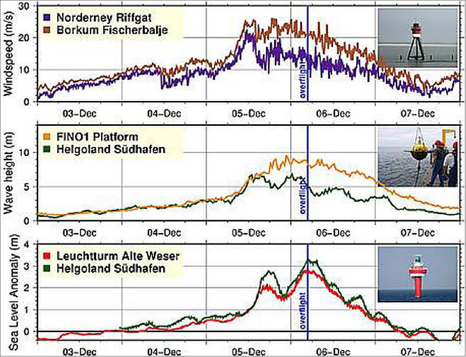
• December 6, 2013: During Cyclone Xaver, SARAL/AltiKa captured the storm’s impact across the North Sea, detecting storm surges up to 3 m above normal tide levels along the German coast and extending effects as far as 400 km offshore. The altimeter measured sustained wind speeds of around 20 m/s, consistent with in situ anemometer data, and recorded wave heights from 6 m near the coast to 12 m further offshore, in good agreement with buoy observations. These altimeter-derived sea level, wave height, and wind speed products were compared with in situ measurements and forecasts from the BSH circulation model and the JRC storm surge model, underscoring SARAL/AltiKa’s role in storm monitoring. 25)
• September 2013: Since July 2013, SARAL/AltiKa has been routinely providing geophysical data products, with OGDR and IGDR distributed from June 25, 2013, GDR available to PIs from August 2, and full GDR dissemination via the AVISO server from September. While some processing algorithms, such as those for radiometer neural network calibration, Sea State Bias, wind speed, and ICE2 retracking, still require tuning, the data have been well received by users. Presentations highlighted the ease of use and reliability of the products, with their accuracy, latency, and availability enabling SARAL/AltiKa data to be operationally integrated into multiple forecasting systems. 26)
• July 11, 2013: EUMETSAT contributes, as a partner in the SARAL mission, by adding the near real-time product service capability. 27) 28)
• April 1, 2013: The final orbit of the SARAL spacecraft was reached on March 13, 2013. Cycle No 1 was started on March 14, 2013. The AltiKa verification phase has begun with cycle 1, that is to say, since the well-functioning satellite reached its final orbit and crossed the equator at the predefine longitude of the first ascending node. After a quick validation performed by the mission project, the Near Real Time products (OGDR and IGDR) have been delivered in the "T" version (for testing) to the SARAL/AltiKa PIs from, respectively, 21st and 28th March 2013. 30)
• March 8, 2013: The subsystems of the SARAL platform were switched on between February 25 and 26, 2013. All the instruments are nominal. The first days of instrument commissioning indicate good performances, as expected. 31)
Sensor Complement
AltiKa (Altimeter in Ka-band)
The AltiKa project of CNES is based on a wideband Ka-band altimeter (35.75 GHz, 500 MHz), which will be the first oceanography altimeter to operate at such a high frequency. The high-resolution AltiKa altimeter has a dual-frequency radiometric function which allows the altimetry measurements to be corrected for the effects due to the signal passing through the wet troposphere. This is coupled with the DORIS (Doppler Orbitography and Radiopositioning Integrated by Satellite) tracking system and an LRA (Laser Retroreflector Array) for the measurement of precision orbits. 32) 33) 34) 35) 36) 37) 38)
The key feature of the altimeter payload has been the selection of Ka-band (35.75 GHz) for the altimeter avoids the need for a second frequency (necessary when using the Ku-band) to correct the ionospheric delay; the configuration allows the same antenna to be shared by the altimeter and the radiometer. This single antenna solves the accommodation problem of a conventional altimetry payload on a minisatellite (150 kg class). The Ka-band concept allows also the improvement of the range measurement accuracy by a factor of 3:1 due to the use of a wider bandwidth and a better pulse-to-pulse echo decorrelation.
The AltiKa design and development is a partnership of CNES, scientific laboratories (LEGI/CNRS, IFREMER, CLS, etc.) and industry, with TAS-F (Thales Alenia Space-France) as the prime instrument contractor. The AltiKa instrumentation consists of an integrated altimeter/radiometer instrument.
It is composed of the following elements:
• ORA (Offset Reflector Antenna) shared by the altimeter and the radiometer functions
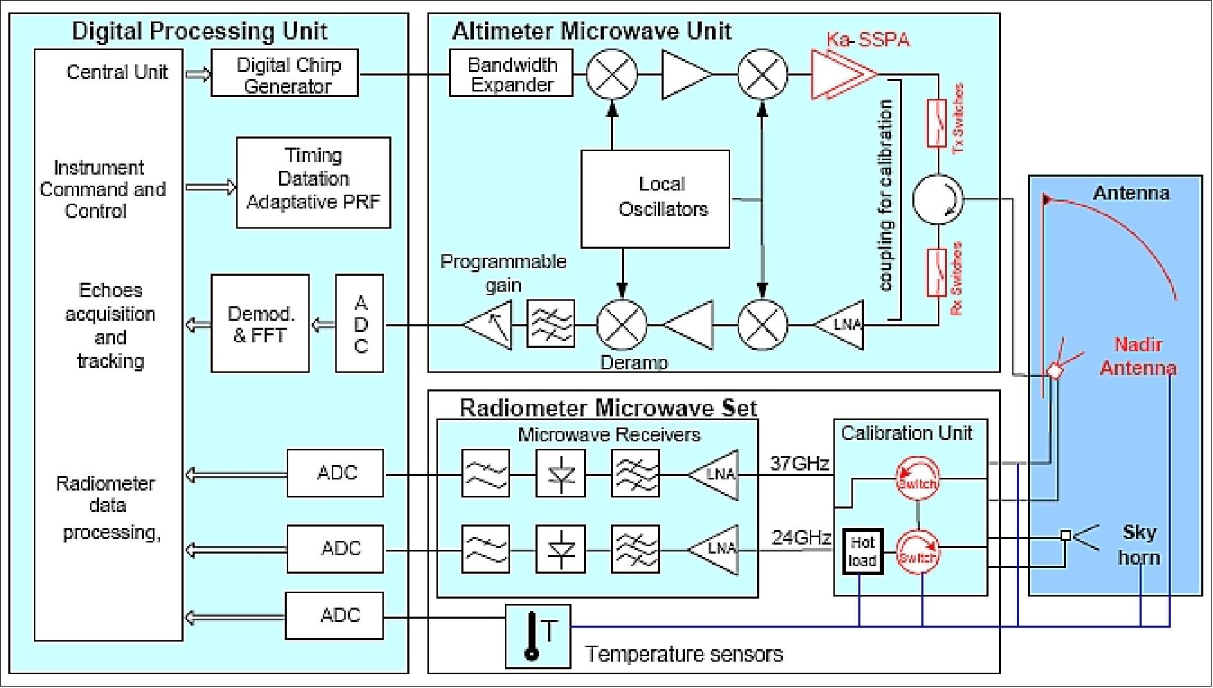
• AMU (Altimeter Microwave Unit). The objective is to gather all analogue support tasks of the altimeter operations (bandwidth expansion, frequency translations, local oscillator generation, high power amplification, transmitter/receiver/antenna duplexing, low noise amplification, deramp processing, bandwidth filtering, IF processing).
• RMU (Radiometer Microwave Unit). The objective is to gather all analogue support tasks of the radiometer operations (low noise amplification, bandwidth filtering, high gain amplification, power detection, and low pass filtering).
• DPU (Digital Processing Unit). The objective is to gather all the (hardware and software) processing functions of the instrument (digital chirp generator, time FFT, altimeter echo processing, radiometer signal processing, and instrument interface handling with the platform computer).
• RCU (Radiometer Calibration Unit). The objective is to assure the interconnection and switching between the antenna, the radiometer receivers, and the radiometer calibration loads or horn. The RCU is in charge of the connection of the radiometer receivers either to the nadir measurement path or to calibration paths: a sky horn pointing to deep space for cold reference and a load at ambient temperature for hot reference. The RCU was developed by COMDEV-UK.
The altimeter design principle is of Poseidon heritage (Ku-band instrument flown on the Jason missions) and is based on the classical deramp technique for pulse compression
Four key evolutions on AltiKa have improved significantly the radar performance compared to conventional Ku-band altimeters:
1) The larger bandwidth from 320 MHz (of Ku-band instruments) to 480 MHz (Ka-band) provides a vertical resolution improvement from 0.5 m to 0.3 m, providing also the same magnitude of improvement in the range accuracy.
2) The shorter decorrelation time of the sea echoes at Ka-band permits an increase in the PRF (Pulse Reception Frequency) for averaging efficiently more echoes in the same integration time. Hence, the PRF has been doubled with respect to the Ku-band (Poseidon) instruments. AltiKa provides a PRF of about 4000 Hz adjustable along the orbit to cope with altitude variations in the surface profile.
3) The antenna has a smaller beamwidth due to the increase in signal frequency, thus providing a smaller footprint in the target area. At an orbital altitude of 800 km, the 6 dB footprint is around 8 km for AltiKa, compared to 30 km for Poseidon. Hence, more accurate measurements in the coastal regions can be expected (better discrimination in transition zones).
4) An innovative echo tracking concept is being employed based on an internally stored DEM (Digital Elevation Model) of the sub-satellite track (ocean and land surfaces) and on the use of the real-time satellite altitude information provided by the DORIS navigator software DIODE. These features help in providing altimetric measurements on surfaces where conventional closed-loop tracking solutions have difficulties keeping the echoes within the narrow range window.
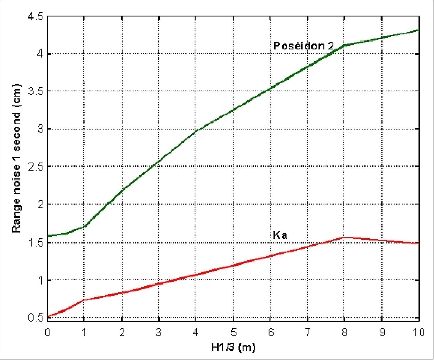
The range measurement accuracy versus wave height is illustrated in Figure 15. The improvement for AltiKa compared to Poseidon-2 is in the order of 3.
Center frequency | 35.75 GHz |
Pulse bandwidth | 500 MHz |
Pulse length | 110 µs |
PRF (Pulse Repetition Frequency) | ~ 3.8 kHz |
SSPA (Solid‐State Power Amplifier) output power | 2 W (peak) |
LNA (Low Noise Amplifier) noise figure | 3.9 dB |
SNR (Signal-to-Noise Ratio) for 6.5 σο (sigma naught) | 11 dB |
Antenna gain | 49.3 dB |
RF (Radio Frequency) losses (Tx & Rx) | 2.2 dB |
Atmospheric losses | 3 dB |
Radiometer design:
The instrument is a total power radiometer with a direct detection capability. It consists of two RF receivers, centered on 37 and 23.8 GHz, and a calibration unit enabling the connection of the receivers either to a sky horn pointing to provide a cold space reference or to a load at ambient temperature (hot reference).
In the nominal mode, the radiometer receivers measure the antenna temperatures (RM1 to RM5). In the internal mode, the receivers are either connected to a sky horn pointing to deep space or to a load at ambient temperature. This internal calibration can be performed every few seconds.
Center frequencies (altimeter band) | 35.75 GHz (Ka-band) |
Integration time | 200 ms |
Radiometric resolution | < 0.5 K |
Radiometric accuracy | < 3 K |
Dynamic range | 120 -300 K (3 K calibration) |
Antenna gains | K-band = 0 45.9 dB |
Antenna beam efficiencies | K-band = 93.0 % |
The critical technologies for AltiKa development concern the Ka-band functions except for the radiometer receivers that are taken from the receivers of the Megha-Tropiques mission (ISRO/CNES).
This includes:
• The multi-frequency antenna
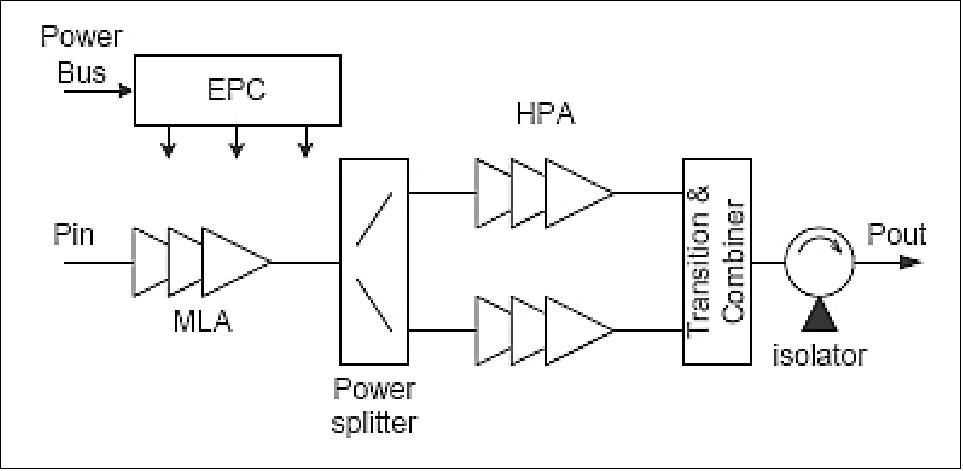
• The Ka-band SSPA (Solid State Power Amplifier)
• The Ka-band LNA (Low Noise Amplifier)
• The Ka-band radiometer calibration unit
• The Ka-band altimeter duplexer equipment (ADE)
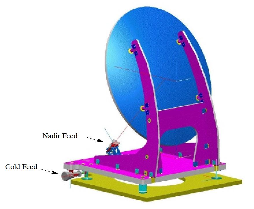
The AltiKa antenna (Figure 16) is a fixed offset reflector (1 m aperture diameter, 0.7 m focal length, 0.1 m offset) with a tri-band feed (35.5 - 36 GHz, 23.6 - 24 GHz, 36.5 - 37.5 GHz). The feed includes an OMT (Ortho-Mode Transducer) device for the separation of the altimeter and radiometer channels which use perpendicular polarizations, and a diplexer for the separation of the radiometer (K-band, Ka-band) channels.
The characteristics of the SSPA are the following: gain of 35 dB, useful bandwidth of 500 MHz, and output power of 2 W (33 dBm). The power dies are being built in D01PH technology of OMMIC, France. The output combiner is in waveguide technology to minimize losses. All RF components of the SSPA are provided with a pulsed power converter to minimize power consumption and dissipation, and to decrease the junction temperatures of the components.
The real-time telemetry data rate of AltiKa (altimeter+ radiometer) is about 43 kbit/s.
RCU (Radiometer Calibration Unit). The RCU consists of two separate channels operating in the K- and Ka-bands. Two ferrite switches are provided in each channel to allow the selection of one of the three different operational paths, corresponding to each of the operational modes. Each channel uses a very low VSWR waveguide load, which acts as the “hot” calibration source. Additionally, the Ka-band channel contains a bandpass filter to improve the isolation between the RCU channels and the altimeter.
The ADE (Altimeter Duplexer Equipment) consists of a single ferrite switch on the transmit path and four ferrite switches on the receive path. The transmit and receive paths are connected via a ferrite circulator which also provides a directional path to and from the antenna port. Two cross-guide couplers provide the calibration path. The RCU and the ADE are developed at COM DEV, UK.
Item/subsystem | Mass (kg) | Volume (mm) | Power consumption (W) |
ORA (Offset Reflector Antenna) | 16 | 1230 x 1010 x 905 | - |
DPU (Digital Processing Unit) | 9 | 230 x 300 x 250 | < 29 |
AMU (Altimeter Microwave Unit) | 8 | 325 x 305 x 250 | < 39 |
RMU (Radiometer Microwave Unit) | 1.6 | 180 x 170 x 50 | < 4 |
RCU (Radiometer Calibration Unit) | 2.3 | 300 x 240 x 80 | < 3 |
Harness | 3 | - | - |
Total | 40 |
| < 75 |
Parameter | Ka channel | K channel | ||
Results | Specifications | Results | Specifications | |
Radiometer integration time | 180 to 210 ms | 200 ms | 180 to 210 ms | 200 ms |
Antenna beam efficiencies | 97.7% | 96% | 95.5% | 94% |
Sensitivity: (including antenna reflector contribution) | < 0.19 K | < 0.4 K | < 0.17 K | 0.3 K |
Absolute accuracy | < 0.44 K | < 2 K | < 0.4 K | < 2 K |
Absolute accuracy |
| < 3 K |
| < 3 K |
Instrument linearity | > 99.92% | > 99.84% | > 99.94% | > 99.84% |
DORIS (Doppler Orbitography and Radiopositioning Integrated by Satellite)
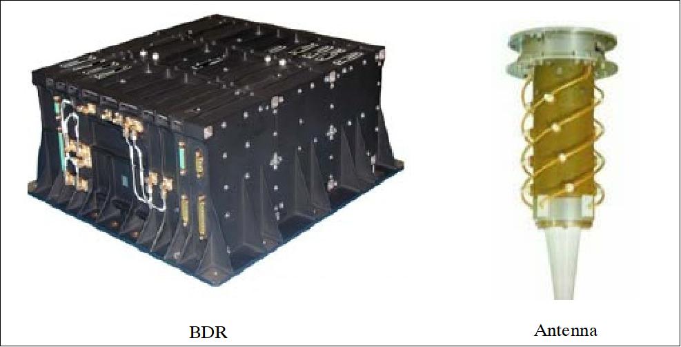
DORIS is a dual-frequency tracking system (400 MHz and 2 GHz) based on a network of emitting ground beacons spread all over the world. The DORIS onboard package is composed of:
• A dual-frequency antenna (omnidirectional antenna located on the nadir face of the satellite). The antenna has a mass of 2 kg and a size of 420 mm (length) and 160 mm in diameter.
• A BDR (DORIS Redundant Box) which is composed of two DORIS chains in cold redundancy accommodated inside the same electronic box. Each DORIS chain includes an MVR (Mesure de Vitesse radiale) unit achieving beacon signal acquisition and processing, navigation, Doppler measurements storage and formatting, electrical satellite interfaces management functions, and a USO (Ultra-Stable Oscillator) delivering a very stable 10 MHz reference which is also used by the altimeter. BDR has a mass of 18 kg and a size of 390 mm x 370 mm x 165 mm.
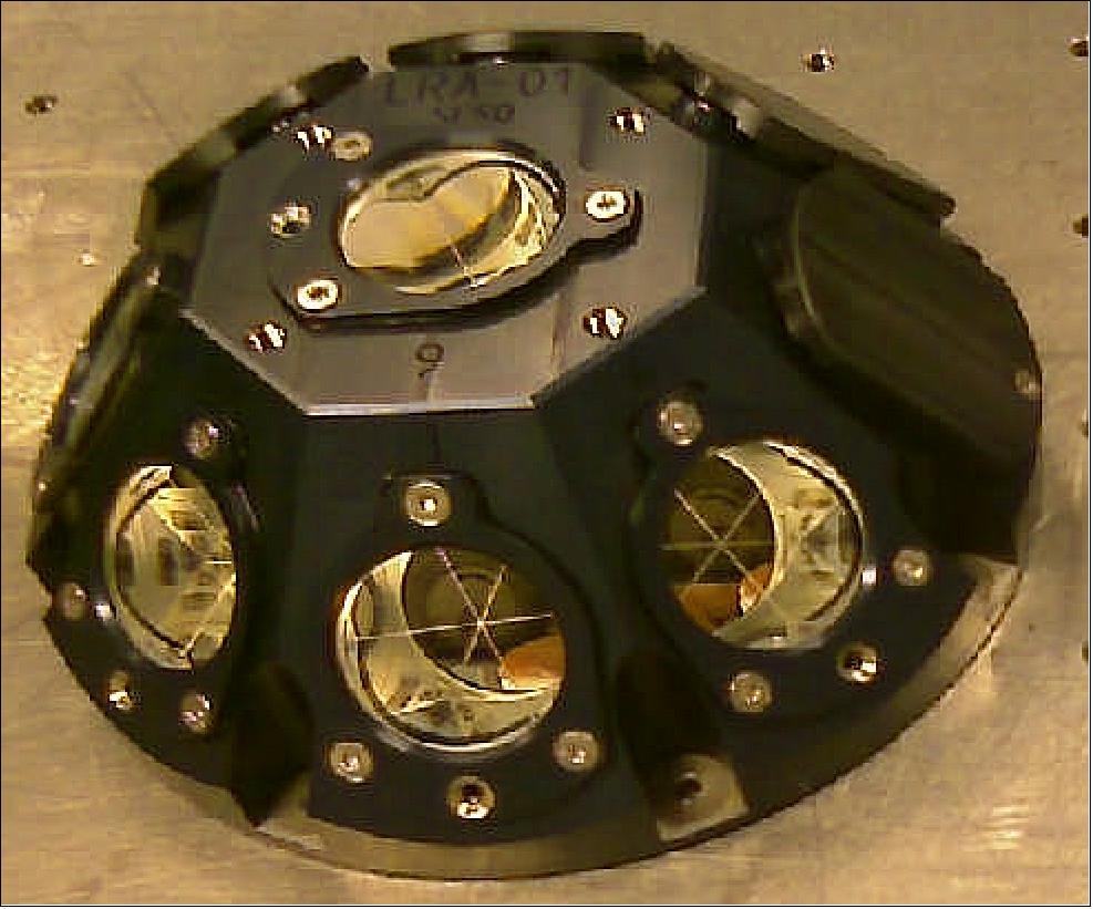
LRA (Laser Retroreflector Array)
LRA is provided by CNES. The objective of LRA is to calibrate the precise orbit determination system and the altimeter system several times throughout the mission. The LRA is a passive system used to locate the satellite with laser shots from ground stations with an accuracy of a few millimetres. The reflective function is done by a set of 9 corner cube reflectors, with a conical arrangement providing a 150º wide field of view over the full 360º azimuth angle. 39) 40)
According to CNES optomechanical specifications, the LRA has been developed by Thales SESO (Société Européenne de Systèmes Optiques), Aix en Provence, France (SESO is a Thales group subsidiary as of 2011). The corner cube reflectors were provided with a very stringent dihedral angle error of 1.6 arcsec and an accuracy within ±0.5 arcsec.
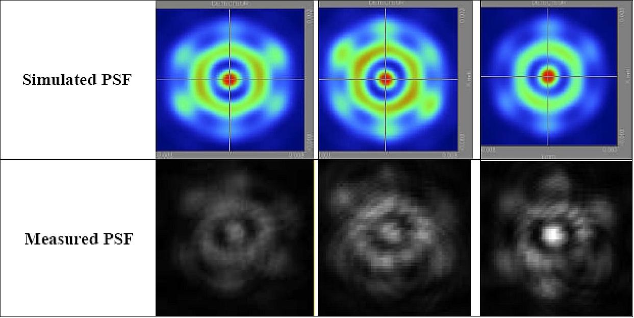
During the development phase, SESO has performed mechanical, thermal and thermo-optical analyses. The optical gradient of each corner cube, as well as the angular deviations and PSF (Point Spread Function) in each laser range finding direction, have been computed. The mechanical and thermal tests have been successfully performed. A thermo-optical test has successfully confirmed the optical effect of the predicted in-flight thermal gradients. Each reflector was characterized to find its best location in the LRA housing and give the maximum optimization to the space telemetering mission.
Mass, dimensions | 1.4 kg, 165 mm ∅ x 67 mm height |
FOV (Field of View) | > 150º |
For each corner cube, cone with optical performances | 50º |
Number of corner cubes | 9 |
Clear aperture of corner cubes | 30 mm |
Corner cubes:
The mean error is 0.17 arcsec and the maximum error is 0.42 arcsec! Due to this high accuracy, the real optical pattern will be very close to the model and within the required performances. The PSF has been characterized and analyzed for each corner cube. This verification has permitted them to confirm their position and orientation. The qualitative and quantitative verifications have been made by comparing the measured PSFs with the simulated analysis values. Figure 22 illustrates the analyses made.
Material | Suprasil |
Dimensions | 30 mm ∅ x 24 mm height |
Clear aperture of the corner cube | 30 mm |
Index of refraction at λ = 532 nm | 1.461 |
Operational dihedral offset angle | 1.5 arcsec |
Coating | Ag coating |
Radius of curvature of front face surface | Infinite |
Wavefront error | < 40 nm rms |
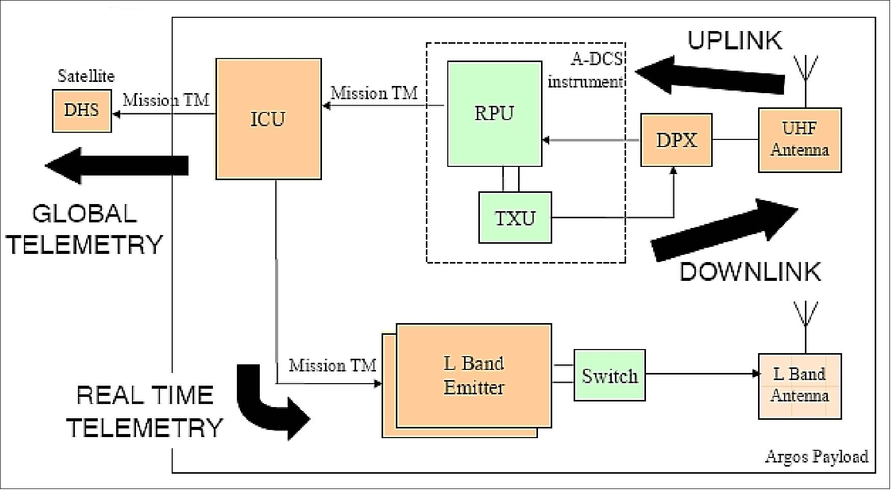
Argos-3 (Data Collection System)
Argos-3 of CNES, manufactured by TAS (Thales Alenia Space). The objective is to collect data from remote terminals in the ground segment referred to as PPTs (Platform Transmitter Terminals).
The Argos-3 onboard package represents the newest generation of the Argos system. The major improvement of the new Argos-3 system is that it will now be able to send orders to its terminals whereas before the onboard instruments were only capable of receiving data (up to Argos-2 inclusive). The MetOp-A spacecraft of EUMETSAT (launch Oct. 19, 2006) is carrying the first Argos-3 instrument demonstrator package. In comparison to previous generations, system performance is enhanced via a unique downlink and a high data uplink (4800 bit/s versus 400 bit/s), while insuring complete compatibility with existing systems in the ground segment. Thanks to digital processing, the new instrument is lighter and more compact than its predecessors on an analogue basis. Argos-3 is capable of receiving messages from over 1000 PTTs (Platform Transmitter Terminal) simultaneously within the satellite's FOV (Field of View). 41)
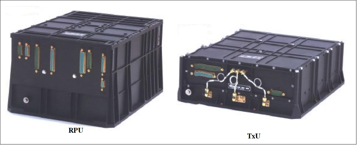
The Argos-3 onboard instrument is composed of the following components:
• The RPU (Receiver Processor Unit) provides the following functions:
- Processing of the received uplink signals
- Downlink management
- Interfaces with the receiver, the TxU and the satellite
• The TxU (Transmitter Unit) is sending the emissions (messages) to the PTTs in the ground segment including error-free message acknowledgement signals.
• The harness for the RPU to TxU connection
The RPU (16 kg, 36 W) and TxU (8kg, 26 W) boxes have a cold internal redundancy that can be activated by TC level. In the same way, the USO (Ultra Stable Oscillator) has a cold redundancy. RPU has dimensions of 365 mm x 280 mm x 365 mm, TxU has dimensions of 100 mm x 280 mm x 310 mm.
RPU (Receiver Processor Unit). The RPU onboard a spacecraft processes received uplink signals @ 401.6 MHz, measures the incoming frequency, time-tags the message, creates and buffers mission telemetry, manages the downlink and acts as interface between the receiver, the TxU (Transmitter Unit) and the satellite. Featuring fully digital processing, the RPU stores messages and either relays them in real-time to the nearest regional antenna - or in deferred time to a global center (maintained by NOAA, Eumetsat). A backup RPU is included as part of the device.
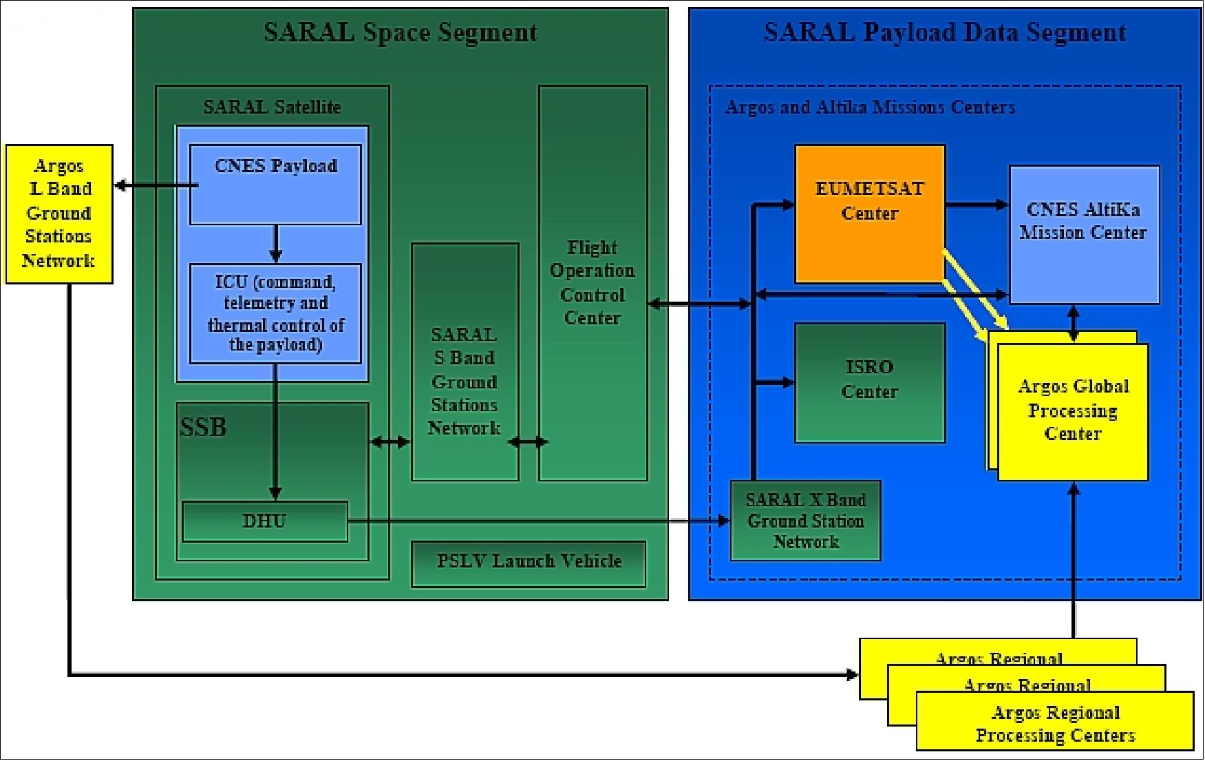
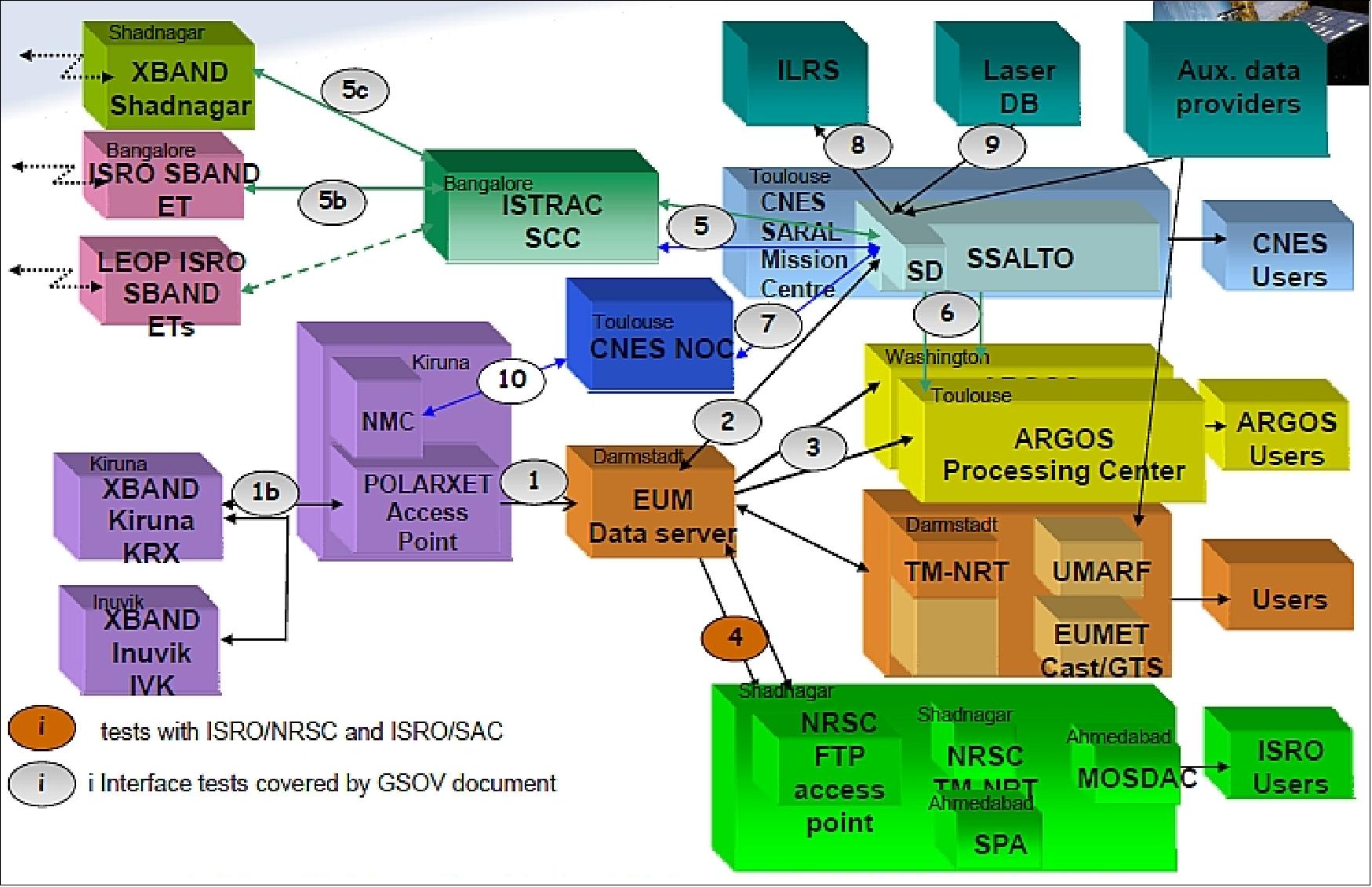
Ground Segment
According to the CNES-ISRO agreement: 42) 43) 44)
• CNES is responsible for the production, the archiving and the distribution of near-realtime altimetry products (OGDR: Operational Geophysical Data Record) and delayed products (GDR: Geophysical Data Record, IGDR, S-IGDR and S-GDR) to users outside India.
• Production of the mission preliminary and precise orbits is realized by CNES, from DORIS system data, completed by the laser system data, for the precise orbit. The operational upkeep of DORIS components and system is ensured by CNES.
• CNES uses EUMETSAT support for the operation of ground stations in Sweden, as well as to produce, archive and distribute near-realtime products to users outside India
• CNES supplies the near-realtime data processor to EUMETSAT and ISRO, as well as a support for its integration, test and operation
• CNES supplies the processor for delayed products to ISRO, as well as a support for its integration, test and operation
• ISRO is responsible for the production, the archiving and the distribution to Indian users of near-realtime and delayed-time altimetry products
• ISRO is responsible for the command-control operations of the satellite.
• All housekeeping and scientific telemetry as well as auxiliary data are archived by CNES and ISRO
• CNES and ISRO are responsible for the product enhanced value and the support to their respective users.
• CNES is responsible for the coordination of AltiKa with the other altimetry missions. The enhanced value products of DUACS (Data Unification and Altimeter Combination System) generated by CNES are archived and distributed under CNES responsibility.
• CNES is responsible for the expertise and the long term CalVal.
References
2) http://www.cnes.fr/web/5894-altika.php
3) J. Verron, F. Ardhuin, S. Arnault, P. Bahurel, F. Birol, P. Brasseur, S. Calmant, A. Cazenave, B. Chpron, J. F. Cretaux, P. De Mey, E. Dombrowsky, J. Dorandeu, L. Eymard, J. Lambin, J. M. Lefevre, B. Legresy, P. Y. Le Traon, F. Lyard, F. Mercier, E. Obligis, P. Sengenes, F. Seyler, N. Steunou, E. Thouvenot, J. Tournadre, “ARAL/AltiKa - An Altimetry mission in Ka-band,” 2010 OSTST (Ocean Surface Topography Science Team) meeting, Lisbon, Portugal, Oct. 18-20, 2010, URL: http://www.aviso.oceanobs.com/fileadmin/documents/OSTST/2010/oral/Verron.pdf
4) P, Vincent, N. Stenou, E. Caubet, L. Phalippou, L. Rey, E. Thouvenot, J. Verron, “AltiKa: a Ka-band Altimetry Payload and System for Operational Altimetry during the GMES Period,” IEEE Sensors 2006, Oct. 22-25, 2006, EXCO, Daegu, Korea, pp. 208-234, URL: http://www.mdpi.org/sensors/papers/s6030208.pdf
5) P. Sengenes, “ALTIKA / SARAL mission overview & status,” ISRO-CNES AltiKa Joint Science and Application Workshop, 22nd – 24th April, 2009 - ISRO/SAC Ahmedabad - India
6) A. Guillot, J. Lambin, J. Verron, P. Sengenes, J. Noubel, N. Steunou, N. Picot, R. Gairola, R. Murthy, “The SARAL/ALtiKa Mission: A Ka-band Mission for Ocean Mesoscale Studies in 2012,” Proceedings of the Symposium '20 years of Progress in Radar Altimetry', Venice, Italy, Sept. 24-29, 2012, (ESA SP-710, Feb. 2013)
7) J. Verron, N. Steunou, P. Baruhel, P. Brasseur, A. Cazenave, L. Eymard, P. Y. Le Traon, F. Remy, P. Sengenes, J. Tournadre, E. Thouvenot, P. Vincent, “AltiKa: A Microsatellite Ka-band Altimetry Mission,” ESA Workshop, Venice, Italy, “15 Years of progress in Radar Altimetry Symposium,” March 13-18, 2006, URL: http://earth.esa.int/workshops/venice06/participants/260/paper_260_altika.pdf
8) P. Vincent, E. Thouvenot, N. Steunou, J. Verron, P. Bahurel, C. Le Provost, P. Y. Le Traon, E. Caubet, L. Phalippou, “AltiKa3 : A high resolution ocean topography mission,” Proceedings of IGARSS 2002 Symposium, Toronto, Canada June 24-28, 2002.
9) P. Vincent, “AltiKa: a ka-band altimetry payload to contribute in ocean and ice observing systems,” 34th COSPAR Scientific Assembly, The Second World Space Congress, Oct. 10-19, 2002, Houston, TX, USA.,
10) “SARAL/AltiKa Flyer,” URL: http://www.aviso.altimetry.fr/fileadmin/documents/missions/Saral_AltiKA_flyer.pdf
11) E. Thouvenot, “CNES program status,” Proceedings of the OSTST (Ocean Surface Topography Science Team) 2009 meeting, Seattle WA, USA, June 22-24, 2009, URL: http://www.aviso.oceanobs.com/fileadmin/documents/OSTST/2009/oral/Thouvenot.pdf
12) D. V. A. Raghava Murthy, P. Sengenés, “ISRO-CNES SARAL Mission,” 58th IAC (International Astronautical Congress), International Space Expo, Hyderabad, India, Sept. 24-28, 2007, IAC-07-B1.1.09
13) P. W. Bousquet, C. A. Prabhak, 58th IAC (International Astronautical Congress), International Space Expo, Hyderabad, India, Sept. 24-28, 2007, IAC-07-C2.1.08
14) D. V. A. Raghava Murthy, K. Suresh, K. Kalpana, P. Veeramuthuvel, M. Annadurai, Nitin D. Ghatpande, “SARAL - First mission on modular Multi Mission Mini Satellite Bus,” Proceedings of the 63rd IAC (International Astronautical Congress), Naples, Italy, Oct. 1-5, 2012, paper: IAC-12-B4. 6A.4
15) D. R. M. Samudraiah, D. V. A. Raghava Murthy, “Small Satellites planned by ISRO for Earth Observation,” 58th IAC (International Astronautical Congress), International Space Expo, Hyderabad, India, Sept. 24-28, 2007, IAC-07- B4.4.8
16) “PSLV - C20 successfully launches Indo-French satellite SARAL and six other commercial payloads into the orbit,” ISRO, Feb. 25, 2013
17) Jacques Verron, Pascal Bonnefond, Ole Andersen, Fabrice Ardhuin, Muriel Bergé-Nguyen, Suchandra Bhowmick, Denis Blumstein, Francois Boy, Laurent Brodeauh, Jean-Franccois Crétaux, Mei Ling Dabat, Gérald Dibarboure, Sara Fleury, Florent Garnier, Lionel Gourdeau, Karen Marks, Nade`ge Queruel, David Sandwell, Walter H. F. Smith, E. D. Zaron, ”The SARAL/AltiKa mission: A step forward to the future of altimetry,” Advances in Space Research, Available online 3 February 2020, https://doi.org/10.1016/j.asr.2020.01.030
18) Jacques Verron, Pascal Bonnefond, Lofti Aouf, Florence Birol, Suchandra A. Bhowmick, Stéphane Calmant, Taina Conchy, Jean-François Crétaux, Gérald Dibarboure, A. K. Dubey, Yannice Faugère, Kevin Guerreiro, P. K. Gupta, Mathieu Hamon, Fatma Jebri, Raj Kumar, Rosemary Morrow, Ananda Pascual, Marie-Isabelle Pujol, Elisabeth Rémy, Frédérique Rémy, Walter H. F. Smith, Jean Tournadre, Oscar Vergara, ”The Benefits of the Ka-Band as Evidenced from the SARAL/AltiKa Altimetric Mission: Scientific Applications,” Remote Sensing, Vol. 10, 163, 2018, doi:10.3390/rs10020163, URL: http://www.mdpi.com/2072-4292/10/2/163/pdf
19) Pascal Bonnefond, Jacques Verron, Jérémie Aublanc, K. N. Babu, Muriel Bergé-Nguyen, Mathilde Cancet, Aditya Chaudhary, Jean-François Crétaux, Frédéric Frappart, Bruce J. Haines, Olivier Laurain, Annabelle Ollivier, Jean-Christophe Poisson, Pierre Prandi, Rashmi Sharma, Pierre Thibaut, Christopher Watson, ”The Benefits of the Ka-Band as Evidenced from the SARAL/AltiKa Altimetric Mission: Quality Assessment and Unique Characteristics of AltiKa Data,” Remote Sensing, Vol. 10, 83, 2018, doi:10.3390/rs10010083, URL: http://www.mdpi.com/2072-4292/10/1/83/pdf
20) ”SARAL/AltiKa Products Handbook,” Issue: 2 rev 5, July 1, 2016, URL: http://www.aviso.altimetry.fr
/fileadmin/documents/data/tools/SARAL_Altika_products_handbook_01.pdf
21) ”SARAL: three years in orbit!,” CNES, AVISO+, Feb. 25, 2016, URL: http://www.aviso.altimetry.fr/en/news/front-page-news/
news-detail.html?tx_ttnews[tt_news]=1934&cHash=22188636f9e96e324250932bcbfdbedd
22) Information provided by Thierry Guinle of CNES. Toulouse, France.
23) A. Guillot, J. Lambin, J. Verron, P. Sengenes, J. Noubel, N. Steunou, N. Picot, S.Coutin-Faye, “The SARAL/AltiKa mission : the first Ka-band altimetry mission,” Proceedings of the Advanced RF Sensors and Remote Sensing Instruments-Ka-band Earth Observation Radar Missions,” (ARSI'14 & KEO'14), ESA/ESTEC, Noordwijk, The Netherlands, Nov. 4-7, 2014
24) V. K. Dadhwal, “Recent Indian Space Miissiions: Update Feb 2014,” Proceedings of the 51st Session of Scientific & Technical Subcommittee of UNCOPUOS, Vienna, Austria, Feb. 11-22, 2014, URL: http://www.unoosa.org/pdf/pres/stsc2014/tech-22E.pdf
25) Remko Scharroo, Luciana Fenoglio, Alessandro Annunziato, “Cyclone Xaver seen by SARAL/AltiKa,” SARAL/AltiKa workshop, Konstanz, Germany, Oct. 27, 2014
26) “Saral, first verification workshop : main conclusions,” AVISO News, Sept. 5, 2013, URL: http://www.aviso.oceanobs.com/en/news-storage/
news-detail.html?tx_ttnews[tt_news]=1506&cHash=4f310d5ecff477de0dc9943125caa101
27) “The SARAL/AltiKa data are planned to be made available on EUMETCast, from 23 July 2013, as an early dissemination to users,” EUMETSAT, July 11, 2013, URL: http://www.eumetsat.int/website/home/News/DAT_2056160.html
28) “SARAL/AltiKa Products Handbook,” CNES/EUMETSAT/ISRO, Issue 2, Rev. 2, June 18, 2013, URL: http://www.eumetsat.int/website/wcm/idc/idcplg?IdcService=GET_FILE&
dDocName=PDF_SALP_PROD_HANDBK&RevisionSelectionMethod=LatestReleased&Rendition=Web
29) “SARAL/AltiKa LATEST NEWS,” CNES, URL: http://smsc.cnes.fr/SARAL/GP_actualite.htm
30) http://smsc.cnes.fr/SARAL/GP_actualite.htm
31) “SARAL/AltiKa LATEST NEWS,” CNES, March 8, 2013, URL: http://smsc.cnes.fr/SARAL/GP_actualite.htm
32) Jacques Richard, Benoit Durand, Frederic Robert, Nicolas Taveneau, Nathalie Stenou, Pierre Sengeres, “ALTIKA Instrument for Space Altimetry with Improved Performances and Ocean Sampling: Development Status and First Test Results,” Proceedings of IGARSS 2008 (IEEE International Geoscience & Remote Sensing Symposium), Boston, MA, USA, July 6-11, 2008
33) J. Richard, L. Phillippou, F. Robert, N. Stenou, E. Thouvenot, P. Senenges, “An Advanced concept of radar altimetry over oceans with improved performances and ocean sampling: AltiKa,” Proceedings of IGARSS 2007 (International Geoscience and Remote Sensing Symposium), Barcelona, Spain, July 23-27, 2007
34) J. Richard, E. Caubet, F. Robert, N. Stenou, E. Thouvenot, P. Senenges, “An Advanced concept of radar altimetry over oceans with improved performances and ocean sampling, AltiKa,” 58th IAC (International Astronautical Congress), International Space Expo, Hyderabad, India, Sept. 24-28, 2007, IAC-07-B1.3.06
35) Frédéric Robert, Jacques Richard, Benoît Durand, Nicolas Taveneau, Nathalie Steunou , Pierre Sengenès, “AltiKa, a Ka-band instrument for space altimetry with improved performances and ocean sampling: Instrument final test results,” Proceedings of the 2nd Workshop on Advanced RF Sensors and Remote Sensing Instruments 2009, Noordwijk, The Netherlands, Nov. 17-18, 2009
36) A. Guillot, J. Lambin, J. Verron, P. Sengenes, J. Noubel, N. Steunou, N. Picot, F. Robert, “The SARAL/AltiKa mission : a Ka-band mission for ocean mesoscale studies in 2012,” Proceedings of the 1st Workshop on Ka-and Earth Observation Radar, ESA/ESTEC, Noordwijk, The Netherlands, Oct. 8-9, 2012
37) Jacques Richard, Frédéric Robert, Nicolas Taveneau, Nathalie Steunou, Pierre Sengenès, “Integrated Altimeter / Radiometer AltiKa instrument for CNES/ISRO SARAL mission,” Proceedings of the 1st Workshop on Ka-band Earth Observation Radar, ESA/ESTEC, Noordwijk, The Netherlands, Oct. 8-9, 2012
38) “SARAL / AltiKa,” New Frontiers in satellite Altimetry, OSTST (2011 Ocean Surface Topography Science Team Meeting) 2011, San Diego, CA, USA, Oct. 19-21, 2011, URL: http://www.aviso.oceanobs.com
/fileadmin/documents/OSTST/2011/oral/03_Friday/Plenary/New%20Frontiers/
05%20Pierre%20SARAL-AltiKa%20San%20Diego%20OSTST%202011%2021-10-2011.pdf
39) Vincent Costes, Karine Gasc, Pierre Sengenes, Corinne Salcedo, Stephan Imperiali, Christian du Jeu, “Development of the Laser Retroreflector Array (LRA) for SARAL,” ICSO 2010 (International Conference on Space Optics), Rhodes Island, Greece, Oct. 4-8, 2010, URL: http://congrex.nl/ICSO
/Papers/Session%2012b/FCXNL-10A02-1933572-1-du%20Jeu_icso2010_development
%20of%20the%20Laser%20Reflector%20Array%20(LRA)%20for%20SARAL.pdf
40) Dennis Fappani, Deborah Dahn, Vincent Costes, Clement Luitot, “Thales SESO's hollow and massive corner cube solutions,” Proceedings of the ICSO (International Conference on Space Optics), Ajaccio, Corse, France, Oct. 9-12, 2012, Poster: ICSO-054
41) “Argos-3 on SARAL,” 43rd Argos OPSCOM, New London, CT, USA, June 2009, URL: http://www.docstoc.com/docs/128831260/OPS43-E13-Argos3-Saral
42) J. Noubel, P. Sengenes, “SARAL Project Overview - CNES Activities Progress Status,” 2nd SARAL-AltiKa Science Workshop, Ahmedabad, India, March 15-17, 2011, URL: http://www.aviso.oceanobs.com/fileadmin/documents/ScienceTeams/Altika_2011
/15Mar11/0_ProjectOverview/Sengenes_CNES%20SARAL%20project%20overview%20&
%20status%20Ahmedabad%202011_03_15.pdf
43) http://smsc.cnes.fr/SARAL/GP_segment_sol.htm
44) “Neelima Rani Chaube, Santanu Chowdhury, “SARAL Ground Segment & Data Products,” ISRO-CNES Joint SARAL-Altika Science & Application Workshop,” Ahmedabad, India, April 22-23, 2009
45) “Special Issue SARAL Newsletter #22,” December 19, 2023, URL: https://www.aviso.altimetry.fr/en/news/front-page-news/news-detail.html?tx_ttnews%5Btt_news%5D=2945&cHash=78cc4bf128012c2d95454d9438c757d8
46) “SARAL/AltiKa, 12 years old!,” February 25, 2025, URL: https://www.aviso.altimetry.fr/en/news/front-page-news/news-detail.html?tx_ttnews%5Btt_news%5D=3058&cHash=78cc4bf128012c2d95454d9438c757d8