SEOSat/Ingenio - Earth Observation Satellite of Spain
EO
ESA
Mission complete
High resolution optical imagers
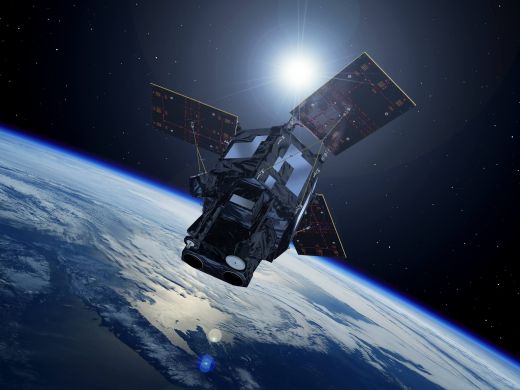
The Spanish System for Earth Observation Satellite (SEOSat) / Ingenio was an optical high-resolution satellite mission of Spain, in cooperation with the European Space Agency (ESA). The satellite had applications of cartography, land use monitoring, urban management, risk management and security. The satellite was launched in November 2020, although a failure in the Vega launcher shortly after liftoff created a trajectory deviation, resulting in the loss of the mission.
Quick facts
Overview
| Mission type | EO |
| Agency | ESA, CDTI |
| Mission status | Mission complete |
| Launch date | 17 Nov 2020 |
| End of life date | 17 Nov 2020 |
| Measurement domain | Land |
| Measurement category | Multi-purpose imagery (land), Vegetation |
| Measurement detailed | Land surface imagery, Land cover |
| Instruments | PAN+MS (RGB+NIR) |
| Instrument type | High resolution optical imagers |
| CEOS EO Handbook | See SEOSat/Ingenio - Earth Observation Satellite of Spain summary |
Summary
Mission Capabilities
The primary payload (PP) onboard SEOSat was a pushbroom imager composed of an optical panchromatic (PAN) and multispectral (MS) imaging detector in VNIR (Visible Near Infrared). SEOSat also contained a Complementary Scientific Payload (CSP) housing SENSOSOL, a solar sensor for orienting the satellite relative to the sun’s position.
The PP instrument included a panchromatic channel and four multispectral bands (red, green, blue and near-infrared). The instrument contained two identical barrel-mounted cameras, each covering half the instrument swath width, acquiring images simultaneously. The system was designed with four all-reflective mirrors, enabling observations from blue to near-infrared without chromatic aberration.
Performance Specifications
The PP operated in pushbroom mode, covering a swath of approximately 28 km in PAN and MS channels simultaneously, creating a total instrument swath of 55 km. The PAN and MS bands had spatial resolutions 2.5 m and 10 m, respectively. SEOSat had a daily imaging capacity of 2,500,000 km2 and capability for world coverage but focused mainly on the Spanish Territory. The satellite had a 38-day repeat cycle and a geo-location accuracy of 20 m.
SEOSat was planned to have a sun-synchronous circular orbit at an altitude of 670 km, an inclination of 98°, and an orbital period of 98 minutes. The satellite had a design life of 7 years.
Space and Hardware Components
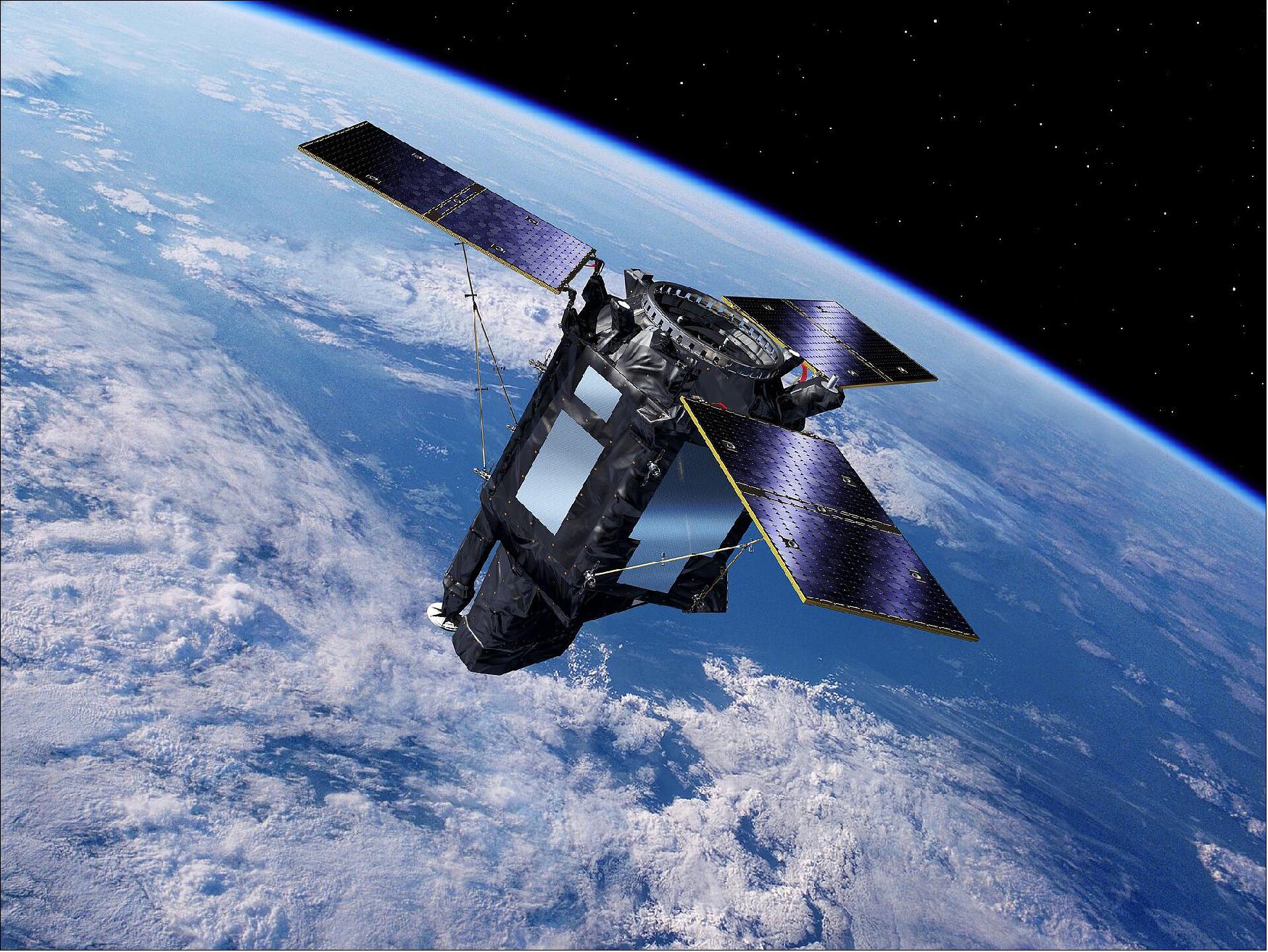
SEOSat was based on the AstroBus-250 platform by Airbus DS (Defence and Space), featuring an aluminium-faced sandwich panel design with fixed body mounted solar arrays. The spacecraft was three-axis stabilised with a gyroless Attitude and Orbit Control Subsystem (AOCS), also including a star sensor, magnetometers, four reaction wheels and a propulsion subsystem with four thrusters. The spacecraft had a launch mass of approximately 830kg. The satellite made use of S-band RF communications for TT&C (Telemetry, Transmission & Command) data transmissions. X-band communications are used for downloading imagery at 280 bit/s.
8 minutes into launch of Vega mission VV17, housing SEOSat and a secondary payload, an issue with the fourth stage thruster control system arose. This led to a deviated trajectory resulting in the subsequent loss of the mission.
SEOSat/Ingenio - Earth Observation Satellite of Spain
Spacecraft Launch Sensor Complement Ground Segment References
Overview
Ingenio, Spanish for "ingenuity", is an optical high-resolution imaging mission of Spain - the flagship mission of the Spanish Space Strategic Plan 2007-2011. The mission is devoted to providing high-resolution multispectral land optical images to different Spanish civil, institutional and government users, and potentially to other European users in the framework of Copernicus (formerly GMES) and GEOSS. The overall mission objective is to provide information for applications in cartography, land use, urban management, water management, environmental monitoring, risk management and security. The requirements call for panchromatic imagery of 2.5 m and multispectral imagery of 10 m resolution. 1) 2)
Ingenio is also known as SEOSat/Ingenio (Satélite Español de Observación de la Tierra - Spanish System for Earth Observation Satellite).
CDTI (Centro para el Desarrollo Tecnológico Industrial - Spain's Center for Development of Industrial Technology) is funding the mission and is responsible for the programmatic aspects of the program. The project development is overseen by ESA as a national contribution within the framework of Europe. A procurement assistance agreement to this effect was signed between ESA and CDTI in July 2007. Within the agreement, CDTI has entrusted ESA with the technical and contractual management of the industrial activities, thus being in charge of the procurement of the Space Segment and of the Ground Segment of the Ingenio system. 3) 4) 5)
The basic mission requirements are defined according to these main criteria:
• Provision of data services to comply with the Spanish institutional user needs. The global land mission's primary objectives call for a "Carpet mapping of Spain"+ image acquisition over main areas of interest (Europe, South America and North of Africa).
• The SEOSat/Ingenio mission is also regarded to provide complementary services to the GMES program, in particular to the objectives of the Sentinel-2 mission.
Background
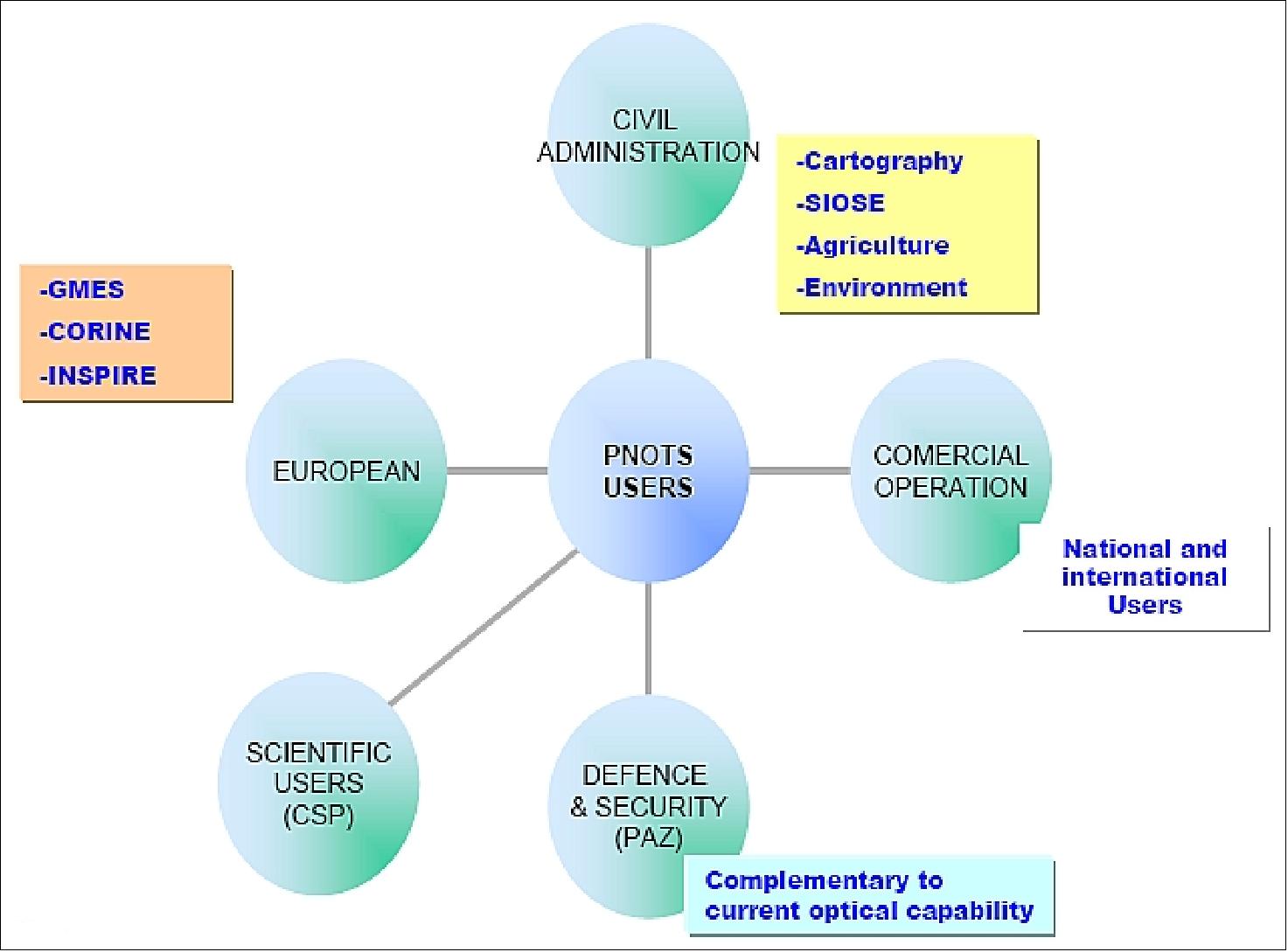
The Spanish Earth Observation Program, referred to as PNOTS (Programa Nacional de Observación de la Tierra por Satélite), is based on two complementary satellites, namely: 6) 7)
- SEOSat/Ingenio with the optical payload to serve the civilian users (space segment lead by CDTI/ESA)
- PAZ is an X-band SAR (Synthetic Aperture Radar) spacecraft based on the TerraSAR-X platform, to serve security and defence needs. The PAZ mission is a dual-use mission (civil/defence) funded and owned by the Ministry of Defence and managed by HISDESAT (Hisdesat Servicios Estratégicos, S.A., a Spanish mixed private-public communications company providing also its services to the Ministry of Defence (MoD), since 2001.
PNOTS is funded and owned by the government of Spain. INTA (Instituto National de Técnica Aeroespacial), the Space Agency of Spain, is managing the common ground segment of the two missions. Hisdesat together with INTA, will be responsible for the in-orbit operation and the commercial operation of both satellites. EADS CASA Espacio is the prime contractor leading the industrial consortia of both missions.
A major objective of PNOTS is to maximize the common developments, and services, and to share the infrastructure between both missions (whenever possible). Both missions will also contribute to the GMES (Global Monitoring for Environment and Security) program of Europe. According to the contract, the ESA SEOSat/Ingenio project team must ensure that the European ground segment will allow the SEOSat/Ingenio system to become a candidate national mission contributing to GMES and to participate in the ESA third-party mission scheme, within the EO multi-mission environment - and therefore to support HMA (Heterogeneous Mission Access) services.
The PNOTS program schedule calls for:
- March 2009: SSR (System Requirements Review)
- November 2009: PDR (Preliminary Design Review)
- Q4 2011: CDR (Critical Design Review)
- Launch of Ingenio in 2014.
- Launch of the PAZ spacecraft in 2014.
Mission and System Requirements | ||
Geographical coverage | World coverage, with latitudes from 83ºN to 56ºS. Systematic coverage of zones of special interest: | Including main world islands |
Imaging capacity | 2.5 x 10⁶ km2 / day with reference compression rates of: | Monthly average when available: |
Performance | - Pointing accuracy better than 200 m | Cross-track (2σ) |
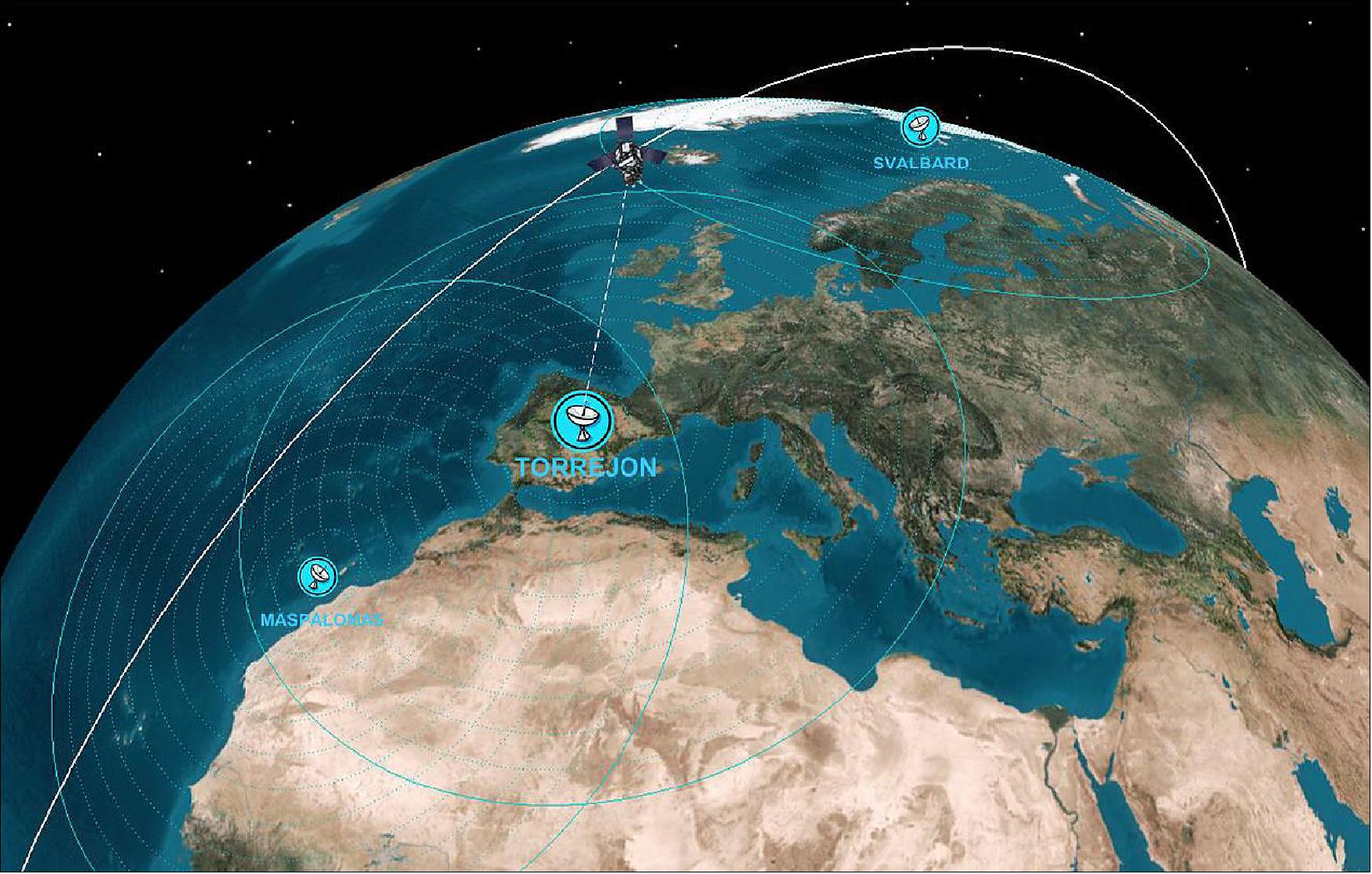
Ground segment baseline | Two TM/TC stations for command and control | Torrejón (Madrid region) and Maspalomas (Canary islands) ) and potentially additional high latitude station. |
Two stations for payload data reception | Torrejón and Maspalomas with capability to include high-latitude stations (one additional polar station is the baseline) | |
Sun-synchronous orbit | - Altitude of ~670 km | 38-day repeat cycle, 3 days accessibility |
Launcher | Based on Vega | Compatible with Rockot, PSLV, Dnepr and Soyuz |
Mission performance | - Lifetime = 7 years | Design and consumables sized for additional 3 years |
Primary Payload | ||
Spectral bands | - Panchromatic band | Pan |
Performance | - Swath of 55 km | Equivalent FOV= 5.13º |
Satellite | ||
Mass at launch | - Dry mass = 750 kg | Including all margins and propellant sized for 10 years |
Electrical power | Average power consumption = 580 W |
|
Payload data management | - X-band downlink = 280 Mbit/s | X-band TWTA (Travelling Wave Tube Amplifier) |
On-board data handling | - OBC = LEON3/SCOC3 (Spacecraft Controller On-a- Chip) | 1553 data bus |
Propulsion | Monopropellant: hydrazine, 80 kg | Sized for 10 years |
Spacecraft
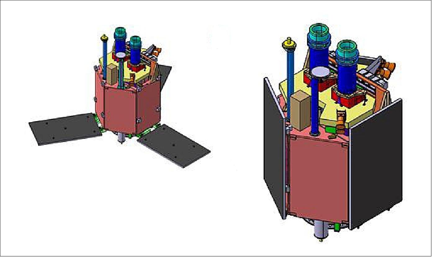
The SEOSat/Ingenio spacecraft contract was awarded to a consortium of Spanish companies led by Airbus Defence and Space (former EADS-CASA Espacio) of Madrid, Spain in 2008. The industrial team comprises a consortium of Spanish and other European industries, including as main partners SENER (Primary Payload Contractor), Thales Alenia Space España (Payload Electronics and Communication Systems), CRISA (Onboard platform electronics) and Airbus Space & Defence France (Avionics and Software).
The new medium-sized AstroSat-L platform (also referred to as AstroSat-250) is being used. The AstroBus-250 of Airbus DS is a standard modular ECSS (European Cooperation for Space Standards) compatible satellite platform compatible with an in-orbit lifetime of up to 10 years, with consumables sizeable according to the mission needs. The platform design is one-failure tolerant and the standard equipment selection is based on minimum Class 2 EEE parts, with compatibility to Class 1 in most cases. The AstroBus-L platform is designed for direct injection into LEO (Low Earth Orbit). Depending on the selection of standard design options, AstroBus-L can operate in a variety of LEOs at different heights and with different inclinations. Further implementations of the AstroBus-L platform are on the missions: Copernicus/Sentinel-2, and EarthCARE. 8)
An essential feature of AstroBus-L is the robust standard FDIR (Failure Detection, Isolation and Recovery) concept, which is hierarchically structured and can easily be adapted to specific mission needs.
The main features are:
- The service module has a box-shaped structure design with fixed solar array panels
- The configuration is based on an aluminum-faced sandwich panel structural concept, with fixed body mounted solar arrays.
- The payload is isostatically mounted on a service module structure, with a star tracker mounted directly onto the payload structure
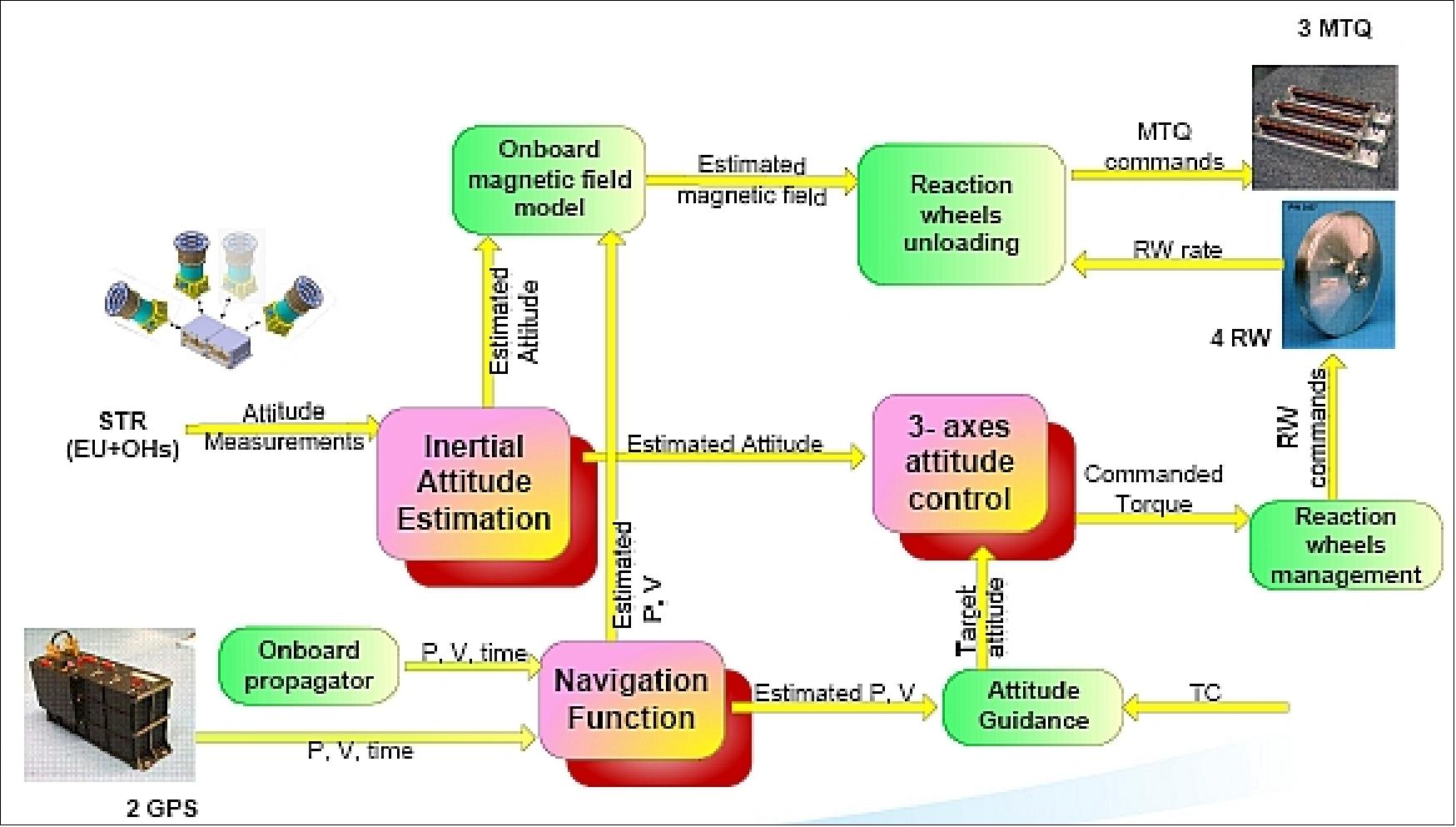
- The spacecraft is 3-axis stabilized. The AOCS (Attitude and Orbit Control Subsystem) architecture is based on a gyroless solution. Nominal attitude sensing is based on a multihead star sensor, CSS (Coarse Sun Sensors), and magnetometers; actuation is provided by 4 reactions wheels for fine-pointing and 3 magnetorquers (MTQs) for momentum off-loading. In addition, a propulsion subsystem with 4 thrusters is used. Redundant GPS receivers provide the real-time orbit and on-board time. The objective of the AOCS is to perform the functions of inertial attitude estimation, navigation and 3-axes attitude control. 9)
- The propulsion subsystem uses a plug-in concept, packaged on a single and compact module, with chemical monopropellant hydrazine
- The EPS (Electrical Propulsion Subsystem) uses solar panels with a total area of ~ 5.40 m2, a PCDU (Power Control and Distribution Unit), a Li-ion battery of 150 Ah capacity, and an unregulated power bus of 34 VDC
- Payload data handling comprises a >280 Mbit/s X-band data transmission, and a mass memory device of 1Tbit, allowing 33.17 Mpixel/s for the PAN output rate and 8.22 Mpixel/s for the MS output rate, for each optical camera unit
- The total mass of the spacecraft is about 830 kg at launch. 10)
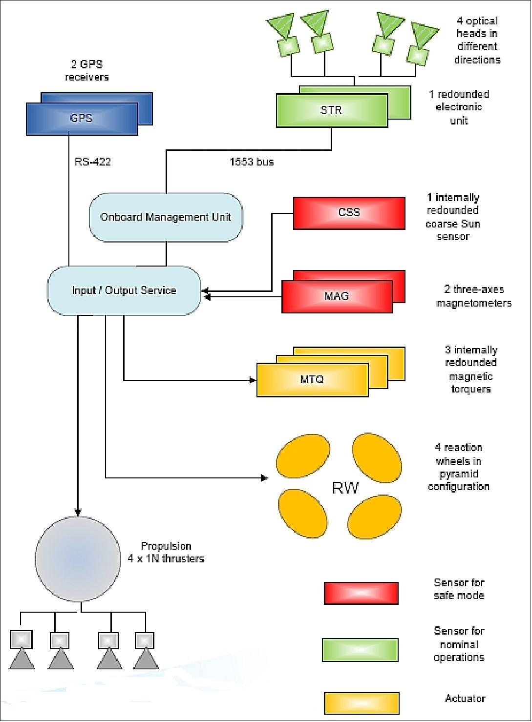
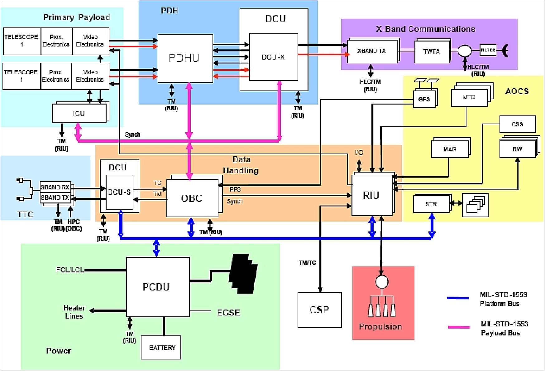
RF communications: Use of the S-band for TT&C data transmissions. The X-band is used for the download of imagery at 280 Mbit/s. Thales Alenia Space España is responsible to the development and delivery X-band and S-band data communication systems, and the electronics for optical observation instruments. 11)
Mission Status
• November 16, 2020: Dress rehearsals don't just happen on Broadway, they are a vital part of spacecraft launch preparations. After months of practising for a wide range of worst-case scenarios and ‘nominal' - perfect - lift-offs, the SEOSAT-Ingenio Flight Control Team recently went through the final practise-run, preparing to bring a new Earth observation satellite into orbit. 12)

- In the many simulations leading up to this point, the control team worked with a simulated version of the SEOSAT-Ingenio satellite, one which was designed to go wrong in a variety of unpredictable ways, preparing them for the many problems that can arise in space.
- On Saturday 14 November, for the first time, they were connected to the satellite on the launchpad in Kourou as well as with partners and colleagues around the globe who are working together to make this launch and 'early orbit' a possibility.
- The flagship SEOSAT-Ingenio is a mission of the Spanish Earth Observation Program, and will launch on Tuesday 17 November at 02:52 CET from Europe's spaceport in Kourou, French Guiana.
- Shortly after launch, the fledgling mission will establish communications with ESA's ESOC operations centre in Darmstadt, Germany, where teams will monitor and control the spacecraft during its intense first days in space, before handing over control to Spain's National Institute of Aerospace Technology (INTA) for routine operations.
- During SEOSAT-Ingenio's early days in space – the critical ‘Launch and Early Orbit Phase' – teams at ESA mission control will conduct a series of maneuvers to put it in its target orbit, communicating with the spacecraft using ground stations including ESA's own Kiruna station in Sweden.
- After safely guiding the satellite through this phase, ESOC will hand control over to an INTA control facility in Torrejón de Ardoz, Madrid, which will primarily communicate with it using their own ground station in Torrejón.
• November 10, 2020: As preparations for the launch of SEOSAT-Ingenio continue on schedule, the team at Europe's spaceport in Kourou have bid farewell to the satellite as it was sealed inside the rocket fairing. The spacecraft is currently scheduled to launch on the evening of Monday 16 November/morning of Tuesday 17 November. 13)
- SEOSAT-Ingenio, the new Spanish high-resolution land imaging mission, carries a state-of-the-art dual camera that can image Earth's land with a resolution of 2.5 m. The satellite will benefit society through numerous disciplines such as cartography, agriculture, forestry, urban development and water management.
- Since its arrival at the launch site in September, SEOSAT-Ingenio was put through a series of tests to make sure it is in good working order. Around two weeks ago, the satellite was fully fuelled, after which it was transferred to the Payload Processing Facility and was ‘mated' on top of the upper part of the Vega Secondary Payload Adapter.
- SEOSAT-Ingenio was then encapsulated in the rocket fairing, which protects it during the first part of the launch. The entire launch campaign team was there to wish farewell to the spacecraft as it was sealed from view.
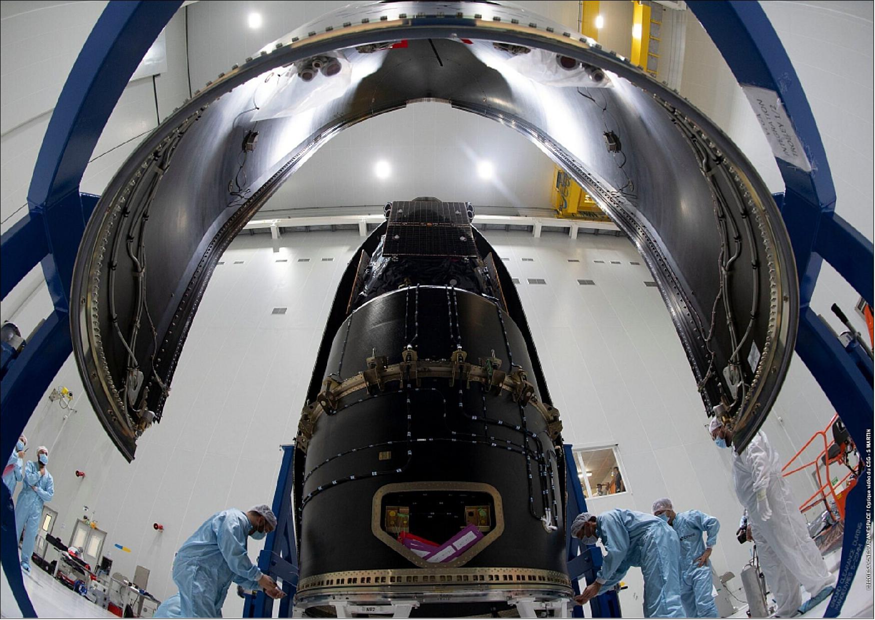
- ESA's Gianfranco Spinella commented, "The encapsulation marks a significant step on the road to launch. From now on, we no longer have physical or visual access to the spacecraft. This means it is ready to join the launch vehicle on the launch pad to start its long journey and provide the images and data it was built for.
- "This was a very emotional moment for all of us at the team here in Kourou, as well as for the many who have and are still contributing to the mission and cannot be present. This step in the launch campaign is primarily the result of the outstanding work performed by the prime industrial contractor Airbus Defence and Space - Spain. We are all very much looking forward to the launch next week!"
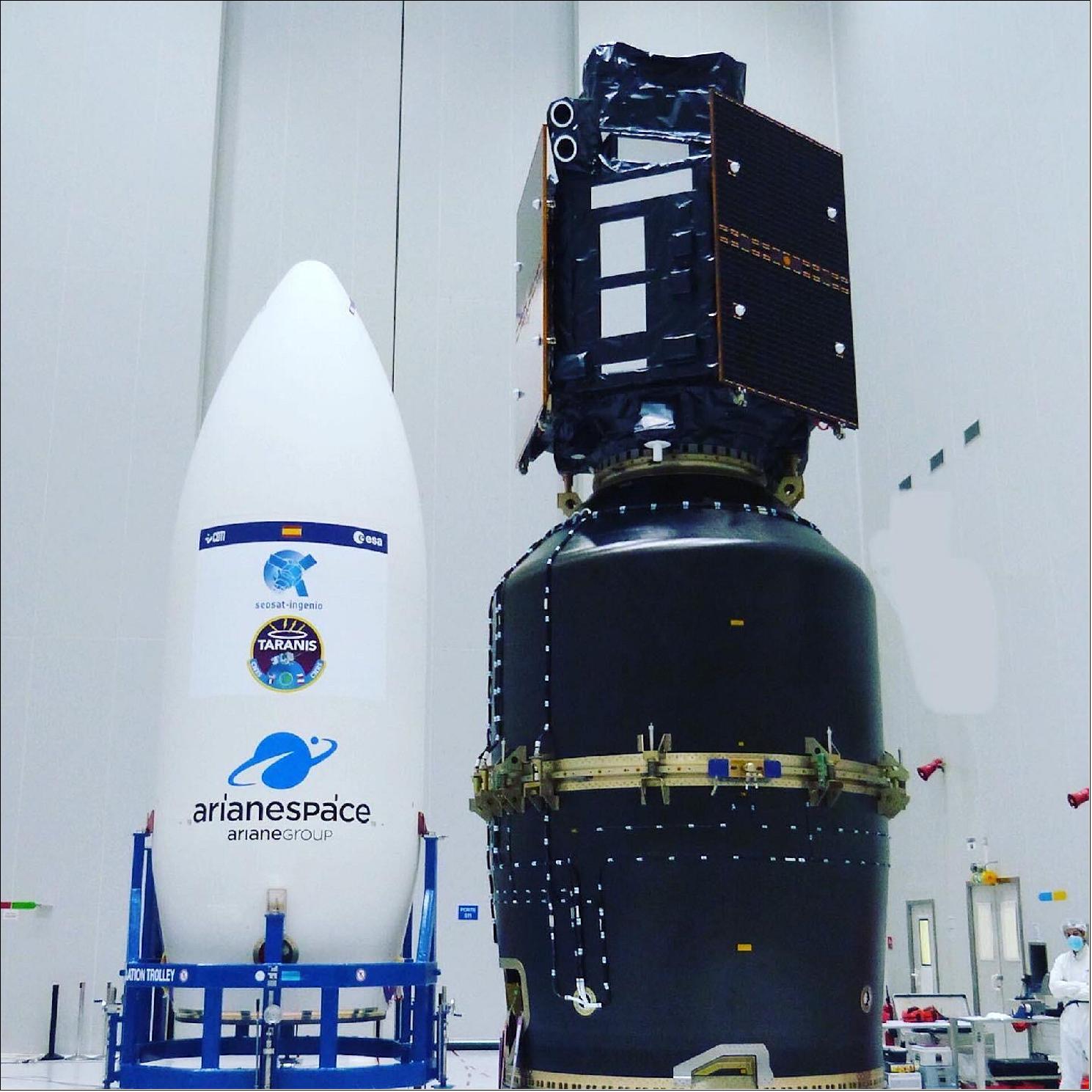
- The next important step for SEOSAT-Ingenio will take place on Wednesday 11 November, when the satellite will be rolled out to the launch pad. Then on 16 November, the satellite will be launched into orbit along with the French space agency CNES's Taranis satellite. SEOSAT-Ingenio will have a mass at liftoff of approximately 750 kg and will be placed in Sun-synchronous orbit at an altitude of around 670 km.
- While SEOSAT–Ingenio is a Spanish national mission, it is the result of an international collaborative effort. The mission is funded by Spain's Centre for the Development of Industrial Technology (CDTI) of the Ministry of Science and Innovation, but developed by ESA in the context of the European Earth Observation Architecture.
- Other partners include Airbus Defence and Space, being the prime industrial contractor of the satellite, and SENER & INDRA, responsible for the payload and ground segment.
- Information from SEOSAT–Ingenio will be used by different Spanish civil, institutional and government users, but also potentially by other European users in the framework of the European Union's Copernicus program and the Group on Earth Observations' Global Earth Observation System of Systems.
• October 22, 2020: Preparations are well on track for the upcoming launch of SEOSAT-Ingenio – the Spanish high-resolution land imaging mission – scheduled to launch from Europe's spaceport in French Guiana next month. 14)
- The SEOSAT-Ingenio team has successfully completed a series of inspections and health checks that confirmed the satellite is in good shape. This included several ‘leak tests' where the propulsion module's tank, valves and thrusters were tested at the ‘maximum expected over pressure' to verify their performances.
- Since then, SEOSAT-Ingenio was transported to the Filling Hall where it was loaded with around 80 kg of hydrazine fuel and was pressurized with helium gas to avoid the sloshing of the liquid during launch and flight. The satellite was then switched on – confirming the successful completion of its fuelling.
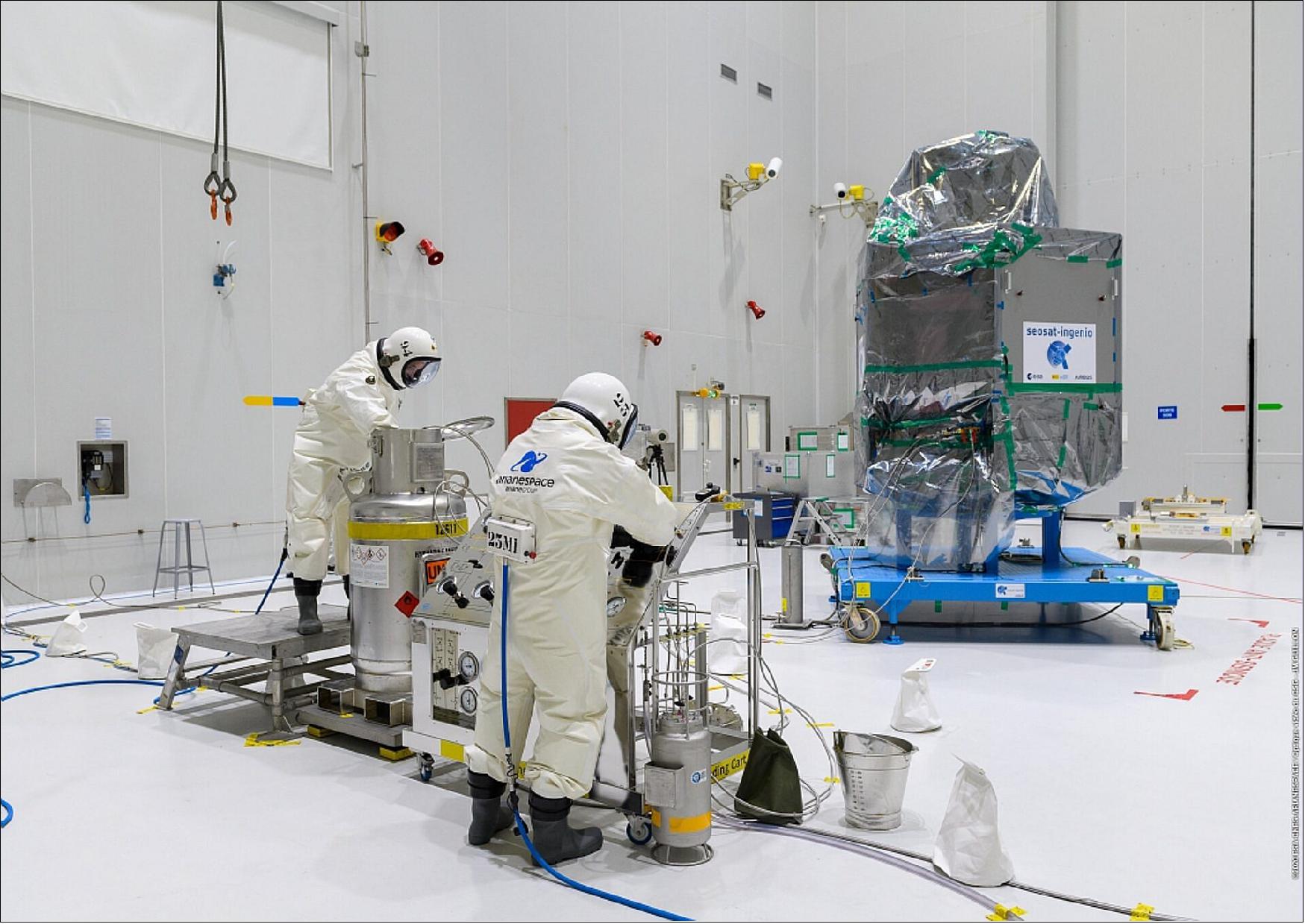
- ESA's Gianfranco Spinella commented, "The execution of the fuelling and pressurization operations were concluded with a successful switch-on of the spacecraft, which is yet another major milestone for this project. The amount of loaded propellant will cover SEOSAT-Ingenio for its 10 years of operations, three years more than its nominal mission lifetime.
- "These operations have completed the SEOSAT-Ingenio autonomous preparation phase. We are now looking forward to initiate the next phase of combined operations with the launcher next week."
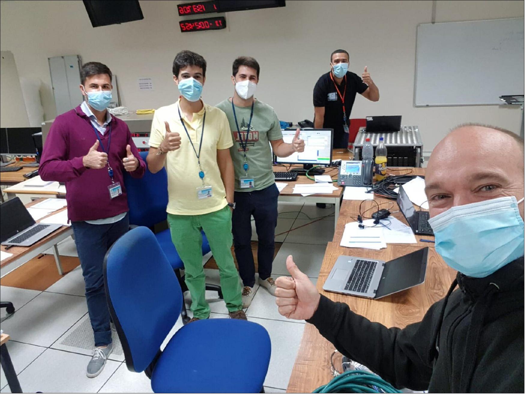
• October 12, 2020: Preparations are well on track to launch SEOSAT-Ingenio from Europe's spaceport in French Guiana in November. The launch campaign team in Kourou has carried out the ‘spacecraft internal countdown rehearsal', supported by the Launch and Early Orbit Phase team at ESA/ESOC in Darmstadt, Germany. This exercise verifies nominal and contingency spacecraft procedures for the night of the launch. 15)
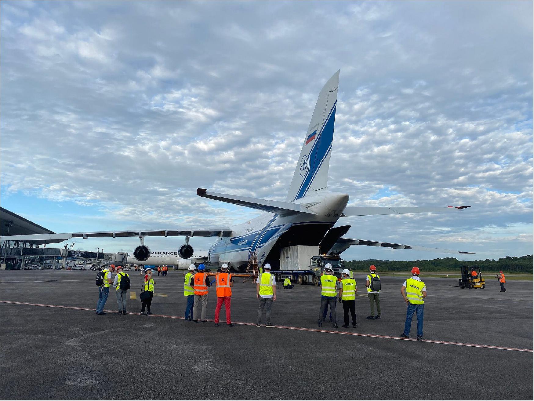
• September 25, 2020: After leaving the Airbus premises in Madrid on 24 September, the Spanish high-resolution land imaging mission, known as SEOSAT-Ingenio, has arrived safely at Europe's Spaceport in French Guiana, where it will be prepared for launch later this year. 16)
- Packed safely within protective containers, SEOSAT-Ingenio was transported together with its co-passenger, the CNES French space agency's Taranis satellite – both scheduled for launch on a Vega rocket in November. Following the airplane off-loading procedures, SEOSAT-Ingenio was then transferred on a dedicated trailer for transport to Guiana Space Centre.
- During the transfer, the convoy respected the speed limit of 50 km/h to avoid any shock to the satellite. After a journey of around two and a half hours, SEOSAT-Ingenio arrived at the Payload Preparation Complex. The arrival of the satellite marks a significant milestone for SEOSAT-Ingenio – an optical Earth-observation mission which will provide high-resolution images of Earth's land cover.
- ESA's Project Manager for the mission, Alex Popescu, commented, "I am extremely excited that the launch is getting closer, and so is the team and all of the major Spanish space companies who have contributed to the development of the satellite and its ground segment. We are looking forward to delivering this state-of-the-art Earth-imaging system."
- While SEOSAT–Ingenio is a Spanish national mission, it is the result of an international collaborative effort. The mission is funded by Spain's Centre for the Development of Industrial Technology (CDTI) of the Ministry of Science and Innovation, but developed by ESA in the context of the European Earth Observation Architecture.
- Jorge Lomba Ferreras, Project Manager from CDTI, said, "SEOSAT-Ingenio is the space program with the largest Spanish content ever, as Spanish industry is responsible for more than 80% of the industrial work. The capabilities developed by Spain for SEOSAT-Ingenio has been instrumental in the recent success of Spanish industry for Copernicus where, for the first time, Spain will be the prime contractor of a satellite developed by ESA with the European Commission as the final customer".
• September 22, 2020: SEOSAT-Ingenio, the Spanish high-resolution land imaging mission, will soon be shipped from Airbus, in Madrid, to Europe's Spaceport in French Guiana - where it will be prepared for launch later this year on a Vega rocket. 17)
- With its capability to look sideways, it can access any point on Earth within three days, and will be used to help map natural disasters such as floods, wildfires and earthquakes – as well as help with one of humankind's biggest challenges: understanding and responding to climate change. While SEOSAT–Ingenio is a Spanish national mission, it is the result of an international collaborative effort. The mission is funded by Spain's Centre for the Development of Industrial Technology (CDTI) of the Ministry of Science and Innovation, but developed by ESA in the context of the European Earth Observation Architecture.
• July 14, 2020: SEOSAT-Ingenio at the premises of Airbus in Madrid, Spain, being prepared for shipment to Europe's Spaceport in French Guiana. 18)
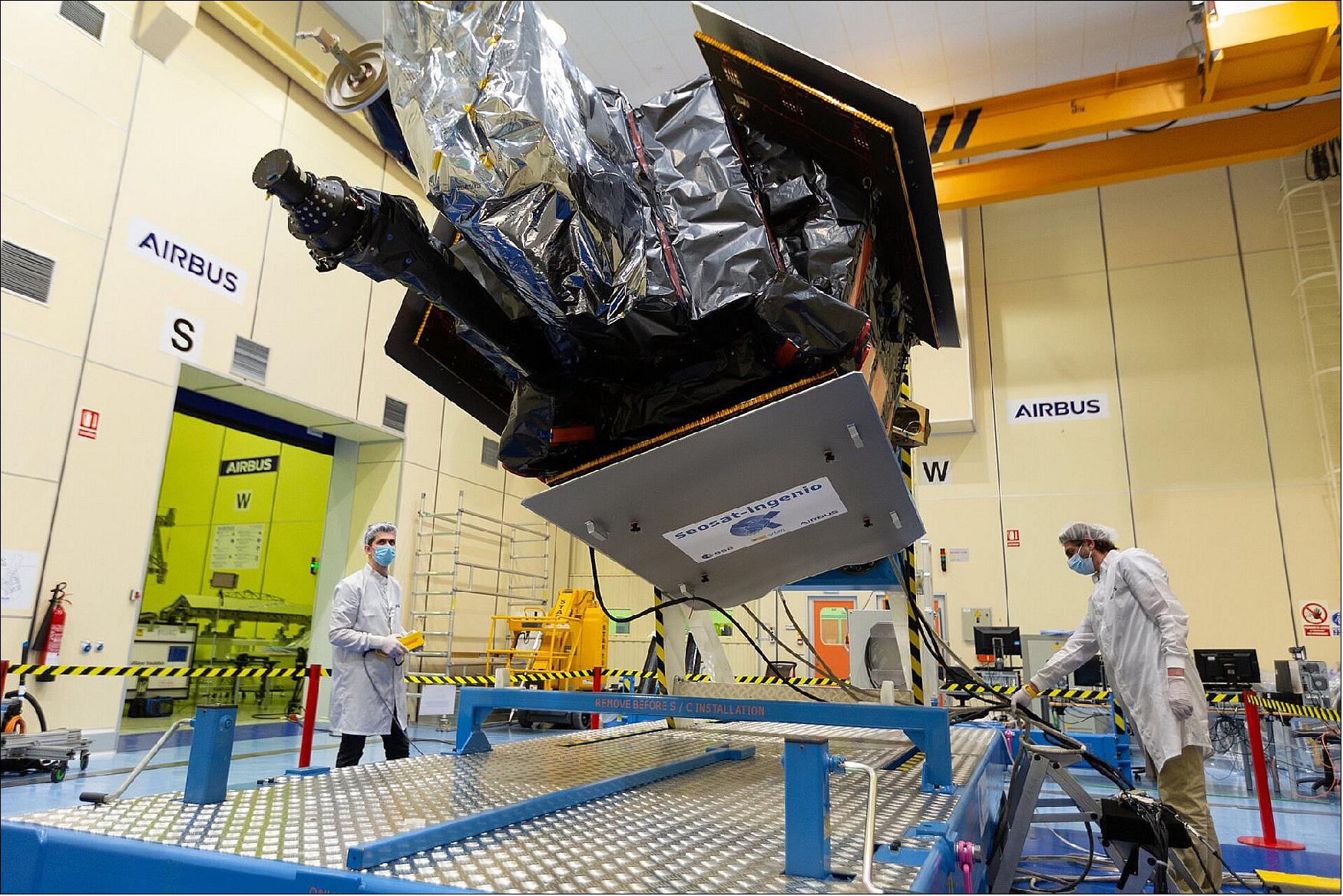
• June 15, 2020: The Spanish high-resolution land imaging mission, known as SEOSAT-Ingenio, is currently at the premises of Airbus in Madrid, Spain and is ready to be packed and shipped to Europe's Spaceport in French Guiana – following the mission's latest successful tests and final technical review. This is another significant milestone in preparing the Earth observation satellite's ride into orbit on a Vega rocket. 19)
- Thanks to the satellite era, we are better placed to understand and monitor the complexities of our planet, particularly with respect to global change. As the use of data from Earth observation satellites continues to be more commonplace, so does the demand for increasingly detailed imagery.
- High-resolution images of Earth are now deemed an essential commodity at the core of a wide range of scientific, commercial and governmental applications. By imaging Earth's land in remarkable detail, SEOSAT-Ingenio is ready to serve the new digital age.
- SEOSAT-Ingenio is based on a state-of-the-art dual camera that can image Earth's land with a resolution of 2.5 m. The mission will benefit society through numerous disciplines such as cartography, agriculture, forestry, urban development and water management.
- With its capability to look sideways, it can access any point on Earth within three days, and will be used to help map natural disasters such as floods, wildfires and earthquakes – as well as help with one of humankind's biggest challenges: understanding and responding to climate change.
- SEOSAT-Ingenio's latest tests, which took place virtually owing to COVID-19 restrictions, were deemed successful by teams working together across Europe. These recent assessments come after the successful technical review was completed in April.
- While SEOSAT–Ingenio is a Spanish national mission, it is the result of an international collaborative effort. The mission is funded by Spain's Centre for the Development of Industrial Technology (CDTI) of the Ministry of Science and Innovation, but developed by ESA in the context of the European Earth Observation Architecture.
- Other partners include Airbus Defence and Space, being the prime industrial contractor of the satellite, and SENER & INDRA, responsible for the payload and ground segment.
- Information from SEOSAT–Ingenio will be used by different Spanish civil, institutional and government users, but also potentially by other European users in the framework of the European Union's Copernicus program and the Group on Earth Observations' Global Earth Observation System of Systems.
- The target launch date is currently set for 24 August 2020 – to be confirmed by Arianespace.
• On 4 March 2020, the QAR-KO (Qualification Acceptance Review Kick Off) meeting took place at CDTI. Once the review process is finished, the QAR board will meet on 24/04/2020 and then it is expected the satellite to be declared qualified for flight. The satellite will be send to Kourou in mid May. 20)
• June 18, 2019: Airbus built the SEOSAT/Ingenio, the first Earth observation satellite for the European Space Agency (ESA) and Spanish government has left Madrid and is ready for final testing. 21)
- The spacecraft will now start a 3 month environmental test campaign which includes the Thermal Balance and Vacuum test, followed by Mechanical Vibration, Acoustic and Electromagnetic Compatibility testing. Fifty engineers and technicians from Airbus Spain will carry out all the different tests at Airbus in Toulouse.
- SEOSAT/Ingenio will be transported back to the Madrid-Barajas site in mid-September where the last functional tests will be carried out. The compatibility with the ground segment and the launcher will also be verified. Once these are complete, the Qualification Acceptance Review will take place, which is the final ESA milestone and the satellite will be ready to be launched. - The launch is scheduled for the first half of 2020 onboard a Vega launcher from Kourou, French Guiana.
- Once in orbit, SEOSAT/Ingenio will complete Spain's Earth observation system, complemented by the PAZ satellite already in orbit since February 2018. Together, they will provide combined radar and optical images.
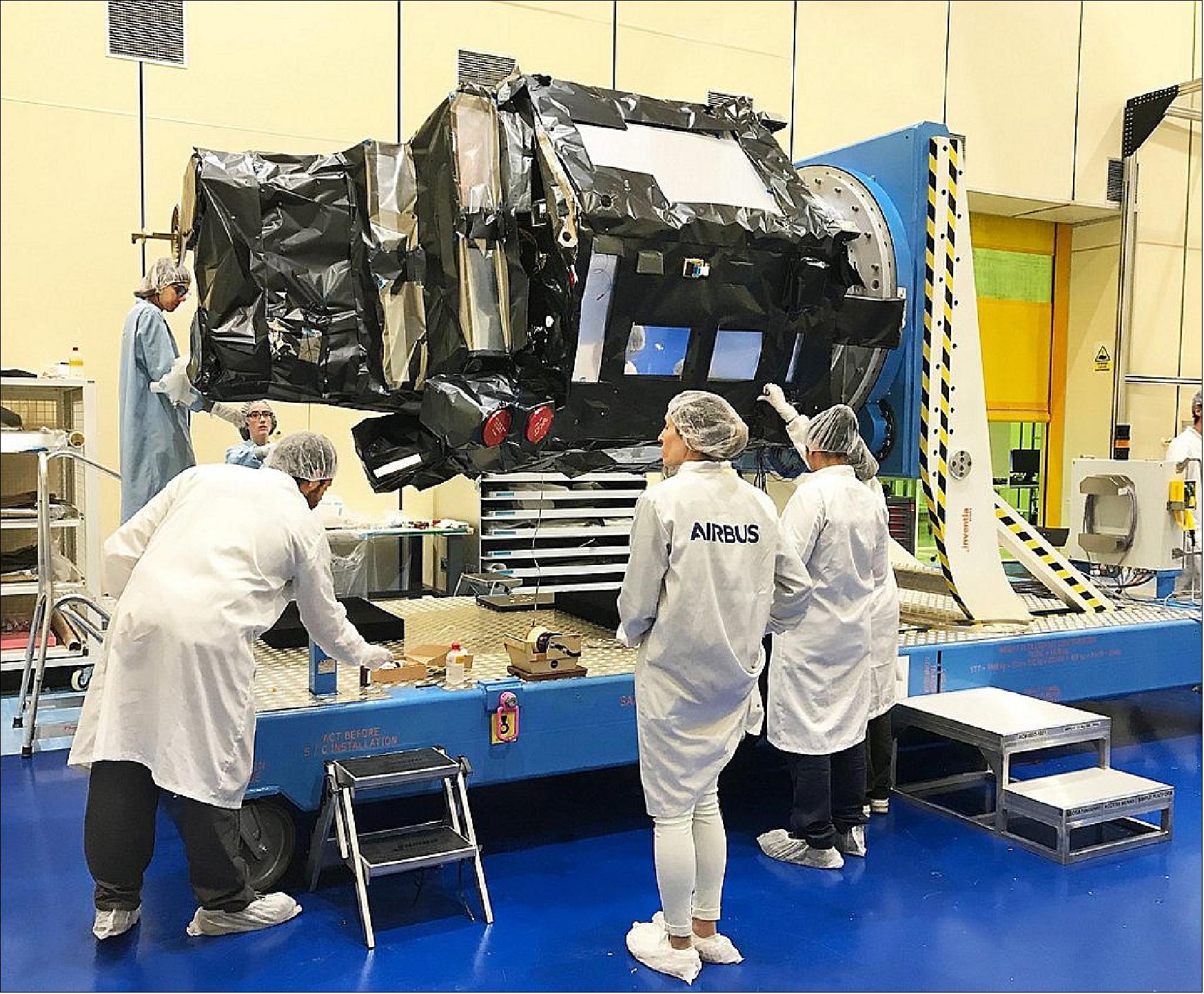
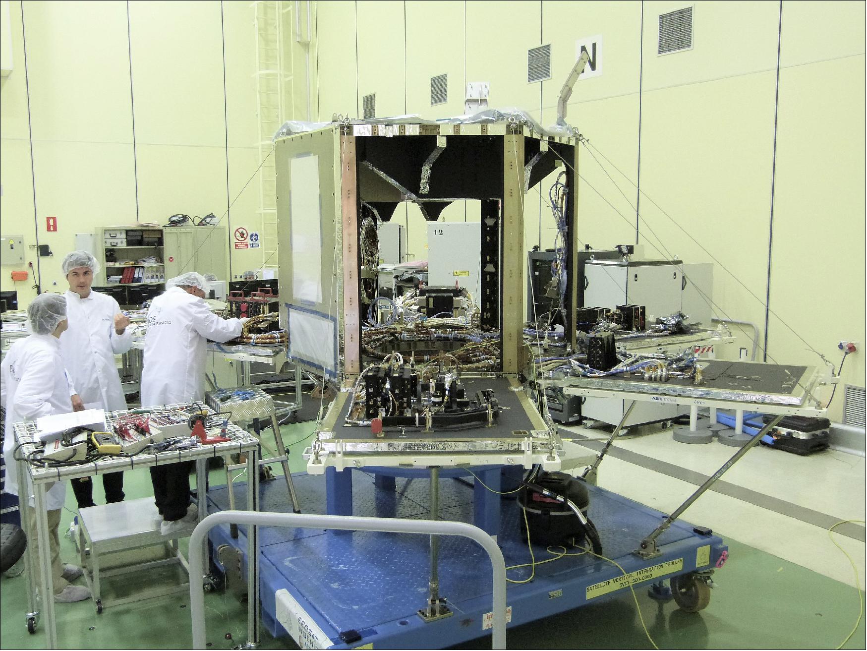
• June 5, 2019: SEOSAT in the cleanroom. 22)
Launch
The SEOSat/Ingenio spacecraft was launched on 17 November 2020 (01:52:20 UTC) on a Vega vehicle (designated VV17) from Kourou. A secondary payload on this mission is Taranis (Tool for the Analysis of Radiation from lightning and Sprites), a minisatellite of CNES.
A launch failure occurred 8 minutes after liftoff of Vega mission VV17, following the first ignition of the engine of the AVUM upper stage, a deviation of trajectory was identified, entailing the loss of the mission. 23)
Orbit: Sun-synchronous circular orbit, altitude = 670 km, inclination = 98º, LTDN (Local Time on Descending Node) at 10:30 hours, repeat cycle = 38 days.
• On Tuesday 17 November 2020, Arianespace announced the loss of the Vega VV17 mission, carrying two payloads: SEOSAT-Ingenio for ESA and TARANIS for the French space agency, CNES.
- Two and a half months after Vega's successful return to flight, the Vega launch vehicle lifted off as scheduled on 17 November at 02:52 CET / 22:52 local time on 16 November from Europe's Spaceport in Kourou, French Guiana. The first three stages functioned nominally until the ignition of the AVUM upper stage, eight minutes after departure from the launch pad. At that time, a degraded trajectory was detected, followed by a loss of control of the vehicle and the subsequent loss of the mission.
- The launcher fell in a completely uninhabited area close to the drop zone planned for the Zefiro-9 stage.
- Initial investigations, conducted overnight with the available data, indicate that a problem related to the integration of the fourth-stage AVUM nozzle activation system is the most likely cause of the loss of control of the launcher.
- In accordance with their standard protocols, Arianespace and ESA will set up an independent Inquiry Commission jointly chaired by Daniel Neuenschwander, Director of Space Transportation at ESA, and Stéphane Israël, Arianespace Chief Executive Officer, on 18 November. The Commission will provide detailed evidence to explain why steps were not taken to identify and correct the integration error. The Commission will formulate a road map for Vega's return to flight under conditions of complete reliability. Arianespace and ESA will jointly present the findings of this commission.
- "My thoughts are with all teams in particular at CDTI and at CNES for their hard work on the two lost satellites," commented ESA Director General Jan Wörner. "I will personally make sure that we fully understand the root cause, but also that we bring Vega back to the robustness and reliability of service it has shown since its first launch in 2012."
- ESA developed SEOSAT–Ingenio as a Spanish national mission as a result of an international collaborative effort. It was funded by Spain's Centre for the Development of Industrial Technology (CDTI) of the Ministry of Science and Innovation. Other partners included Airbus Defence and Space, being the prime industrial contractor of the satellite.
- The Spanish high-resolution imaging mission, SEOSAT-Ingenio, was designed to provide high-resolution images of Earth's land cover. By imaging in remarkable detail, this satellite mission would have benefitted society in various ways such as for monitoring land use, for planning urban development and for managing water resources. With its capability to look sideways, it would have been able to access any point on Earth within three days, and could have helped map natural disasters such as floods, wildfires and earthquakes.
- ESA's Director of Earth Observation Programs, Josef Aschbacher, said, "We are all very sad for the loss of the SEOSAT-Ingenio land monitoring mission. But despite this loss, I want to recall that we have fully achieved the other objective, which is to build up a strong expertise in space systems in Spain. This was recently demonstrated by the signature of the industrial contract with Spanish industry as Prime of the Copernicus LSTM Expansion mission."
- Also on this flight was TARANIS, Tool for the Analysis of RAdiation from lightNIng and Sprites, an Earth observation microsatellite for the French space agency, CNES. It was designed to observe luminous, radiative and electromagnetic phenomena occurring at altitudes of 20 to 100 km over thunderstorms.
Launch Loss Investigation of an IEC (Independent Enquiry Commission)
• December 18, 2020: On November 17, Arianespace announced the loss of the Vega VV17 mission, which was carrying two payloads, SEOSAT-Ingenio, an Earth-science observation satellite for the European Space Agency (ESA), on behalf of Spain's Center for Development of Industrial Technology (CDTI), and TARANIS for France's National Centre for Space Studies (CNES). The first three stages functioned nominally until the ignition of the AVUM upper stage, eight minutes after liftoff. At that time, a degraded trajectory was detected, followed by a loss of control of the vehicle and the subsequent loss of the mission. 25)
- Initial investigations, conducted right after the launch with the available data, identified a problem related to the integration of the fourth-stage AVUM Thrust Vector Control (TVC) system as being the most likely cause of the loss of control of the launcher.
- Arianespace (the launch service provider) and the European Space Agency (ESA – the launch system development authority) immediately set up an Independent Enquiry Commission (IEC). The Commission provided the detailed report and conclusions confirming initially identified root causes to the failure, comprehensively explaining what went wrong in the integration process and why the error was not detected before flight. According to its findings, the Commission has accordingly formulated a road map for a robust Vega return to flight.
- More precisely, the IEC concludes that the VV17 cause of failure is not attributable to a flaw in the qualification of the design but to the wrong routing and connection of the control lanes of the electromechanical actuators of the AVUM upper stage Thrust Vector Control (TVC) system, inverting steering commands and causing trajectory degradation leading to the loss of the vehicle. The detailed series of causes are described as (i) a misleading integration procedure causing (ii) an inversion of electrical connections, not detected through (iii) the different control steps and tests executed between the integration of the AVUM upper stage and the final acceptance of the launcher due to some inconsistencies between specific requirements and prescribed controls.
- A comprehensive set of both immediate and permanent recommendations has been presented by the IEC to ensure safe and prompt return to flight, as well as to ensure launch vehicles reliability on the long term. The first set of recommendations include additional inspections and tests on the next two Vega launchers, whose hardware is already totally or partially produced, and workmanship. Permanent recommendations have been proposed to further mitigate the identified root causes, regarding the manufacturing, integration and acceptance processes on Vega assembly lines in Italy and its final acceptance in French Guiana.
- Starting this week, a task force steered by ESA and Arianespace has started implementing the roadmap proposed by the IEC and will thoroughly follow its implementation. A set of actions will be implemented by Vega's prime contractor Avio, under the supervision of Arianespace, as launch service provider, and ESA, as launch system development authority, in order to make possible the next Vega launch, VV18, still scheduled by Q1 2021 from French Guiana, and the following ones.
- "Thanks to their hard work in less than one month, the members of the Commission have confirmed the cause initially identified after the loss of control of the mission VV17," said Stéphane Israël, CEO of Arianespace. "The clarity of the conclusions presented by the Independent commission opens the way to immediate implementation by Avio, Vega's prime contractor, of the recommendations on their integration line, with the support from Arianespace and ESA. It may allow a return to flight by end Q1 2021, in full confidence to Vega's quality and competitiveness on the market."
- Daniel Neuenschwander, ESA Director of Space Transportation, said: "In the past few weeks, members of the Independent Inquiry Commission have done an exceptional work, with the support of the prime contractor Avio. The Commission has drawn a set of recommendations that once implemented should enable robust, reliable and even swift return to flight of Vega, contributing to secure Europe's autonomy of access to space."
SEOSat/Ingenio Security System
The Security System Architecture was defined by the SEOSAT system team, under the technical supervision of ESA. EADS Astrium Crisa contributed to the definition of the system architecture as part of the SEOSAT's system team, and was awarded with the contracts for the development of the DCUs (Deciphering and Ciphering Units) and the associated EGSE (Electrical Ground Support Equipment). The DCU Flight Models (FMs) have been delivered by the end of 2012, and are currently (2013) being integrated in the Satellite at the CASA-Espacio facilities. The security functions of the GS (Ground Segment)for the FOS (Flight Operation Stations) and PDGS (Payload Data Ground Station) have been specified by ESA and are currently under development by the GS subcontractor. 26) 27)
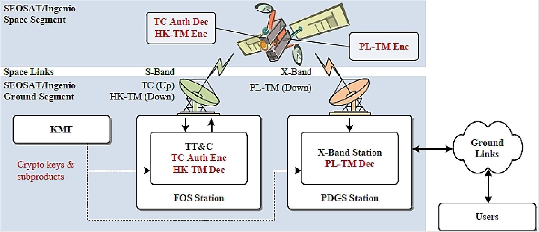
Security system architecture
The SEOSAT overall system is depicted in Figure 17. The Security System aims at protecting both the S-band and X-band space links between the satellite and the GS. For this purpose, complementary security functions have been allocated at the satellite and GS, namely:
• TC Authenticated Encryption ("Auth Enc") and Decryption ("Auth Dec"), and anti-replay protection
• Housekeeping TM Encryption ("HK-TM Enc") and Decryption ("HK-TM Dec")
• Payload TM Encryption ("PL-TM Enc") and Decryption ("PL-TM Dec").
SEOSat in LEO implies relatively short contact times with the GS. Therefore, the satellite is provided with a relatively high autonomy. Concerning the security system, the satellite is able to autonomously configure the security functions for routine operations. GS intervention is required basically for mission timeline uploads and troubleshooting. At the same time, given the short contact times, operational procedures and protocol overheads associated to the security system management are limited to the minimum necessary.
Besides technical requirements for the security functions, industrial organization constraints were considered for the definition of the security system architecture. The security functions had to be integrated within the satellite's platform without any major impact in the on-going development of other units or system functions. In addition, given the complex subcontractor network, the security perimeter (understood as the human team with direct knowledge about the security functions) had to be carefully limited. Finally, the security functions were the last to be specified and procured, with the subsequent pressure in schedule and cost. Given this scenario, it was decided to implement the security functions by purely hardware (HW) units and without involving the OBSW (On-Board Software) in them.
Security system architecture overview:
SEOSat's security system implements three functional DCUs, respectively, for TC authenticated decryption, HK-TM encryption and PL-TM encryption. The first two are packaged into a common housing, so two physical units have been developed: DCU-S (for S-band DCU) and DCU-X (for X-band DCU). DCU-S includes two hot redundant DCU-S (TC) modules and two cold redundant DCU-S (TM) modules. DCU-X includes two cold redundant modules. Both units are functionally placed in the S-band and X-band chains respectively, as shown in Figure 18.

The DCU-S(TC) module processes CLTUs (Communications Link Transmission Units) received from the Transponders (TRSPs) transparently for the OBC (On-Board Computer). The processing is done by a FPGA (Field Programmable Gate Array) and includes: CLTU delimitation, BCH decoding, de-randomization, Security Header extraction, TC Transfer Frame (TF) authenticated decryption and anti-replay control, pseudorandomization and BCH encoding. This module operates nominally at 64 kbit/s, but withstands up to 128 kbit/s.
The DCU-S(TM) module processes CADUs (Channel Access Data Units) received from the OBC transparently for the TRSPs. The processing is also done by a FPGA and includes: SP-L (Split-Phase-Level) line decoding, CADU delimitation, TF encryption and Security Header insertion (within secondary header), Reed-Solomon (RS) encoding, pseudo-randomization and SP-L encoding. VC (Virtual Channel) multiplexing is done by the OBC, so this module is not intended to insert (or remove) any additional bit in the bitstream. This module operates at two possible fixed rates, 1 Mbit/s and 128 kbit/s.
The DCU-X module processes CADUs received from the primary and secondary PDHUs (Payload Data Handling Units). The processing is also done by FPGAs and includes: input flow control, CADU delimitation, VC multiplexing, TF encryption and Security Header insertion (within insert zone), Reed-Solomon (RS) encoding, pseudo-randomization. The VC multiplexing is based on a Round-Robin scheduler, and Idle TFs are inserted automatically if no payload TF is available at the inputs. This module operates at fixed output rate of 280 Mbit/s, and withstands sustained input rates between 1 Mbit/s and 342 Mbit/s.
Crypto algorithms and keys:
All cryptographic algorithms used in SEOSAT are based on AES (Advanced Encryption Standard), and the modes of operation used are in accordance to the CCSDS recommended standard. 28) The algorithms are hard-coded in DCU's FPGAs. A set of cryptographic keys per functional DCU are available on-board. Part of them (session keys) can be updated in flight by means of secure commands, and part of them (master keys) are fixed throughout the mission. Keys are stored in DCU's non-volatile memory and are protected from potential corruption by means of triplication and EDAC (Error Detection And Correction) codes.
The initial key fill is performed while on ground via a dedicated connector on the satellite's skin (Key Fill I/F in Figure 18), and by means of a KFD (Key Fill Device). The KFD is a handheld battery-operated equipment that is used to transport the keys from the KMF (Key Management Facility) to the satellite, and to inject them directly into the DCUs (see also Figure 20). The Key Fill I/F is physically a "data diode", i.e. keys cannot be readout by any means once injected into the Satellite. As for any symmetric key system, the system security relies on the confidentiality of the keys. Anti-tamper mechanisms have been implemented in order to ensure DCU physical integrity while on ground.
Security function management:
Autonomous on-board monitoring of the DCUs is performed by the OBSW through the Mil-STD-1553 bus interfaces, and the associated HK-TM is also reported to GS. The DCUs can be managed from GS by means of the PUS (Packet Utilization Standard) TCs, which are processed by the OBSW. For non-security-related commands, plain TCs are used. For security-related commands (e.g. for key management), authenticated and encrypted messages are embedded into the TCs. When processed by the OBSW, these messages are decapsulated and blindly forwarded to the target DCU. The messages are finally decrypted and authenticated by the DCU's FPGA, and the resulting command is executed. This approach allows excluding OBSW from the security perimeter. Secure commands allow for example OTAR (Over-The-Air-Rekeying), key integrity checks and key disabling.
The security system can be operated in Secure Mode or Clear Mode, with security functions active or inactive, respectively. The satellite and the GS must be configured in the same mode and with the same crypto-parameters (if in Secure Mode), otherwise the TT&C may be interrupted. The security function configuration is nominally initiated by the GS, although in exceptional cases (e.g. autonomous reconfiguration) it can be initiated by the satellite.
Ground Segment constraints and operation:
SEOSAT's GS, specified by ESA and the satellite prime contractor, provides (among other information) the interface control documents, the mission operations concept and the satellite's user manual. For what the Security System and TT&C concerns, several constraints for the GS have been identified in these documents.
In general, TC TFs need to be encrypted, authenticated and sequence number stamped at uplink time while in Secure Mode, which implies that TT&C equipment shall process TC TFs on-the-fly. Optionally, pre-generated CLTUs could be uplinked by auxiliary FOS stations with no crypto-equipment, provided that the embedded TFs have sequential anti-replay stamps and use the COP-1 expedited service. However, the anti-replay acceptance window needs to be sized in order to avoid rejections in case re-transmissions are needed (e.g. due to channel errors). On the other hand, the on-board processing of some secure TCs can take longer than the minimum time specified for the inter-CLTU gap . In this case, the GS must insert a guard time (i.e. extend PLOP-2 CMM-4) after the TC.
Likewise, the HK-TM TFs need to be decrypted at downlink time while in Secure Mode by the TT&C equipment. However this is not strictly necessary, as the CLCWs (Command Link Control Words) in the TF Trailer fields are not encrypted (for any VC) and can therefore be extracted from the encrypted TF stream. Additionally, either in Clear or in Secure Modes, the Idle TFs are left un-encrypted, which allows the possibility of segregating the Idle TFs from the rest before the storage (if any) and decryption process. Regarding the PL-TM, in spite of the higher data rate, the TF processing on ground is less stringent for several reasons, namely: decryption can be performed off-line, the Idle TFs are also left un-encrypted (they can be discarded prior to storage and decryption), and the decryption function can process standalone PL-TM TFs with complete independence of previous TFs in the stream.
The satellite can initiate self-configuration under off-nominal situations, potentially configuring the satellite in an operational mode unexpected for the GS (different from the mode during previous contact). When this occurs outside the GS visibility, the TT&C link may be lost at the following pass. It is important for the operator to plan in advance how to handle such scenarios.
Since the PL-TM data on-board storage is massive, it may happen that a contact time is not long enough to complete the downlink of a big data file. The DCU-X implements input data flow override by command, allowing the operator to split the downlink along several contacts. Downlink in progress can be stopped preserving the encryption context, then resumed during the following contact.
Space data link protocols
SEOSat's Security Layer is implemented at the Transfer Sublayer of the TC link and HK-TM link applicable protocols, respectively, 29) 30) and at the Data Link Protocol Sublayer of the PL-TM link applicable protocol. 31) The applicable standard for the TM (both HK and PL) Synchronization and Channel Coding Sublayer is provided in reference. 32) The Security Layer was specified ad-hoc for the SEOSat mission during 2009-10 timeframe, when there was still no related standardization available. This situation is well recognized in reference 33), where a summary is given for the recent CCSDS draft recommended standard for SDLS (Space Data Link Security) Protocol.34)
Transfer Sublayer Implementation Aspects:
First, the CLCWs are left un-encrypted so the COP-1 loop can be closed without needing TM decryption (actually with independence of the security mode). Second, the TC authenticated decryption on-board is performed prior to the FARM-1 process, therefore any channel error not detected at Synchronization and Channel Coding Sublayer (via BCH codes), and that could be eventually detected at TC TF level (by means of the ECF field), will result in authentication errors. Third, the TC TF rejection due to authentication errors will not reach the OBC, so from the FOP-1 process viewpoint they cannot be distinguished from channel errors. Fourth, TM TF decryption algorithm is self-synchronizing, so any interruption of the S-band downlink channel does not prevent the re-synchronization of the decryption process on ground. Finally, any potential contingency in the TC and TM links can be alleviated by a proper processing of DCU HK-TM (in order to discriminate errors) and by controlling the size of the TC anti-replay acceptance windows (in order to restrict or relax the allowed number of retransmissions).
Synchronization and Channel Coding Sublayer Implementation Aspects:
First, any loss of bit synchronization at the OBC to DCU-S TM interface may result in the loss of TM at GS. This can be caused by an operator error or by unexpected on-board error (e.g. due to Single Event Effects, SEEs). In this scenario, the DCU-S will generate a pseudo-randomized idle sequence (with no data structure) in order to feed the TRSP with modulation data. Otherwise, the TRSP would transmit an un-modulated carrier potentially violating ITU regulations on power flux density. Secondly, at the time of issuing the standard, no randomization scheme was agreed upon for high data rate TM (above 2 Msymbol/s). SEOSat's X-band symbol rate is 35 Msymbol/s (280 Mbit/s with 4D-8PSK-TCM modulation), so power flux density requirements could not be met during a continuous transmission of Idle TM TFs. The study 35) confirms that the ECSS standard polynomial does not provide enough randomness for long sequences of Idle TFs, resulting in power spectral density spurious above ITU recommendations. To improve randomness, DCU-X implements a configurable pseudo-randomizer (order 32 polynomial) for the Idle TM TF data field, in addition to the CCSDS standard randomizer (order 8 polynomial) for the RS codeblock. This second pseudo-randomizer can be enabled and disabled by command. Both randomizers are shown in Figure 19.
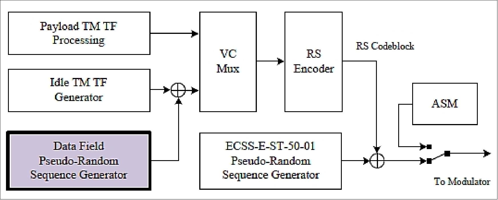
Comparison with Draft CCSDS SDLS Recommended Standard:
The first CCSDS SDLS protocol draft recommended standard (Ref. 34) was issued in February 2012. It aims at providing a common generic framework for TC, TM and AOS (Advanced Orbiting System) links, by defining additional protocol data unit fields and services. As opposed to it, the SEOSat implementation is ad-hoc and aims at inserting a low-overhead and low-impact Security Layer on the applicable standard protocol stack, and on the on-going system design. Both solutions place the Security Layer at the Transfer Sublayer, with some differences in the TF formats and security processing (encryption/authentication) which are shown in Figure 20.
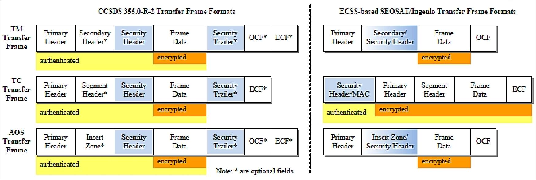
The CCSDS recommendation defines a common fixed-length Security Header (2-64 octets) and Security Trailer (8-64 octets), which are inserted around the Data Field. The Security Trailer includes just the MAC ( Message Authentication Code), and is optional. For TM TFs, SEOSAT's Security Layer uses the existing Secondary Header and Insert Zone fields in the ECSS and AOS standard TFs, respectively, for inserting (by overwriting specific octets) the Security Header. This solution avoids any overhead and allows keeping the TM TF format generated by the OBC and PDHU. It must be noted that the ECF (Error Control Field) is not used; otherwise it would need to be updated accordingly. The whole TF is error protected by the RS channel encoding (code (255,223) for TM and (255,239) for AOS). SEOSAT does not implement the TM TF authentication, whereas the CCSDS recommendation is to implement authenticated encryption.
Sensor Complement
PP (Primary Payload)
The prime contract for the PP instrument was awarded to Sener Ingeniería y Sistemas S. A. (Spain) in November 2008. The primary payload is a pushbroom imager composed of an optical panchromatic (PAN) and multispectral (MS) imaging detector in VNIR (Visible Near Infrared). SENER is the prime contractor for the PP (Primary Payload). The PP industrial consortium is integrated as well by Thales Alenia Space-España, it is responsible for the electronics, and INTA is responsible for the instrument AIV (Assembly, Integration and Verification) activities and for the optical support studies, including the straylight analysis. 36) 37)
PP is based on the following configuration: 38)
• A PAN channel
• Four MS bands in red, green, blue and near-infrared (NIR)
• The GSD corresponds to 2.5 m for the PAN band and 10 m for the MS bands.
• The swath width is ~55 km min (60 km x 60 km image cut) ensuring a repeat cycle of 38 days and a target accessibility of < 3 days on a global scale.
The main driver specification has been the FOV (Field of View). The instrument has a minimum linear swath specified of 55 km, that ensures a frequent revisit period. In addition, there is an emergency mode, providing quick accessibility to any point on Earth by viewing roll angles up to ±35º.
The optical quality has been specified at PP level, before post-processing. The minimum value required for the MTF (Modular Transfer Function) figure of merit is 0.115 for the PAN channel, and 0.3 for the MS channels, at their Nyquist frequencies. This relatively high MTF requirement is a mayor driving requirement of the instrument, and in fact, the most dimensioning parameter to resolve the EP (Entrance Pupil) diameter of the instrument. The maximum distortion required is 2% at the edge of the FOV.
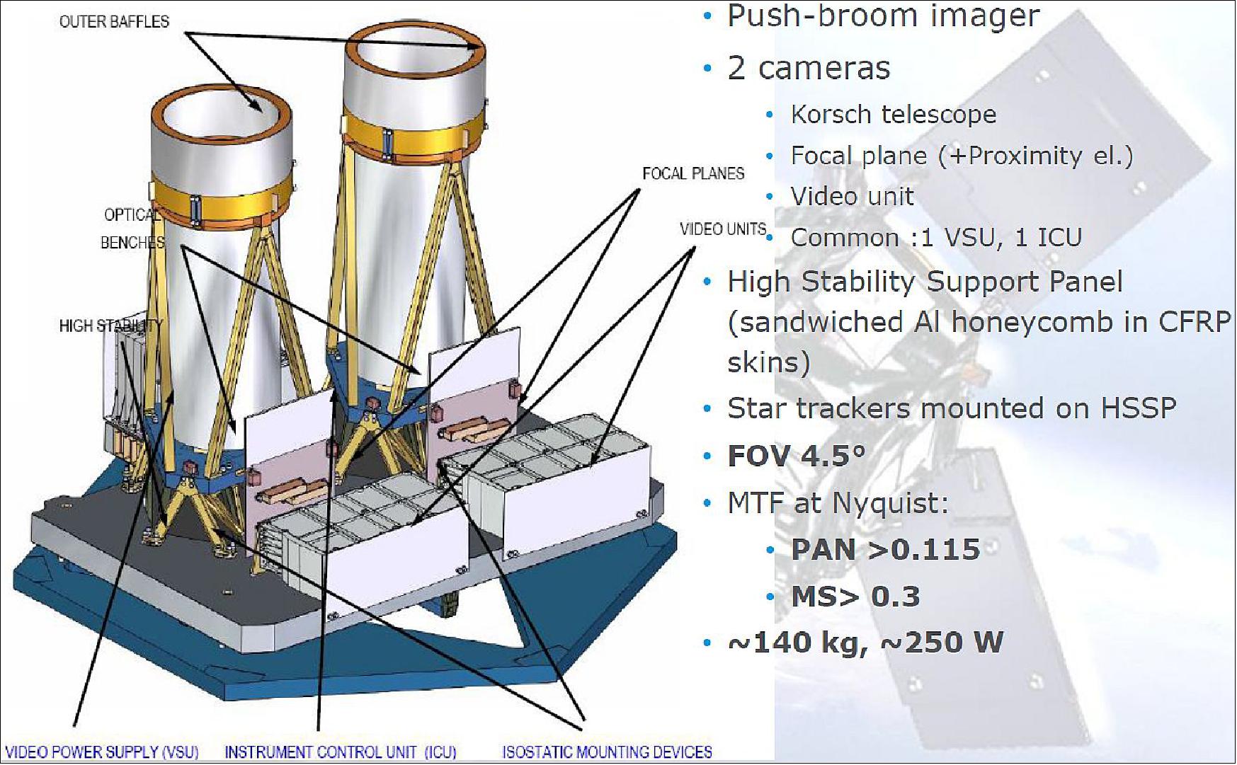
The PP concept is composed of two identical cameras (barrel-mounted), each one covering half of the specified PP swath. The instrument works in pushbroom mode, covering a swath of some 28km in both PAN and MS channels, acquiring images simultaneously, and building the overall instrument swath of 55 km. This leads to a FOV for each camera slightly below 3º. There is a small overlap between the cameras in order to guarantee the full coverage and post processing capabilities, the total FOV of the instrument is ~ 4.75º. The pupil size of each camera is circa 260 mm and the focal length some 3.57m, providing an f/13.7.
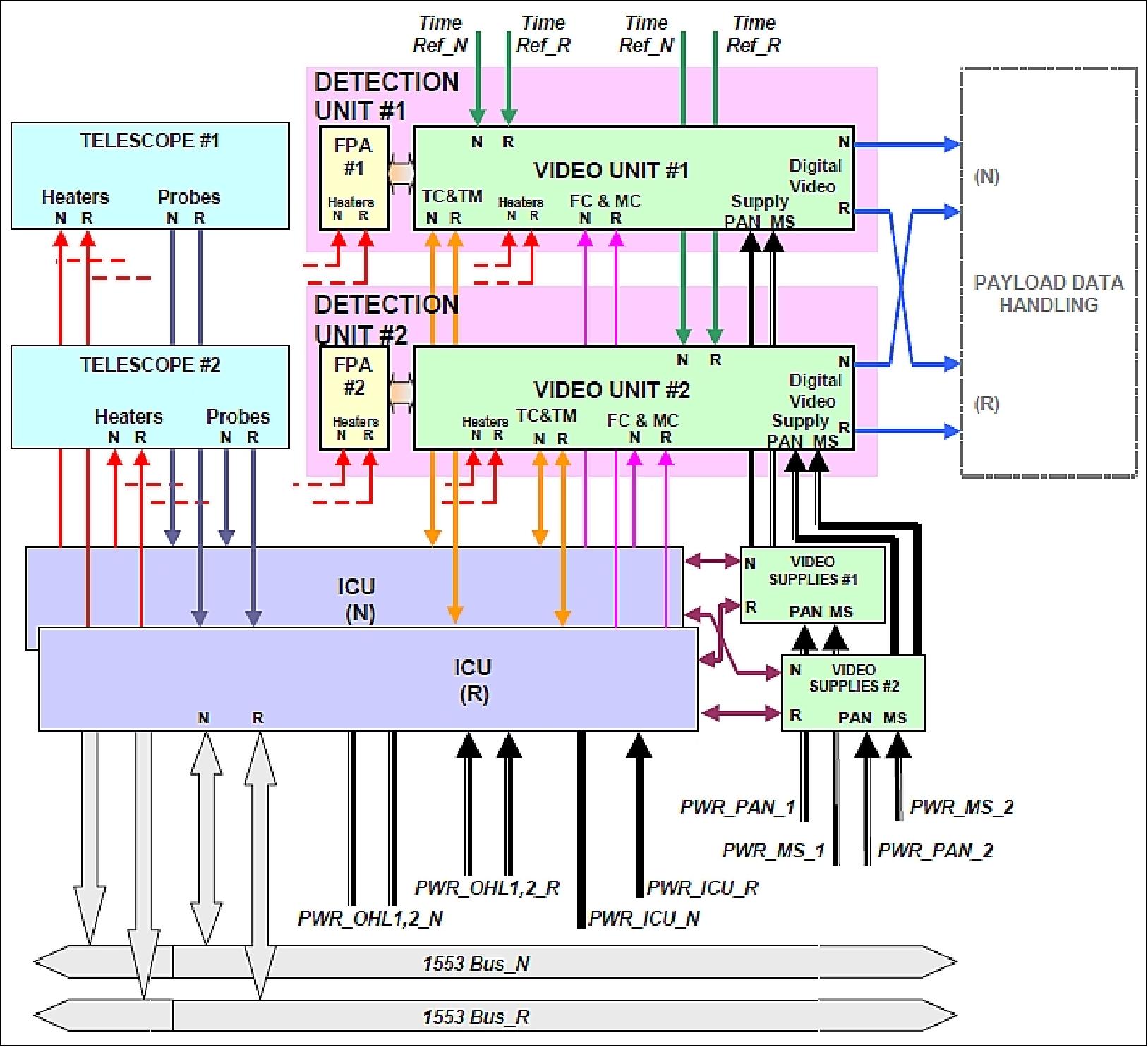
Each camera is composed of a Korsch-type TMA telescope (Figure 21), with its optical elements and baffles, a focal plane, including the sensing devices and filters, an electronics chain, two thermal refocusing devices integrated in M2, for a system refocusing on orbit, and a thermal control subsystem. The PP has therefore two telescopes, two focal planes, two electronic chains, two thermal refocusing devices and a thermal control box, all assembled together in high stability structure which provide the necessary thermoelastic performances and stiffness.
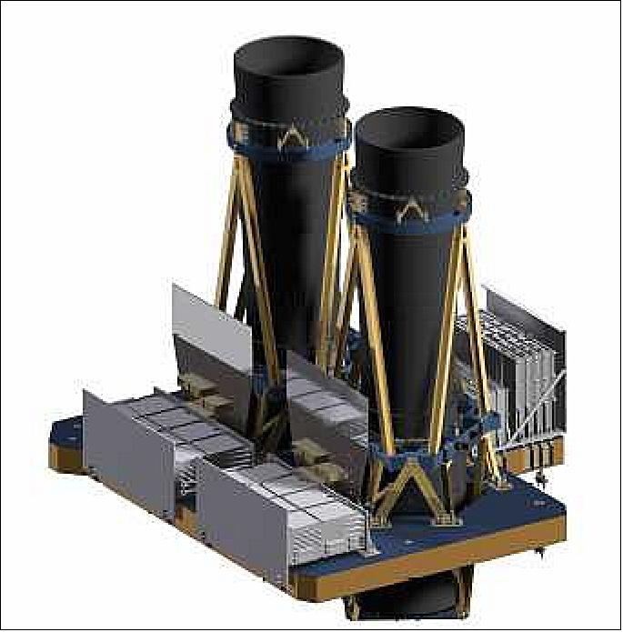
Each FPA (Focal Plane Assembly) includes a coplanar image plane, where four detectors are fitted. Two of them are PAN detectors, and the other two are MS detectors.
The PAN detectors have 6000 pixels with a pixel pitch of 13 µm and an integration time of 0.366 ms. The TDI (Time Delay and Integration) operating concept is implemented with a tunable number of stages to improve the SNR (Signal-to-Noise Ratio). The MS detectors have 1500 pixels with a pixel size of 52 µm and an integration time of 1.464 ms; they are composed of four linear arrays, each one corresponding to one spectral band: Blue, Green, Red and NIR.
The two cameras are identical, and are fully decoupled functionally, mechanically, thermally and electromagnetically in order to achieve full qualification of the overall Primary Payload , assemble with a single EQM (Engineering Qualification Model) of one camera and a structural dummy of the other.
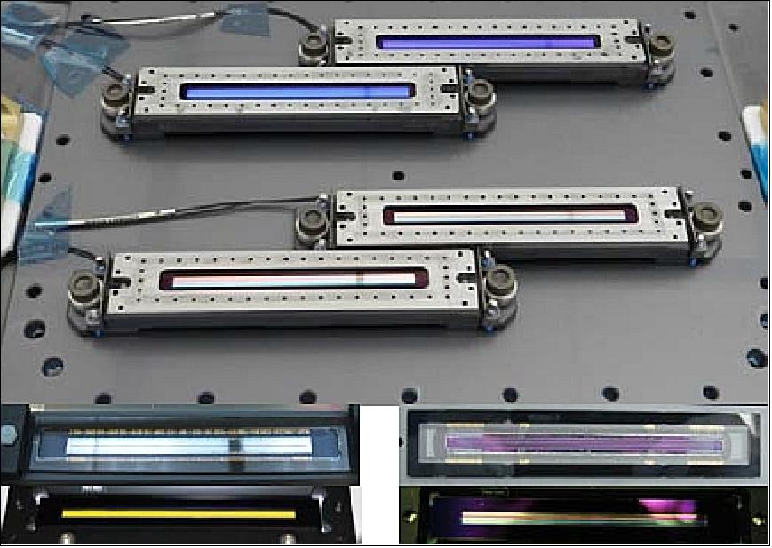
The detectors, manufactured by E2V, have large pixel's size which implies large focal planes, but they guarantee high values for SNR and MTF, two of the most restringing specifications.
Optical design: The Korsch optical system uses three powered anastigmatic mirrors plus one flat FM (Folding Mirror) used to extract the focal plane and to compact the whole structure. It works on-axis in pupil and field. This design embodies a large Cassegrain focal field and a comparatively small EP (Entrance Pupil).
Some significant benefits of this telescope design are:
• Capability of operating with focal planes of large dimensions.
• Efficient and compact stray-light baffling, due to the presence of an intermediate image, and the possibility of placing a Lyot stop at the EP of the system, which in this design lies close to the FM.
• Pure catoptrical system (but for the marginal effect of filter and detector windows), and hence free of chromatic aberrations, which was a priori a serious concern given the large spectral ranges of operation of the instrument. Also, the instrument will not suffer typical glass ageing effects due to incoming gamma-ray radiation.
• On-axis M3 (tertiary mirror), in contrast to other solutions based on the canonic Korsch design. This feature provides noticeable advantages in terms of lower manufacturing and alignment complexities. Also, it enables the use of a small FM without central hole.
• Focal length of the primary-secondary group of mirrors close to the effective focal length of the complete system. This enables the use of a M3 with magnification close to unity, making this element relatively tolerant to misalignment.
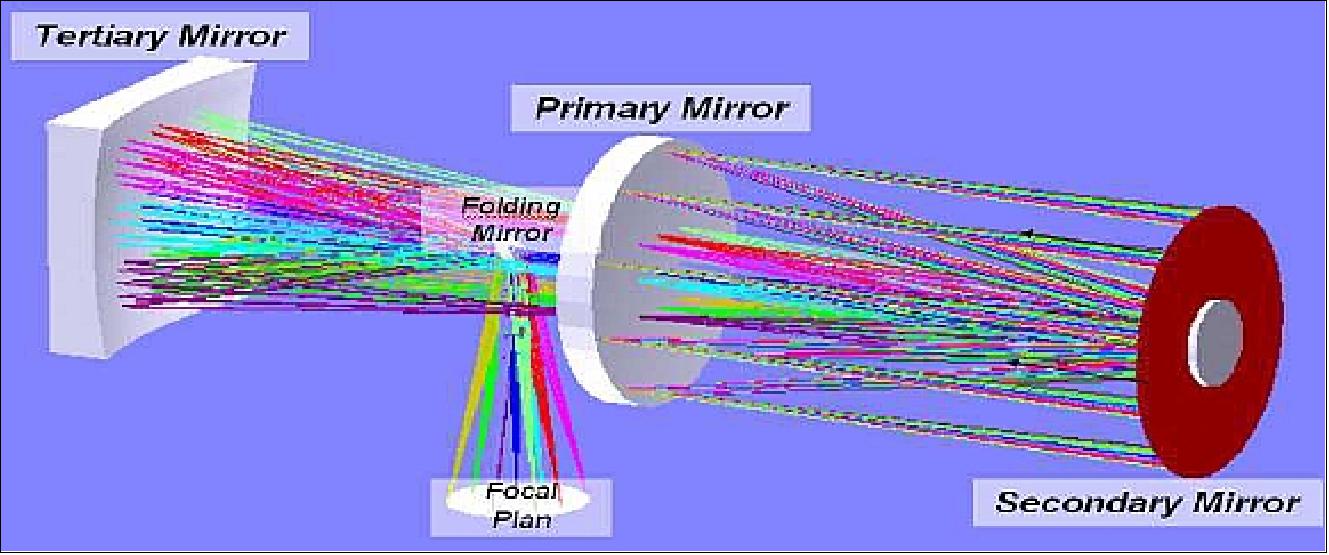
The system is designed with four all-reflective mirrors, enabling a spanning from blue to near infrared without chromatic aberration. M1 is the primary concave aspheric mirror. M2 is the secondary aspheric and convex mirror. M1 & M2 is a stigmatic telescope at the center of field. M3 is the tertiary and concave mirror, a field corrector. MF is the folding mirror.
• The primary mirror (M1) is the aperture stop of the telescope, and its diameter (260 mm) was derived from SNR and MTF specifications to optimize the optical system. This allows the reduction of diffraction effects and maximizes the SNR of the telescope.
• The secondary mirror (M2) is a hyperbolic Cassegrain's conjugate of the nearly parabolic M1. It creates an intermediate image at a plane slightly inside M1 mirror. This naturally creates a field diaphragm when machining a hole in M1 to allow light passage, which is commonly smaller than the M2 obscuration. The huge FOV for a Korsch design (about 3º for each telescope) makes that in SEOSAT/Ingenio design, image forming light beams exceed the M2 obscuration, forcing to machine four holes (slots) into M1 to allow the light passage. These slots complicated the straylight control, and provide SEOSAT/Ingenio with a particular look.
• The tertiary mirror (M3) is a field corrector with a magnification close to 1, which re-images the intermediate image in the focal plane after the deviation of the light beam in the FM. The unusual large size of this mirror is due to the large focal plane (and FOV) of the telescope. The FM is placed close to the EP of the system to minimize the FM size and obscuration, allowing the access to the Lyot stop in the EP itself. This Lyot stop plays a crucial role in the straylight control.
SAGEM-REOSC (France) has been awarded a contract by SENER to manufacture and test the component mirrors of the PP twin telescopes. The project involved manufacturing challenges to meet surface quality, light-weighting and vibration load requirements (lightweighting up to 72% with random acceleration up to 88.1g). SAGEM applied enhanced manufacturing technologies for the implementation of the mirror assemblies.
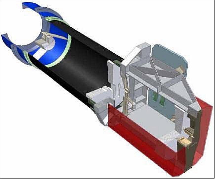
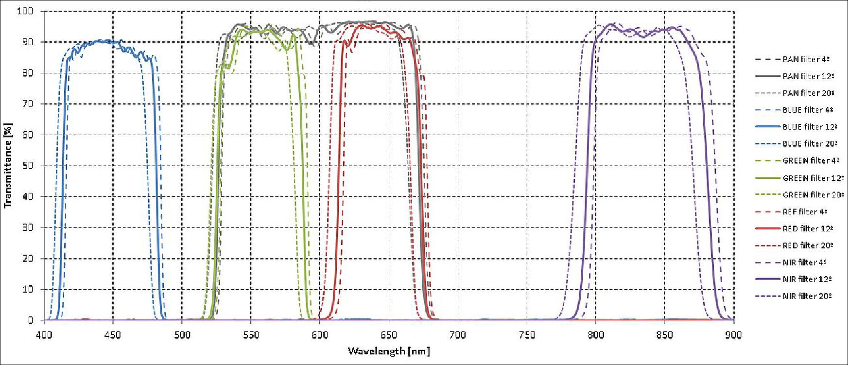
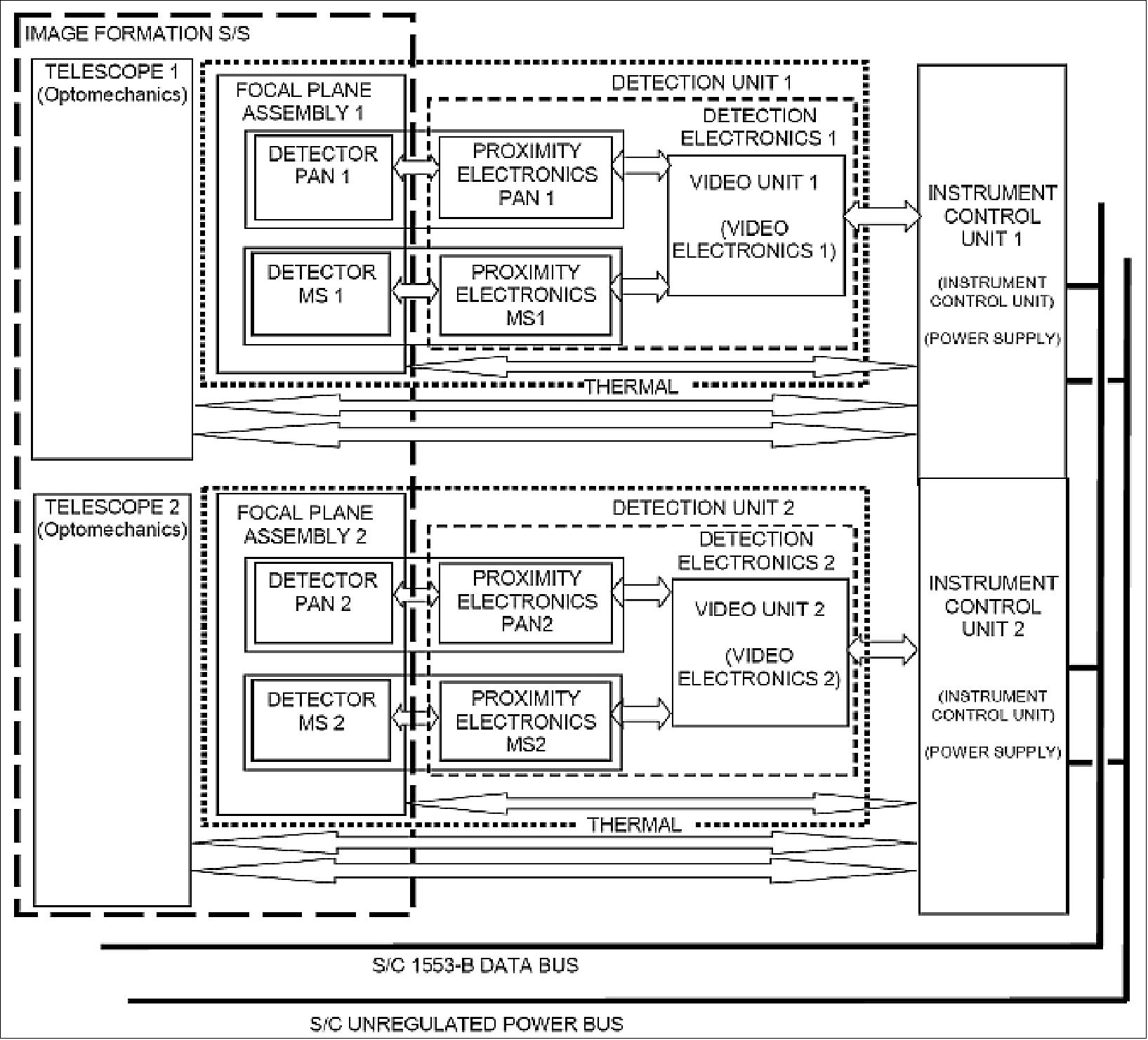
Parameter | PAN band | MS bands |
Spectral bands | 450-900 nm | 450-520 nm, 520-600 nm, 630-690 nm, 760-900 nm |
GSD (Ground Sample Distance) | 2.5 m | 10 m |
Swath | 2 x 28 km | 2 x 28 km |
FOV (Field of View) | 2º x 2.539º | 2º x 2.539º |
Detectors | E2V CCD98-50 | E2V AT71554 |
Focal length | 3520 mm | 3520 mm |
Pupil diameter | 220 mm | 220 mm |
F/number | 16 | 16 |
TDI (Time Delay Integration) | up to 20 TDI stages in any of five preset TDI lengths (7, 10, 13, 16, 20) |
|
CSP (Complementary Scientific Payload)
The CSP consists of three small and medium size instruments:
• SENSOSOL (Sensor solar de última generación que determina la posición del Sol para la orientación del satélite - A new generation solar sensor for getting the satellite orientation with respect to the Sun position). SENSOSOL has been developed by the University of Sevilla and the UPC (Universitat Politècnica de Cataluña), Barcelona, Spain. INTA has performed the space qualification on the NanoSat-1B mission. 39)
• TTT (The Two Towers) of INTA: An in-orbit dosimeter and radiation spectrometer hosting different sensors (solid-state).
• UVAS (Ultraviolet Visible and near infrared Atmospheric Sounder), PI: Alfonso Saiz-Lopezof CSIC (Consejo Superior de Investigaciones Cientificas) or the Spanish National Research Council, located in Madrid. UVAS is a CCD-based grating spectrometer of CSIC (Consejo Superior de Investigaciones Cientificas). The objectives of the UVAS instrument are to observe atmospheric profiles.

March 5, 2020: According to Carlos Castaño Climent of CDTI, the instruments TTT and UVAS are not going to be onboard SEOSAT/Ingenio mission. Their developments have been discontinued by their respective responsible entities. Only SENSOSOL will be embarked on SEOSAT/Ingenio, taking advantage of the opportunity offered by CDTI to fly CSP (Complementary Scientific Payloads) onboard SEOSAT/Ingenio. 40)
UVAS (Ultraviolet Visible and near infrared Atmospheric Sounder)
UVAS is conceived to gather global high spatial resolution maps of columns of density of trace gases and aerosols related to air quality and climate change. The instrument focuses on the processes that link atmospheric composition, sources and climate. These processes are of fundamental relevance, and it is important that the key components of the coupled Earth-atmosphere system be further understood, so that uncertainty in prediction of future climate scenarios can be minimized. It is equally important to provide platforms that measure the budgets of gases from anthropogenic emissions into the atmosphere in order to monitor compliance with international agreements. The fundamental objective of the mission is the measurement of atmospheric composition, with high precision and covering the whole height of the atmosphere, to study the feedback between the main anthropogenic gases, their sources, formation and loss mechanisms, and the Earth's climate processes. 41)
The main scientific objectives of the UVAS mission are:
1) Observe with unprecedented high spatial resolution the concentration of air quality monitoring gases including ozone (O3, nitrogen dioxide (NO2), sulphur dioxide (SO2), formaldehyde (HCHO) and glyoxal (CHO-CHO) and aerosols over selected urban areas.
2) Combine high spatial resolution observations with atmospheric models to better quantify sources and sinks of specific gases.
3) Assimilate the remote sensing measurements into global chemistry-climate models to examine the processes linking atmospheric composition and climate.
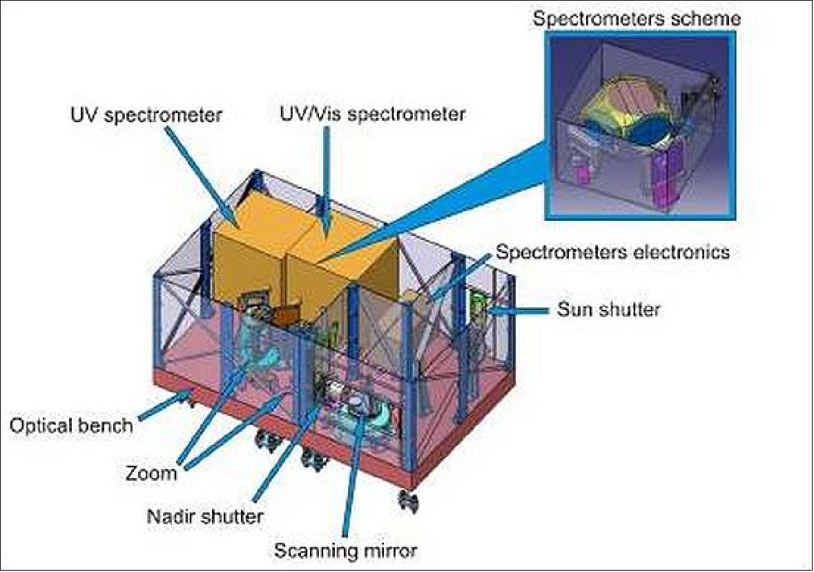
UVAS instrument: UVAS is a whiskbroom high-resolution spectrometer with two optical modules for its spectral range: 290-490 nm (UV/VIS). These modules are single-point spectrometers (i.e. with linear array sensors) that can be fed by either the calibration module or the Nadir pointing module.
The use of a whiskbroom system imposes some limits to the achievable SNR and swath, employing single-point spectrometers, but on the other hand, it minimizes the instrument budgets (envelope, mass and power) and simplifies the overall instrument design, especially the optical coupling between the instrument telescope and the imaging spectrometers.
The UVAS core consists of two miniaturized spectrometers modules for the Ultraviolet (290-390 nm), and Visible (390-490 nm) spectral ranges. The instrument is structured in the following modules:
• Optomechanical assembly (telescope assembly): comprising all mechanisms and optoelectronic elements that capture, guide and convert the input signal (light) to an electronic signal. This module can be further divided into:
- Two spectral modules (spectrometers) for the UV and VIS spectral ranges, including separated fore-optics, refractive, for optimal image formation and the spectrometer modules. These modules include the sensor arrays and the analog proximity electronics.
- Scanning mirror, to sequentially guide the light coming from different points within the field of view into the instrument. The scanning mirror provides the on-ground spatial resolution of the instrument.
- Nadir shutter, to protect the system from contamination, to perform dark current calibration and to protect the spectrometers and optics from large Sun pointing. The nadir shutter is open during target observations and closed for calibrations.
- Beam distribution module, to guide the beam into the instrument, depolarize the light and separate the suitable spectral bands for each spectral module.
- Calibration module, comprising a shutter for the Sun port, calibration LEDs and lamps, a diffuser and image-forming optics.
- Thermal elements, to provide the adequate thermal environment.

• Electronic assembly: to provide power conditioning, data processing, optomechanical control and the general instrument management.
• Intra-instrument harness for the interconnection of these assemblies.
Perpendicular to scan on ground pixel | 2500 m |
Scan direction on ground pixel | 2500 m |
Angle between scanning direction and cross-track direction | -30º |
Distance between two successive swaths (along-track direction) | 2887 m |
Number of projections of the slit integrated in one pixel | 5 bands in pixel |
Width on Earth of the projection of the slit (scan direction) | 500 m |
Number of pixels in a swath (imposed) | 34 pixels |
FOR (Field of Regard) at each side of nadir direction in the scanning direction | 500 km |
Cross-track FOR at each side of nadir direction | 433 km |
Min swath on Earth in the scanning direction | 85 km |
Min swath on Earth in cross-track | 73 km |
Integration time per pixel (transition time 0.001 s) | 0.0098 s |
Most penalizing movement for fly-back (assuming 2 x swath) | 14.54º |
UVAS will fly on board the SEOSAT satellite oriented into the flight direction and will observe solar radiation back-scattered and reflected from Earth's atmosphere and surface in nadir-viewing (downward looking) geometry. The scanning mirror will scan a swath towards the Earth's surface perpendicularly to the satellite flight direction. The light will be directed through the beam distribution module into the spectrometers; their tasks are to process the light to finally deliver, by means of the system electronics and retrieval algorithms, the atmospheric trace gases concentrations.
In the nominal operations mode, UVAS will perform high spatial resolution measurements with an on-ground pixel size lower than 10 km x 10 km. This spatial resolution exceeds those of any current NASA or ESA instrument, and will be the main advantage and contribution of UVAS to the Atmospheric Remote Sensing field.
UVAS features three in-flight calibration modes:
- Sun calibration: Consists of the acquisition of the Sun spectrum through the Sun port. This operation will be performed at the beginning of a SEOSat orbit, just after exiting the eclipse zone. The calibration shall be used for the absolute radiometric calibration during flight, therefore the sun will be observed via sun port and a diffuser plate.
- Wavelength calibration: Will be performed by means of selected athermal, narrow band fiber-optic LED signals as provided by the UVAS calibration module. This operation will be performed while the Sun & nadir port shutters are closed (dark signal cycle) preferably during eclipse and daily before sun calibration.
- Dark current calibration: A dark signal will be used to check the spectrometer module background dark signal using the same approach as for the wavelength calibration (dark signal cycle) preferably during eclipse. This operation will be performed once per orbit, depending on instrument performances.
Scientific objectives and applications: The UVAS mission will focus on the processes that link atmospheric composition, sources and climate. These processes are of fundamental relevance, and it is important that the key components of the coupled Earth-atmosphere system be further understood, so that uncertainty in prediction of future climate scenarios can be minimized. It is equally important to provide platforms that measure the budgets of gases from anthropogenic emissions into the atmosphere in order to monitor compliance with international agreements. - The primary goal of the mission is the measurement of atmospheric composition to study the feedback between the main anthropogenic gases, their sources, formation and loss mechanisms, and the Earth's climate processes.
The UVAS scientific team comprises researchers from CSIC, INTA and several Spanish Universities, as well as researchers from international scientific institutions like the Harvard-Smithsonian Center for Astrophysics and NASA. The UVAS PI (Principal Investigator) is Alfonso Saiz-López of CSIC.
The UVAS industrial cluster is composed by: CSIC (PM; PA; QA; SE), INTA (thermal and optical designs), EMXYS (electronics, HW and SW), AVS (mechanisms) and AST (mechanical design).
UVAS instrument location and pointing direction on the spacecraft: It has an angle deviation of 30 degrees as a result of a need for the instrument to adapt to the shape and other instruments on the platform (UVAS is not a dedicated instrument but a secondary scientific payload, hence subject to adaptability and fulfillment with the satellite and prime instrument and mission requirements). This angle deviation is known and approved by ESA and CDTI and the only implication is a change in the shape of the on-ground pixel, which is accounted for by on-ground software processing, but has NO effect at all on the instrument performance and/or scientific objectives of UVAS.
Ground Segment
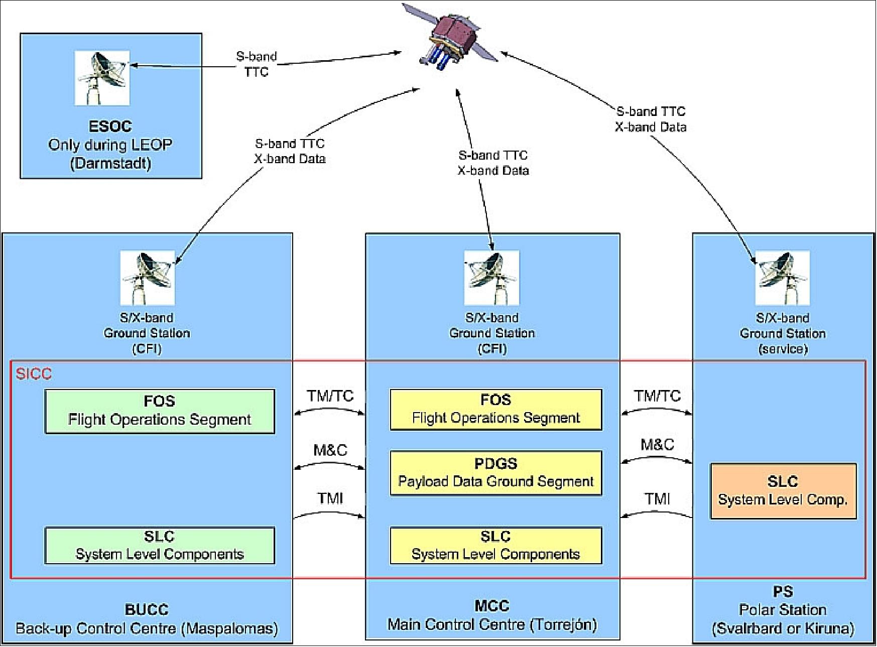
The Ingenio ground segment will be in Spain for the payload data acquisition, processing and dissemination to the users' community of the Ingenio products. Indra Systemas S.A. is the prime contractor of the Ingenio and the PAZ ground segment with contracts from INTA (PAZ) and ESA (Ingenio) to enable maximum commonality. 42) 43)
The ground segment is composed of two main elements: Ref. 5), and 7).
4) FOS (Flight Operation System), responsible for spacecraft control, spacecraft health monitoring, orbit control and on-board software configuration and maintenance
- The SMCC (Spacecraft Mission Control Center) is located in Torrejón de Ardoz near Madrid. The SMCC includes the nominal FOS and PDGS, a X-band downlink station and a S-band TT&C station.
- The SBUCC (Spacecraft Backup Control Center) is located in Maspalomas on the Canary Islands serving also as a complementary X-band acquisition station.
- In addition, the ground segment will receive data from polar acquisition stations to improve the daily coverage of the system.
5) PDGS (Payload Data Ground Segment), responsible for optical, science and ancillary data acquisition, processing, archiving and distribution, as well as mission planning. The temporary archive will be in Maspalomas, while the processing and long-term archive will be located in Torrejón.
References
1) Mónica López, "Spanish Earth Observation Program," URL: http://www.cdti.es/recursos/doc/Programas/Aeronautica_espacio_retornos_industriales
/Agencia_Espacial_Europea/1245_251125112008103422.pdf
2) J. Lomba, R. Trigo, J. Ureña, E. Vez, M. López, F. Cerezo, M. Fernández, A. Borges, J. Sánchez-Palma, "The Spanish Earth Observation Program," Proceedings of the 2nd Workshop on Advanced RF Sensors and Remote Sensing Instruments 2009, Noordwijk, The Netherlands, Nov. 17-18, 2009
3) Juan Urena, "SEOSAT: The Spanish Earth Observation Mission," SEOSAT – 1st Ground Segment Coordination Body Workshop, June 20, 2007, ESA/ESRIN, Frascati, Italy, URL: http://earth.esa.int/gscb/papers/19_Urena.pdf
4) "ESA To Oversee Development of Spanish Observation Sat," Space News, Oct. 9, 2006, p. 8
5) Jorge Lomba Ferreras, Mónica López, Juan Ureña Carazo, Emilio Vez Rodríguez, Roberto Trigo, Ana Isabel Neira Tapiador, "Future Spanish Earth Observation Satellite System," Proceedings of the 59th IAC (International Astronautical Congress), Glasgow, Scotland, UK, Sept. 29 to Oct. 3, 2008, IAC-08-B1.2
6) Eva Vega, Juan Ureña, "Ingenio and PAZ Ground Segment Interoperability ProgramaNacional de Observaciónde la Tierra porSatélite-PNOTS (Spanish Earth Observation Satellite Programme)," GSCB (Ground Segment Coordination Body) Workshop, ESA/ESRIN, Frascati, Italy, June 18-19, 2009, URL: http://www.congrex.nl/08c33/papers/4.6_Urena.pdf
7) Eva Vega, Juan Ureña, "Ingenio and PAZ Ground Segment Interoperability," GSCB (Ground Segment Coordination Body) Workshop, June 18-19, 2009, ESA/ESRIN Frascati, Italy, URL: http://earth.esa.int/gscb/papers/4.6_Urena.pdf
8) "SEOSat/Ingenio," Astrium CASA Espacio, URL: https://web.archive.org/web/20160317215021/http://www.casaespacio.com/sites/default/files/SEOSAT_INGENIO.pdf
9) A. López, A. Pizarro, H. Marcille,Y. Lecureux, J. P. Lejault, "A High Performance Gyroless AOCS for SEOSAT/INGENIO," Proceedings of GNC 2011, 8th International ESA Conference on Guidance, Navigation & Control Systems, Carlsbad, Czech Republic, June 5-10, 2011
10) "SEOSAT / Ingenio Industry day," Nov. 17, 2008, EADS CASA Espacio, URL: http://www.cdti.es/recursos/doc/Programas/Aeronautica_espacio_retornos_industriales
/Agencia_Espacial_Europea/36426_25112511200810372.pdf
11) "Thales Alenia Space España delivers first X-band images communication system of the first Spanish Earth observation satellite," June 12, 2012, URL: https://web.archive.org/web/20160322092342/https://www.thalesgroup.com/en/content/thales-alenia-space-espana-delivers-first-x-band-images-communication-system-first-spanish
12) "An ingenious dress rehearsal," ESA Enabling & Support, 16 November 2020, URL: https://www.esa.int/ESA_Multimedia/Images/2020/11/An_ingenious_dress_rehearsal
13) "SEOSAT-Ingenio sealed from view," ESA Applications, 10 November 2020, URL: https://www.esa.int/Applications/Observing_the_Earth
/SEOSAT-Ingenio/SEOSAT-Ingenio_sealed_from_view
14) "SEOSAT-Ingenio: fully loaded," ESA Applications, 22 October 2020, URL: https://www.esa.int/Applications/Observing_the_Earth/SEOSAT-Ingenio/SEOSAT-Ingenio_fully_loaded
15) "SEOSAT-Ingenio team in Kourou after countdown rehearsal," ESA Applications, 12 October 2020, URL: https://www.esa.int/About_Us/Week_in_images/Week_in_images_12-16_October_2020
16) "SEOSAT-Ingenio arrives in French Guiana," ESA Applications, 25 September 2020, URL: https://www.esa.int/Applications/Observing_the_Earth/
SEOSAT-Ingenio/SEOSAT-Ingenio_arrives_in_French_Guiana
17) "SEOSAT-Ingenio soon to be launched," ESA Applications, 22 September 2020, URL: https://www.esa.int/ESA_Multimedia/Videos/2020/06/SEOSAT-Ingenio_soon_to_be_launched
18) "SEOSAT-Ingenio being prepared for shipment to Kourou," ESA Applications, 14 July 2020, URL: https://www.esa.int/About_Us/Week_in_images/Week_in_images_20-24_July_2020
19) "SEOSAT-Ingenio ready for shipment to Kourou," ESA / Applications / Observing the Earth, 15 June 2020, URL: http://www.esa.int/Applications/Observing_the_Earth
/SEOSAT-Ingenio_ready_for_shipment_to_Kourou
20) Information provided by Carlos Castaño Climent, head of the SEOSAT Program at CDTI
21) Airbus built SEOSAT/Ingenio is finished and ready for testing," Airbus Press Release, 18 June 2019, URL: https://web.archive.org/web/20210122100631/https://www.airbus.com/newsroom/press-releases/en/2019/06/airbus-built-seosatingenio-is-finished-and-ready-for-testing.html
22) "SEOSAT in the cleanroom," ESA, 5 June 2019, URL: https://www.esa.int/spaceinimages/Images/2019/05/SEOSAT_in_the_cleanroom
23) "Arianespace – Flight Vega VV17 – SEOSAT-Ingenio / TARANIS: Mission failure," Arianespace Press Release, 16 November 2020, URL: https://www.arianespace.com/press-release
/arianespace-flight-vega-vv17-seosat-ingenio-taranis-mission-failure/
24) "Nº 23–2020: Vega flight VV17 failure: Arianespace and ESA appoint an independent Inquiry Commission," ESA Press Release Nº 23-2020, 17 November 2020, URL: https://www.esa.int/Newsroom/Press_Releases/
Vega_flight_VV17_failure_Arianespace_and_ESA_appoint_an_independent_Inquiry_Commission
25) "Loss of Vega Flight VV17: Independent Enquiry Commission announces conclusions," Arianespace Press Release, 18 December 2020, URL: https://www.arianespace.com/press-release/
loss-of-vega-flight-vv17-independent-enquiry-commission-announces-conclusions/
26) Ignacio Herrera Alzu, Francisco Perán Mazón, Juan Andrés Sanz Cuesta, Ignacio Aguilar Sánchez, "SEOSat/Ingenio Security System," Proceedings of TTC 2013, 6th International Workshop on Tracking Telemetry and Command Systems for Space Applications, Darmstadt, Germany, Sept. 10-13, 2013
27) I. Aguilar Sánchez, D. Fischer, "The CCSDS Space Data Link Security Protocol," Proceedings of TTC 2013, 6th International Workshop on Tracking Telemetry and Command Systems for Space Applications, Darmstadt, Germany, Sept. 10-13, 2013
28) "CCSDS Cryptographic Algorithms," Recommended Standard CCSDS 352.0-B-1, Blue Book, November 2012
29) "Space Data Links – Telecommand Protocols, Synchronization and Channel Coding," ECSS-E-50-04C, July 2008
30) "Space Data Links – Telemetry Transfer Frame Protocol," ECSS-E-50-03C, July 2008
31) "AOS Space Data Link Protocol," Recommended Standard CCSDS 732.0-B-2, Blue Book, July 2003
32) "Space Data Links – Telemetry Synchronization and Channel Coding," ECSS-E-50-01C, July 2008
33) I. Aguilar Sanchez, G. Moury, C. Biggerstaff, B. Saba, D. Fischer, H. Weiss, "Towards Completion of the CCSDS Space Data Link Security Protocol", Proceedings of the IEEE Aerospace Conference, Big Sky, MT, USA, March 3-10, 2012
34) "CCSDS Space Data Link Security Protocol," Draft Recommended Standard CCSDS 355.0-R-2, Red Book, Feb. 2012
35) R. Garello, M. Baldi, F. Chiaraluce, "Randomizer for High Data Rates", ESOC Contact. No. 20959/07/D/MRP, Politecnico di Torino, 2009
36) L. Pascual, JI. Bueno, D. Zorita, C. Miravet, G. Taubmann, A. García Marín, I. Monasterio,C. Mas, J. Azcona, JM. Arroyo, U. García Feijoo, R. López, R. Martínez Casado, J. de Miguel, J. Eguía, S. Jarabo, N. Macías, T. Belenguer, LM González, I. Cabeza, A. Marini, G. Crippa, "Detailed Optical Design of SEOSAT/Ingenio Spanish High Resolution Imaging Instrument," Proceedings of the ICSO (International Conference on Space Optics), Ajaccio, Corse, France, Oct. 9-12, 2012, paper: 051, URL: http://congrex.nl/icso/2012/papers/FP_ICSO-012.pdf
37) Emmanuelle Harel, "Light-weighting, Polishing and Bonding for the SEOSAT/Ingenio Telescope Mirrors," Proceedings of the ICSO (International Conference on Space Optics), Ajaccio, Corse, France, Oct. 9-12, 2012, paper: ICSO-012, URL: http://congrex.nl/icso/2012/papers/FP_ICSO-012.pdf
38) "SEOSat/Ingenio Industrial Day Primary Payload," Nov. 17, 2008, Madrid, Spain, URL: http://www.cdti.es/recursos/doc/Programas/Aeronautica_espacio_retornos_industriales
/Agencia_Espacial_Europea/36426_25112511200810372.pdf, and URL: http://www.cdti.es/recursos/doc/Programas/Aeronautica_espacio_retornos_industriales
/Agencia_Espacial_Europea/44776_251125112008103852.pdf
39) F. J. Delgado, J. M. Quero, J. Garcia, C. L. Tarrida, "SENSOSOL: MultiFOV 4-Quadrant high precision sun sensor for satellite attitude control," Spanish Conference on Electron Devices (CDE), Valladolid, Spain, Fe. 12-14, 2013, IEEE, DOI: 10.1109/CDE.2013.6481358
40) Information provided by Carlos Castaño Climent of CDTI, Madrid, Spain
41) Information provided by Alfonso Saiz-Lopez of CSIC, Madrid, Spain.
42) Daniel Carrasco, Victoriano Moreno, Emilio Viedma"Ingenio and Paz Ground Segments," 3rd GSCB (Ground System Coordination Body) Workshop, ESA/ESRIN, Frascati, Italy, June 6-7, 2012
43) "Indra leads the development and implementation of the Ingenio Ground Segment," Sept. 27, 2012, URL: http://www.indracompany.com/en/noticia/
indra-leads-the-development-and-implementation-of-the-ingenio-ground-segment
The information compiled and edited in this article was provided by Herbert J. Kramer from his documentation of: "Observation of the Earth and Its Environment: Survey of Missions and Sensors" (Springer Verlag) as well as many other sources after the publication of the 4th edition in 2002. - Comments and corrections to this article are always welcome for further updates (eoportal@symbios.space).
Spacecraft Launch Sensor Complement Ground Segment References Back to Top