LLITED (Low-Latitude Ionosphere/Thermosphere Enhancements in Density)
EO
Atmosphere
Atmospheric Temperature Fields
NASA
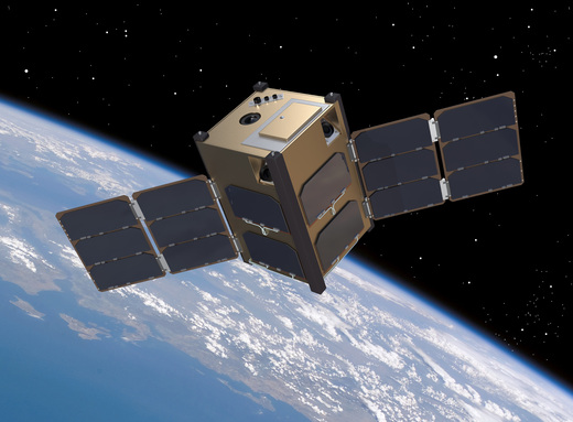
LLITED (Low-Latitude Ionosphere/Thermosphere Enhancements in Density) is a NASA CubeSat mission to provide data for the Equatorial Ionisation Anomaly (EIA) and the Equatorial Temperature and Wind Anomaly (ETWA). Two LLITED 1.5U CubeSats were launched on 15 April, 2023 on board a SpaceX Transporter-7.
Quick facts
Overview
| Mission type | EO |
| Agency | NASA |
| Mission status | Operational (nominal) |
| Launch date | 15 Apr 2023 |
| Measurement domain | Atmosphere |
| Measurement category | Atmospheric Temperature Fields, Atmospheric Winds |
| Measurement detailed | Atmospheric stability index, Electron density profile, Wind stress |
| Instruments | GPS receiver |
| Instrument type | Other, Data collection, In situ |
| CEOS EO Handbook | See LLITED (Low-Latitude Ionosphere/Thermosphere Enhancements in Density) summary |
Summary
Mission Capabilities
LLITED will carry three main instruments: a miniature ionisation gauge space instrument (MIGSI), a planar ion probe (PIP), and a GPS radio occultation sensor (CTECS-A). MIGSI is used to measure very low pressures, while PIP is used to measure in-situ plasma density. CTECS-A provides position, navigation and timing (PNT) and can be used for either overhead or occulting observations.
Performance Specifications
MIGSI has a horizontal cell size capability of 400 m, PIP has a capability of 8 m, and CTECS-A has a vertical cell size capability of 1 km. MIGSI has a precision of 0.1% and an accuracy of 20%, while MIGSI and PIP both have a sampling rate of 1 Hz.
Space and Hardware Components
The LLITED bus structure is similar to AeroCube-7 but with four deployed solar panels instead of two due to the need to maximise power generation for operating the payloads. The first ground station based in California, USA has a 5 m diameter dish antenna at 914.7 MHz, with 30 dB gain, 5 degree beamwidth and uses a complementary radio with a 10 W amplifier. The second is a portable 2 m diameter dish which has 23 dB gain, a 12 degree beamwidth and also uses a complementary radio with a 10W amplifier.
Overview
LLITED (Low-Latitude Ionosphere/Thermosphere Enhancements in Density) is a NASA CubeSat mission. It is funded by a 3-year grant for two 1.5U CubeSats with a 1-year on-orbit mission life. Each CubeSat will host a miniature ionisation gauge space instrument (MIGSI), planar ion probe (PIP), and GPS radio occultation sensor (CTECS-A). The mission objective is to provide both ionosphere and thermosphere measurements related to the Equatorial Ionisation Anomaly (EIA) and the Equatorial Temperature and Wind Anomaly (ETWA). 1)
While the EIA has been extensively studied both observationally and with modelling, the ETWA is less well known since observations are infrequent due to a lack of suitably instrumented spacecraft at appropriate altitudes. The LLITED CubeSat mission proposes to provide both ionosphere and thermosphere measurements that will be used to characterise and improve our understanding of the ETWA, provide insight into the coupling physics between the ETWA and EIA, and increase our knowledge of the dusk side dynamics that may influence space weather. For the first time, coincident high-resolution measurements of the dusk side thermosphere/ionosphere at lower altitudes will be made, providing a detailed examination of the ETWA.
The mission will consist of two 1.5U (10 x 10 x 15 cm) CubeSats in a high-inclination circular orbit, with an orbit altitude between 350 and 450 km. The CubeSats will maintain a 1/4 to 1/2 orbit separation to each other in order to observe any temporal changes as the ETWA evolves. The products provided are in-situ neutral pressure/density, in-situ plasma density, and a measurement of the total number of electrons along the line-of-sight between the satellite and the receiver (slant TEC). The observations from LLITED will be combined with other available data, such as the remote sensing observations of the ICON (Ionospheric Connection Explorer) mission, to provide a comprehensive dataset of the ETWA.
Equatorial Temperature and Wind (ETWA) and Equatorial Ionisation Anomaly (EIA)
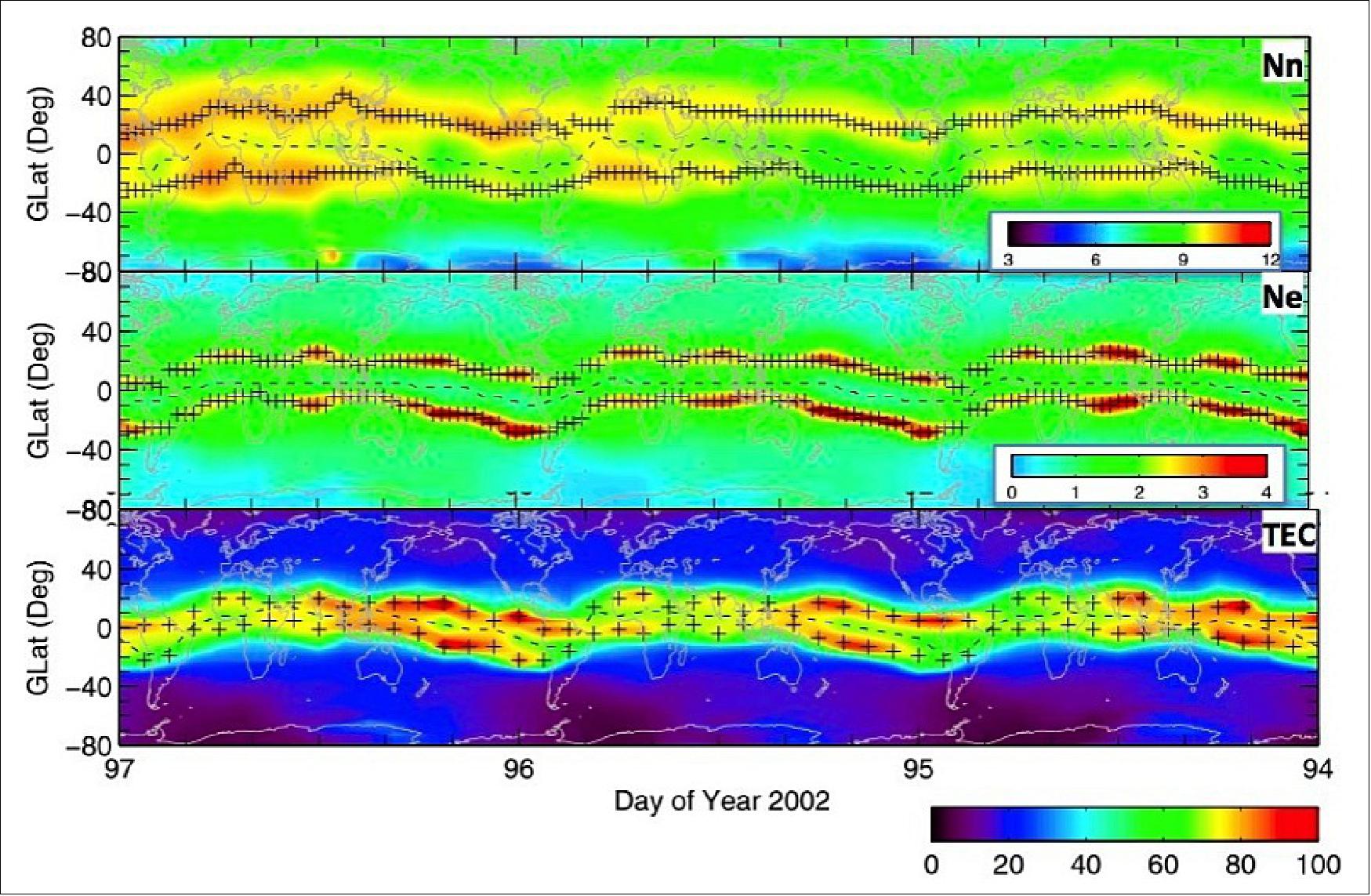
The low-latitude nighttime ionosphere-thermosphere (IT) region (100-500 km) contains large scale features and a host of phenomena including space weather driven events such as Equatorial Spread-F and scintillation. Two prominent features of the region are the Equatorial Ionisation Anomaly (EIA) and the Equatorial Temperature and Wind (ETWA), which occur to some extent in all longitudes within ±40° geographic latitude.
The EIA consists of regions of enhanced plasma density on either side of the equator and were first discovered by Namba and Maeda in their 1939 paper on Radio Wave Propagation (ref. 2). Over time, the EIA has been extensively studied using observations from a varied array of platforms ranging from ground-based ionosonde and GPS data, to on-orbit in-situ plasma sensors and remote sensing sensors such as Far Ultraviolet (FUV) imagers and GPS radio occultation. 2) 3) 4)
The formation of the EIA occurs when plasma at the equator is driven upward via the vertical ExB drift, and then diffuses to lower altitudes along geomagnetic field lines. This is also known as the “fountain effect”. The variability of the EIA, especially during geomagnetic activity, may provide conditions conducive to various space weather events.
The ETWA is identified by enhancements in the thermospheric neutral temperature and neutral densities that, while occurring at low latitudes, also occur at latitudes slightly higher than the EIA. Neutral density enhancements and troughs were originally observed using sensor data from the Orbiting Geophysical Observatory-6 (OGO-6) and Dynamic Explorer-2 (DE-2) satellite missions in the 1970s and 1980s. Unlike the EIA, the ETWA is less understood and observations are relatively scarce. 5)
Over the years, a number of studies have proposed mechanisms to explain the formation of the ETWA. The first hypothesis describing ETWA daytime formation involved variations in the zonal ion drag as a function of latitude. This variation results in energy flow from the dayside to the nightside being damped at EIA crest latitudes producing enhancements in neutral temperature and density. Another theory put forth by Fuller-Rowell et al. (ref. 7) speculated that the ETWA was the result of chemical heating from the exothermic recombination of O+.8 This theory was tested with model simulations with mixed success. The simulations were able to reproduce the vertical wind values coincident with DE-2 observations but were unable to explain the latitude separation or longitudinal variations between the EIA and ETWA phenomena. Other studies explained the appearance of daytime ETWA as the result of tidal coupling. None of the studies previously mentioned were able to fully describe the characteristics of the ETWA and its relationship to the EIA. 6) 7) 8) 9) 10)
Mission Objectives
While complete understanding of the formation of the ETWA and the coupling mechanisms between it and the EIA is the science community’s overall goal in studying these phenomena, it is not one that can be achieved with the currently available datasets. A comprehensive study requires a long-term database (greater than a year) of measurements that include neutral density, wind, and temperature, and plasma density and drift. However, progress can be achieved in understanding this compelling region including specific aspects of the ETWA and its coupling to the EIA.
The overall objective of LLITED is to improve our understanding of the relationship between the nightside EIA and ETWA. The specific science questions to be addressed are:
1) What is the mesoscale variability of the ETWA as a function of season, and longitude/latitude as well as its relationship to EIA heating?
2) What is the relationship between neutral winds (i.e., tides) and the EIA zonal structure?
3) Are small-scale wave fluctuations in neutral atmosphere quantities, such as those observed by earlier missions exhibited in the ionospheric density?
Spacecraft
The LLITED mission consists of two 1.5U CubeSats. The LLITED bus structure is similar to AeroCube-7 (launched in August 2016) but with four deployed solar panels instead of two. The subsystem electronics utilises the majority of AeroCube-10 designs with minor modifications (i.e. white wire corrections). The exception is a payload interface board as well as a high voltage daughter board that is designed specifically for LLITED. Each spacecraft will host the Miniature Ionization Gauge Space Instrument (MIGSI), Planar Ion Probe (PIP), and the Compact Total Electron Content Sensor – Aerospace (CTECS-A).
Figure 2 shows three different views of the current and nearly final CAD model. Adequate space is available for the bus subsystems and payloads as illustrated in panel A). Panel B) shows the spacecraft configuration as stowed in the P-pod launcher and immediately upon release. Panel C) illustrates the nominal operational configuration. In each of the panels, the top face contains the MIGSI and planar probe which will be directed into the RAM.
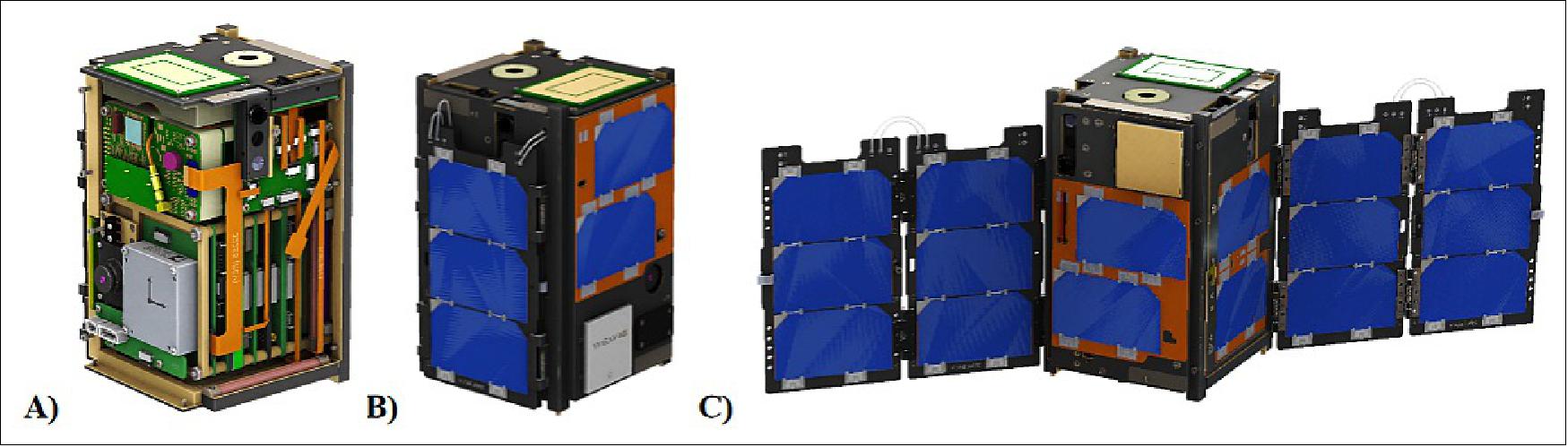
Because of the power required to operate the payloads, maximising power generation is a priority. This is achieved by utilising next generation high efficiency solar cells and bi-fold solar panels unlike previous missions. The solar panels are a completely new design and were considered one of the most high-risk aspects of the project. Thus, design work for the panels began early in the project.
Launch
Spaceflight Inc., the global launch services provider, announced on 22 March 2021 it has been awarded a launch service contract for the integration and launch of NASA’s LLITED mission, two 1.5U spacecraft. Spaceflight Inc. will transport the NASA Low-Latitude Ionosphere/Thermosphere Enhancements in Density (LLITED) CubeSats to low Earth orbit on its Sherpa-LTC orbital transfer vehicle (OTV) aboard a SpaceX Falcon 9. For this mission, the Sherpa-LTC, which uses chemical propulsion from Benchmark Space Systems, will make its initial spacecraft deployments and then ignite and manoeuvre to another orbital destination to deploy the NASA CubeSats. 11)
The LLITED mission is a grant awarded to The Aerospace Corporation through NASA’s Division of Heliophysics in the Science Mission Directorate and was selected for flight by the agency’s CubeSat Launch Initiative (CSLI). As a U.S. government direct procurement, Spaceflight is the prime contractor to NASA for the mission and the launch service is led by NASA’s Kennedy Space Center Launch Services Program. The LLITED team includes scientists and engineers from The Aerospace Corporation, Embry-Riddle Aeronautical University, and University of New Hampshire.
LLITED A and B were launched on April 15, 2023, aboard the SpaceX Transporter-7 rideshare mission from the Vandenberg Space Force Base.
Mission Status
- April 15, 2023: The LLITED A and B Cubesats were launched from Space Launch Complex 4E at the Vandenberg Space Force Base. The mission launched at 06:48 UTC. 15)
- November 7, 2022: Momentus (NASDAQ:MNTS) has signed a contract modification with NASA's Kennedy Space Center to provide orbital delivery services to transport two satellites to orbit for NASA's Low-Latitude Ionosphere and Thermosphere Enhancements in Density (LLITED) mission, which is targeted to launch in 2023.
- March 30, 2021: NASA’s plans to study changes in upper atmospheric densities, which affects the impact of the Earth’s atmosphere on satellites in low orbit, is getting closer to take-off. Launch services provider Spaceflight Inc. recently announced it has been awarded the contract for integration and launch of NASA’s Low-Latitude Ionosphere/Thermosphere Enhancements in Density (LLITED) mission, which features two 1.5U spacecrafts designed, built and operated by The Aerospace Corporation.
Sensor Complement
Each of the two 1.5U CubeSats will host a miniature ionisation gauge space instrument (MIGSI), planar ion probe (PIP), and GPS radio occultation sensor (CTECS-A). The Aerospace Corporation is providing the IG and CTECS-A sensors, while Embry-Riddle is providing the PIP. The products provided are in-situ neutral pressure/density, in-situ plasma density, and slant TEC. The observations from LLITED will be combined with other available data, such as the remote sensing observations of ICON, to provide a comprehensive and compelling dataset of the ETWA. Table 1 shows the sensor performance and their relation to the science mission requirements.
Parameter | Requirement | MIGSI | PIP | CTECS-A |
Scientific Measurement | Neutral Density, in-situ andBackground Plasma Density | Pressure (Neutral Density) | Ion Density | TEC (also Ne) |
Instrument Performance | Precision: 10% (Nn, Ne); 3TECU | 10-8 to 10-2 torr Precision: 0.1% Accuracy: 20% Sampling Rate: 1 Hz | 2x10⁹ to 2x10¹³ m-3 Sampling Rate 1Hz | 3-200 TECU r.m.s. = 3 TECU |
Heritage | --- | LAICE CubeSat | DICE CubeSat, WADISand MTeX rockets | Antenna: SENSE; Receiver: AC7-9 |
Current TRL |
| 4 | 6 | Antenna: 8, Receiver: 3 |
Horizontal Cell Size | 15 km | Capability: 400 m, Mission Op.: 1km | Capability: 8 m; Mission Op.: 1km | N/A |
Vertical Cell Size | N/A | N/A | N/A | ~1 km |
Attitude Requirements | As needed for sensors | Ram facing, 3-axis stable, 1º control, 0.1º knowledge | Ram facing, 3-axis stable, 10º control, 1º knowledge | Ram facing, 3-axis stable, 15º control |
Field of View | As needed for sensors | 180º | 180º | 180º |
Voltage | Bus supplies +5 or +12V | +12V & +5V | +5V | +5V |
Average Power | 2.73 to 3.5 W (Payloads only) | 3.57 W | 0.25 W | 1-1.3 W |
Mass | 0.6 kg | ~200 g | ~220 g | ~140 g |
Volume | 0.5 U | Board: ~10 x 9 x 1 cm Chamber: ~6 cm spherical | Board: ~10 x 10 x 1cm Plate: 5 x 6 x 0.5 cm | Receiver: ~10 x 10 x 1 cm Antenna: 7.6x 7.6 x 1.3 cm |
Duty Cycle | 60% of orbit coverage | 60% (2.14 W OAP) | 60% (0.15 W OAP) | 60% (0.78 W OAP) |
Data Rate | 115.2 kbit/s for each of four stations 2 contacts/day of minimum 3 min duration | Nominal: 256 bits/sec | 48 bits/sec | Variable: 1000-1778 bits/sec |
MIGSI (Miniature Ionisation Gauge Space Instrument)
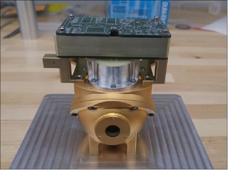
MIGSI consists of three components: a Bayard-Alpert sensor, an accommodation chamber, and a controller. The sensor operates by measuring the pressure inside the accommodation chamber. The MIGSI aperture must be located on the ram face of the spacecraft to admit incoming neutral gas. An additional requirement is that the spacecraft is 3-axis stabilised and that the alignment of the aperture with the velocity vector is within one degree. MIGSI is a modified design based on The Aerospace Corporation’s ionisation gauge (IGS) that flew successfully on the STREAK satellite mission. The ionisation gauge electronics has been adapted and delivered for a payload on the NSF LAICE CubeSat mission. For LLITED, the electronics have been split into two boards. Figure 8 shows the completed engineering unit. On top are the two electronics boards (double-sided populated). The silver cylinder in the centre is the ionisation gauge itself (filament and collector) and the bottom gold sphere is the accommodation chamber. 12)
MIGSI will operate similarly to the IGS flown on the STREAK mission. The amount of gas pumped into the sensor will be dependent on the vehicle velocity and orientation, and several parameters of the ambient gas. Using elementary gas kinetic theory and a set of simple assumptions, a fully general expression for the response of the instrument to the gas flow can be derived. The assumptions are: the amount of gas entering the chamber is the same as that leaving, the sensor is operating in a free-molecular flow regime, and the gas measured by the gauge has been completely accommodated to the temperature of the chamber walls.
PIP (Planar Ion Probe)
Langmuir probes have been routinely used on sounding rockets and satellites to measure in-situ plasma density. They can be implemented as fixed bias (DC) probes or can have their bias swept from negative to positive potential with respect to the spacecraft chassis ground. Swept bias probes provide absolute plasma density and electron temperature with every sweep, but require the spacecraft surface to probe area ratio to be above 10000. If this area ratio is smaller, as it usually is for rockets and CubeSats, then the sweeping bias on the Langmuir probes swings the floating potential of the spacecraft thereby “warping” the applied potential, which can be detrimental to other electrical probes onboard. Fixed bias Langmuir probes measure the collected current at a fixed potential either in the electron saturation region or the ion saturation region. The current in the saturation regions is directly proportional to plasma density. For cylindrical and spherical probes, the collection current changes with applied bias with respect to the plasma potential, and the applied bias can change with spacecraft floating potential changes, which varies with electron temperature. On the other hand, planar probes have a flat current collection characteristic in the saturation regions. Thus, small changes in applied bias due to the fluctuating floating potential have no impact on the saturation region collection current. Furthermore, at orbital velocities the ram collection current for ions is about 10 times as high as the thermal ion current. Since the orbital velocity and the ram cross section of the planar probe are known, the ion ram current riding on top of the ion saturation current becomes a very good and simple measurement of the absolute ion density.
Using a PIP requires that the probe be located on the ram face of a 3-axis controlled spacecraft. This technique is also well tolerant of pointing errors as long as: (a) the pointing deviation from ram direction is known to correctly account for ram cross section of the probe surface, (b) the off pointing is not so high that it reduces the collected current into the instrument noise. Typically, a 10° pointing error is well tolerated along with 1° pointing knowledge.
The LLITED PIP will be a 40 x 60 mm rectangle with a guard band that is 10 mm wide with a 1 mm gap between the probe surface and the guard. The PLP will be fixed biassed at -7 V relative to the CubeSat chassis (ion saturation region) and placed on the ram facing surface. Operating in the ion saturation region leads to smaller current collection from the plasma resulting in less spacecraft charging. This is essential to guarantee proper functionality of the ionisation gauge. The probe will be gold-plated to better withstand the atomic oxygen environment of low Earth orbit. The probe electronics have heritage from the NSF Dynamic Ionosphere CubeSat Experiment (DICE) on which Dr. Barjatya was the instrument PI for the Langmuir probes, as well as the recently launched DLR WADIS rockets and NASA Mesospheric Turbulence Experiment (MTeX) sounding rockets on which Dr. Barjatya provided a suite of Langmuir probes. The LLITED Langmuir probe will have a measurable density range of 2 x 109 mm to 2 x 1013 mm with a resolution of 2 x 108 mm . Oversampling and decimation of the resultant signal will be done between the distinct telemetry sample points to improve the signal to noise. The instrument is capable of any desired sample rate not exceeding 1kHz. 1)
CTECS-A (Compact Total Electron Content Sensor)
The CTECS–A is a GPS sensor for small satellites that provides PNT (position, navigation and timing) and can be used for either overhead or occulting observations. CTECS-A consists of a custom GPS receiver, a custom antenna/RF front end (Figure 8), and associated cabling. On previous Aerospace CubeSat missions that carried CTECS, an additional Aerospace single frequency GPS receiver was also flown for navigation since it was part of the standard Aerospace CubeSat bus designs. Unlike earlier versions of CTECS that used NovAtel receivers, CTECS-A uses an expanded version of The Aerospace Corporation’s PNT CubeSat receiver. Thus, eliminating the need for two receivers and freeing space within the bus. Currently the Aerospace receiver is single frequency (L1), has 10 channels, and provides an accuracy of 10-20 m (without ionospheric corrections). For LLITED, the Aerospace receiver will be upgraded to include GPS L2 tracking, computation and output of pseudorange and Accumulated Doppler Range (ADR, i.e. phase) for both L1/L2 frequencies, increased number of channels to track 16 dual frequency satellites, and improved position accuracy. Table 1 provides the expected SWAP of the receiver and power. While the CTECS-A sensor is listed as a payload, it is also required as part of the attitude control subsystem of the bus. It will provide position/velocity in real-time to the flight computer for attitude control calculations.
The range of TEC measured is 3-200 TECU. CTECS-A is also capable of providing scintillation (S4) observations within the range of 0.1 to 1.5 with an uncertainty of 0.1. The data rate is variable depending on the number of satellites tracked and the sampling rate. For previous CTECS sensors utilising the NovAtel receiver, the data rate averaged 1778 bits/sec (800 kB/hour), which is the baseline for CTECS-A. 1)
Ground Segment
When the LLITED satellites are ejected, they will power on. However, the radio will be in receive mode only. As the satellite flies over a ground station, the station will continuously beacon towards the satellite. When the satellite radio hears the beacon, along with the proper serial number code, it will respond, and a link will be established. At that point, the ground station will ask the satellite for information, typically payload data or onboard telemetry. The satellite will respond by downlinking the requested information. When the link is lost due to the satellite passing out of view while the satellite was transmitting, the satellite will try up to 3 seconds to complete the last packet transmitted. The satellite will then revert to a passive receive mode and wait for the next beacon from a ground station.
Two types of ground stations will be used to communicate with the LLITED satellites. The first is a 5 metre diameter dish antenna at The Aerospace Corporation in El Segundo, California, U.S.A. At 914.7 MHz, it has 30 dB gain, 5 deg beamwidth and uses a complementary radio with a 10 W amplifier. The second ground station is a portable 2 metre diameter dish. This has 23 dB gain, a 12 deg beamwidth and also uses a complementary radio with a 10W amplifier. The portable stations are in an RF quiet area that improves the ground footprint of the ground station network. A typical satellite pass is 8 minutes long, twice per day, so the system spends a lot of time not in use.
References
1) Rebecca L. Bishop, Richard Walterscheid, James Clemmons, Aroh Barjatya, Liam O. Gunter, ”The Low-Latitude Ionosphere/Thermosphere Enhancements in Density (LLITED) Mission,” Proceedings of the 33rd Annual AIAA/USU Conference on Small Satellites, August 3-8, 2019, Logan, UT, USA, paper: SSC19-WKV-05, URL: https://digitalcommons.usu.edu/cgi/viewcontent.cgi?article=4400&context=smallsat
2) S. Namba and K.I. Maeda, ”Radio wave propagation,” p. 86, Corona, Tokyo, 1939
3) Su. Basu, S. Basu, J. Huba, J. Krall, S. E. McDonald, J. J. Makela, E. S. Miller, S. Ray, K. Groves, ”Day-to-day variability of the equatorial ionisation anomaly and scintillations at dusk observed by GUVI and modelling by SAMI3,” JGR Space Physics, First published: 02 April 2009, https://doi.org/10.1029/2008JA013899, URL: https://agupubs.onlinelibrary.wiley.com/doi/epdf/10.1029/2008JA013899
4) XinanYue, William S.Schreiner, Ying-HwaKuo, JiuhouLei, ”Ionosphere equatorial ionisation anomaly observed by GPS radio occultations during 2006–2014,” Journal of Atmospheric and Solar-Terrestrial Physics, Volume 129, July 2015, pp: 30-40, https://doi.org/10.1016/j.jastp.2015.04.004
5) R. Raghavarao, R Suhasini, ”Equatorial temperature and wind anomaly (ETWA)-A review,” Journal of Atmospheric and Solar-Terrestrial Physics, Vol. 64, Issues 12–14, August–September 2002, pp: 1371-1381, https://doi.org/10.1016/S1364-6826(02)00100-1
6) A. E. Hedin, H. G. Mayr, ”Magnetic Control of the Near Equatorial Neutral Thermosphere,” JGR Space Physics, Vol. 78, Issue 10, 1 April 1973, https://doi.org/10.1029/JA078i010p01688
7) Tim Fuller-Rowell, Mihail Codrescu, Bela G. Fejer, W. Borer, F. Marcos, D.N. Anderson, ”Dynamics of the Low-Latitude Thermosphere: Quiet and Disturbed Conditions,” Journal of Atmospheric and Solar-Terrestrial Physics, Volume 59, Issue 13, September 1997, pp: 1533-1540, https://doi.org/10.1016/S1364-6826(96)00154-X
8) T. Kumar Pant, R. Sridharan, ”Plausible Explanation for the Equatorial Temperature and Wind Anomaly (ETWA) Based on Chemical and Dynamical Processes,” Journal of Atmospheric and Solar-Terrestrial Physics, Volume 63, No 9, 2001, doi:10.1016/S1364-6826(00)00196-6
9) Y. Miyoshi, H. Fujiwara, H. Jin, H. Shinagawa, H. Liu, K. Terada, ”Model study on the formation of the equatorial mass density anomaly in the thermosphere ,” Journal of Geophysical Research, Space Physics, Volume 116, Issue A5, CiteID A05322, 24 May 2011, https://doi.org/10.1029/2010JA016315, URL: https://agupubs.onlinelibrary.wiley.com/doi/epdf/10.1029/2010JA016315
10) Jiuhou Lei, Wenbin Wang, Jeffrey P. Thayer, Xiaoli Luan, Xiankang Dou, Alan G. Burns, Stanley C. Solomon, ”Simulations of the equatorial thermosphere anomaly: Geomagnetic activity modulation,” JGR Space Physics, Volume119, Issue8, August 2014, pp: 6821-6832, https://doi.org/10.1002/2014JA020152
11) ”Spaceflight Inc. Awarded NASA LLITED Launch Contract,” Spaceflight, 22 March 2021, URL: https://spaceflight.com/spaceflight-inc-awarded-nasa-llited-launch-contract/
12) J. H. Clemmons, L. M. Friesen, N. Katz, M. Ben-Ami, Y. Dotan, R. L. Bishop, ”The Ionization Gauge Investigation for the Streak Mission,” Space Science Reviews, Volume 145, Issue 3-4, pp. 263-283, Published: 12 February 2009, https://doi.org/10.1007/s11214-009-9489-6
14) Bishop, R. L., et al. “First Results from the GPS Compact Total Electron Content Sensor (CTECS) on the PSSC2 Nanosat.” ResearchGate, December 2011, https://www.researchgate.net/publication/258473733_First_Results_from_the_GPS_Compact_Total_Electron_Content_Sensor_CTECS_on_the_PSSC2_Nanosat
15) Lentz, Danny. “SpaceX Transporter-7 launches 51 payloads, booster return to LZ - NASASpaceFlight.com.” NASASpaceFlight.com , 14 April 2023, URL: https://www.nasaspaceflight.com/2023/04/spacex-transporter-7/